EFFECTS OF MAGNETIC SATURATION ON INDUCTION MACHINES
DRIVEN BY STATIC CONVERTERS
Darizon A. de Andrade
∗Marcos A. A. de Freitas
†Luciano M. Neto
∗H´
elder de Paula
∗Jos´
e L. Domingos
‡∗FEELT-UFUCaixa Postal 2160 CEP 38.400-902 - Uberlˆandia - MG
†FEIT-UEMGCaixa Postal 431 CEP 38.302-192 - Ituiutaba - MG
‡CEFET/GORua 75, Nr. 46, CentroCEP 74.055-110 - Goiˆania - GO
ABSTRACT
The effects of magnetic saturation on the operation of in-duction motors driven by static converters are analyzed. A mathematical model based on magnetic harmonic functions is used to account for saturation. Distortions on the air gap flux due to non-linear magnetic charac-teristics lead to appearance of space harmonics in the resultant flux density distribution. This causes specific distortions in stator and rotor time quantities, which are different from those due to static converter. Op-eration with six pulse and sinusoidal PWM converters under saturated conditions is considered. Comparisons of experimental and simulated results are presented and found to be in very good agreement.
KEYWORDS: Induction Machine Drive, Magnetic
Satu-ration.
RESUMO
Neste trabalho s˜ao analisados os efeitos da satura¸c˜ao
Artigo submetido em 04/10/02
1a. Revis˜ao em 25/11/02; 2a. Revis˜ao em 19/05/03
Aceito sob recomenda¸c˜ao do Ed. Assoc. Prof. Jos´e A. Pomilio
magn´etica na opera¸c˜ao de motores de indu¸c˜ao, quando acionados por conversores est´aticos. Para estudos de simula¸c˜ao um modelo matem´atico baseado em fun¸c˜oes harmˆonicas magn´eticas ´e utilizado para levar em conta a satura¸c˜ao. Observa-se que distor¸c˜oes no fluxo de en-treferro devido `as caracter´ısticas magn´eticas n˜ao line-ares resultam em harmˆonicos espaciais na distribui¸c˜ao da densidade de fluxo resultante. Estes por sua vez, causam distor¸c˜oes nas grandezas temporais de estator e rotor, diferentes daquelas devido ao conversor est´atico. A opera¸c˜ao do motor em condi¸c˜oes de satura¸c˜ao ´e ana-lisada para conversores de seis pulsos e PWM senoidal. A compara¸c˜ao dos resultados experimentais com os si-mulados mostrou ´otima concordˆancia.
PALAVRAS-CHAVE: M´aquinas de indu¸c˜ao, modelagem
matem´atica, satura¸c˜ao magn´etica, acionamento est´a-tico.
1
INTRODUCTION
Induction machines driven by static converters are
widespread in the industry. The majority of works
study to superficial analyses. Due to the non-linear re-lation between flux and magnetizing current, either dq or phase quantities based models lead to inaccurate and uncertain results under several operation characteristics (Levi, 1994). A great number of papers is focused on the development of mathematical models for a suitable representation of the magnetic saturation effects. Thus, many modeling techniques, with different alternatives to account for such effects, have been proposed. These techniques are based mainly on the election of the state variables (Levi 1996a and 1996b), small–signal models
(Melkebeek et al., 1983) and modifications in the
ma-chine equivalent circuit (Moreira et al., 1992 and Liao et al., 1994). Some works analyze the machine behavior when it is driven by vector-controlled converters, tak-ing into account the magnetic saturation. However, the analyses are limited to steady-state conditions and only the air-gap fundamental flux component is considered (Khater et al., 1987 and Ojo et al., 1994). In Moreira et al.(1992) and Liao, et al. (1994), the influence of spatial harmonics is considered. A modified dq model is developed where the saturation is included through the consideration of a variable air-gap length, which is a function of saturation level and spatial position. The analysis presented refers only to the star connection, and the third spatial harmonic is incorporated by the inser-tion of fictitious windings, thus modifying the machine equivalent circuit.
The aim of this paper is to offer a contribution to the topic induction machines driven by static converters, taking into account the effects of magnetic saturation and spatial flux harmonics. By using a suitable mathe-matical model, saturation is accounted for and the pa-per presents an analysis of static converter-fed saturated
induction-machines. Experimental and simulated
re-sults are obtained and analyzed, leading to important conclusions about drive operation.
2
MATHEMATICAL MODELING
The mathematical model uses a phase quantity based
modeling approach, developed by Bispo et al. (2001),
Neto et al. (1999a and 1999b) and Resende et al. (1999), using the concept of harmonic magnetic function. The total phase flux linkages are taken as state variables. There is no use of variable transformations as commonly used in other works in order to represent the cross-saturation. The effects of the 3rd spatial harmonics are considered without any manipulation in the equivalent circuit and with no requirement for the machine design data. Only the knowledge of machine terminal quanti-ties are required to quantify the saturation. Quantiquanti-ties
are determined in their own referential, providing a bet-ter physical insight about their behavior. Although the final equations to implement the model come out very simple, the full development is quite involved and is ex-plained in detail in the above references. Following, a simple description aiming to give a background idea of the modeling is presented.
Considering a generic phasenthat represents a stator or rotor phase, and neglecting the machine iron losses, the motor voltage equation is given by
Vn=Rnin+
dλn
dt (1)
whereVn,Rn,ineλnare the voltage, resistance, current and total flux linkage of the phase n, respectively.
Assuming the leakage flux as linear, the total phase flux linkage is calculated by
λn =Lnin+λmn ⇒ in= λn −λmn
Ln
(2)
whereLnandλmnare the leakage inductance and
mag-netizing flux of phase n.
Since Vn and Rn are known, the solution of (1) is pos-sible using the relation betweenin andλn given by (2),
provided λmnis known. In order to obtain the phase
flux linkage, only the fundamental component of the re-sultant spatial distribution of magnetomotive force pro-duced by the currents of all rotor and stator phases is considered.
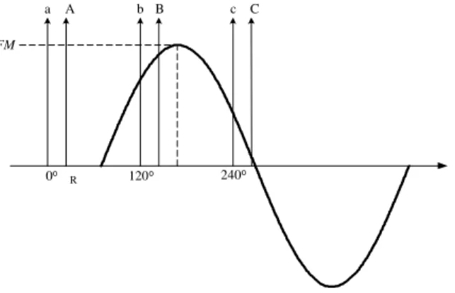
Suppose that the maximum value (FM) of this spatial
distribution is located at a position given by an angleα, at a certain instant of time, defined in aθreference axis
of which origin is coincident with the phase a winding
axis (figure 1). The distribution of magnetomotive force is written as
mmf(θ) =F Mcos(θ−α) =
n=a,b,c,A,B,C
2Knincos(θ−θn) (3)
where
F M - amplitude of the spatial distribution of
magneto-motive force;
θ - angular displacement along the reference axis;
Kn - winding factor of rotor and stator phases (a, b, c,
A,B,C);
θn - generic position of the rotor and stator phases
α- angular position of them.m.f peak.
a A b B c C
0o
R 120o 240o
FM
Figure 1: Spatial Distribution of the Magnetomotive Force.
Them.m.f(θ) produces a resultant distribution of
mag-netic flux density B(θ). Regarding the magnetizing
curve which characterizes the machine magnetic circuit,
the m.m.f (θ) distribution produces a non-sinusoidal
B(θ), but still symmetric in relation to the m.m.f (θ) axis.
The application of Fourier analysis leads to
B(θ) = h=1,3
Bhcos [h(θ−α)] (4)
where
Bh - maximum value of thehth component ofB(θ);
h- harmonic order.
Considering the winding of phase ndistributed in
sev-eral coils, each one withNturns, of which central axis is situated at aθnposition (figure 3), the total flux linking
Figure 2: Resultant spatial Distribution of Flux Density B(θ)
the winding due toB(θ) is
λmn=
h=1,3
FhF Mcos [h(α−θn)] (5)
whereFh
F M
is the “magnetic harmonic function”. It is obtained experimentally.
Figure 3: Distribution of (m.m.f(θ), Flux Density and Winding.
Manipulating (2), (3) and (5) as shown by Bispo et al. (2001), the following equations arise
fR(λ) =
n=a,b,c,A,B,C
λn
Ln
cos (θn) (6)
fI(λ) =
n=a,b,c,A,B,C
λn
Ln
sin (θn) (7)
f(λ) =
[fR(λ)] 2
+ [fI(λ)] 2
(8)
tg(α) = fI(λ)
fR(λ)
(9)
F1
F M
=f(λ)
AS
−F M
AS
(10)
AS = 3 2
1
Ls
+ 1
Lr
(11)
whereLs and Lr are the leakage inductances of stator
and rotor respectively. Equations (1) to (11) comprise the motor model.
The solution is as follows: from a numerical integration method, (1) is solved. For each integration step,Vn and
λn are known. From (6) – (8), f(λ) is calculated; As is determined in (11). Knowing the magnetic function
F1(F M), f(λ) and As, a line equation is defined by (10). The intersection of this line with the magnetizing
curve defines the values of F1(F M) and F M in each
integration step. The value ofF3
F M
The harmonic magnetic functions F1(F M) and
F3
F M
are determined experimentally driving the in-duction machine at synchronous speed. Different values of balanced and distortion-free three-fase voltage are ap-plied to the stator and the instantaneous values ofVnand
in are digitally stored. This current corresponds to ex-citation current. Taking the iron losses out of the mea-sured current and using the machine parameters, the in-stantaneous values of the magnetizing flux using (1) and (2) are determined. Fourier analysis providesF1(F M) andF3
F M
(figure 4), corresponding to the amplitude of its fundamental and third harmonic components.
Figure 4: Curves Experimentally Obtained: (a)
F1vs(F M) ; (b)F1vs(F M) .
3
SIMULATION RESULTS
Some simulations were performed in order to verify the behavior of the machine supplied by six step and sinu-soidal PWM converters. Analyses were carried for both star and delta winding connections, with the motor at no-load. Initially, the results are presented considering a linear magnetic circuit; in the sequence, the effects of the saturation and spatial 3rd harmonic of the air-gap flux are included. In the non-saturated condition, that is, considering the machine magnetic circuit linear, the air gap flux varies linearly with the magnetizing current (figure 2).
3.1
Six-step motor drive
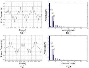
Figures 5 and 6 show results of simulation consider-ing linear magnetic circuit for the machine. Line and phase currents are shown for the delta connection under six-step driving in Figure 5. Figure 6 shows the phase voltage and line current for the six-step drive with ma-chine windings connected in star. The presentation of results along the paper is structured such as to show the corresponding frequency spectrum of the waveform un-der analysis. As expected from the analysis with linear magnetic circuit, only the harmonics originated by the switching strategy are present in the waveforms, which in the case of six-step drive correspond to 5th, 7th, 11th
(a)
Time(s) Harmonic order
(b)
(c) (d)
Time(s) Harmonic order
Amplitude(A)
Amplitude(A)
Line Current (A)
Phase Current (A)
3rd 5th
7th
3rd 5th
7th
Figure 5: Results for delta connection. (a) Line Cur-rent; (b) Frequency Spectrum; (c) Phase CurCur-rent; (d) Frequency Spectrum.
(a)
Time(s) Harmonic order
(b)
(c) (d)
Time(s) Harmonic order
Amplitude(A)
Amplitude(A)
Line Current (A)
Phase Current (A)
3rd 5th
7th 3rd
5th 7th
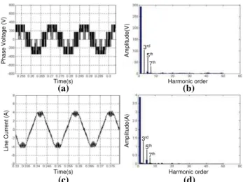
Figure 6: Results for star connection. (a) Phase Volt-age; (b) Frequency Spectrum; (c) Line Current; (d) Fre-quency Spectrum.
and 13th . . . harmonics.
Time(s) Harmonic order
(a) (b)
Amplitude(A)
Phase Current (A)
3rd 5th
7th 3rd
5th 7th
Figure 7: Results for delta connection. (a) Phase Cur-rent; (b) Frequency Spectrum.
Figure 8: Results for star connection. (a) Phase Voltage; (b) Frequency Spectrum.
Comparison of figures 8 and 6a-6b show the difference caused by the presence of third harmonic in this wave-form. It is important to observe that, as expected, the line currents for both star and delta connection do not show any distortion caused by the third harmonic com-ponent of air-gap flux either for delta or star connection.
3.2
Sinusoidal PWM motor drive
Simulations were also conducted with the machine be-ing fed by a sinusoidal PWM converter. As before, first the results for delta and star connections taken from lin-ear magnetic circuit modeling are shown, and in the se-quence those corresponding to saturated machine model are placed for comparison.
Figure 9 shows the line and phase current for delta con-nection and figure 10 shows the phase voltage and line current for star. As noticed, the PWM switching leads to improved waveforms, with negligible presence of low order harmonics.
With simulation including the effects of saturation, the phase currents for delta will show the distortions caused by the non-linearity of the magnetic circuit, which is confirmed by the corresponding frequency spectrum as seen in figure 11. For the star connection case, the dis-tortion is caused in the phase voltage as observed in figure 12.
(a)
Time(s) Harmonic order
(b)
(c) (d)
Time(s) Harmonic order
Amplitude(A)
Amplitude(A)
Line Current (A)
Phase Current (A)
3rd 5th
7th
3rd 5th
7th
Figure 9: Results for delta connection. (a) Line Cur-rent; (b) Frequency Spectrum; (c) Phase CurCur-rent; (d) Frequency Spectrum.
(a)
Time(s) Harmonic order
(b)
(c) (d)
Time(s) Harmonic order
Amplitude(A)
Amplitude(V)
Phase Voltage (V)
Line Current (A)
3rd 5th
7th
3rd 5th
7th
Figure 10: Results for star connection. (a) Phase Volt-age; (b) Frequency Spectrum; (c) Line Current; (d) Fre-quency Spectrum.
Time(s) Harmonic order
(a) (b)
Amplitude(A)
Phase Current (A)
3rd 5th
7th
Figure 12: Results for star connection. (a) Phase Volt-age; (b) Frequency Spectrum.
Figure 13: Rotor Current and Frequency Spectrum.
Rotor quantities, as well as the electromagnetic torque, will also be affected by the air-gap flux saturation. Figs. 13 and 14 show the simulated waveforms of the rotor cur-rent, its frequency spectrum and the steady-state elec-tromagnetic torque. The “flattened” air gap flux wave induces distorted voltage in the rotor, which in turn es-tablishes “flattened” rotor currents. Machine torque be-ing the result of interaction of air-gap flux and rotor current spatial distributions will be affected resulting in low frequency oscillations as shown in Fig. 14.
Another situation analyzed is the operation with voltage boost. A voltage 20% greater than the rated V/f value was supplied to the motor. This can occur in real cases when the stator voltage drop compensation for lower op-eration frequencies is excessive. In such situations, since the motor operates at a higher saturation level, the fun-damental component of the stator current is increased, as well as the presence of the spatial third harmonic. The results are observed in figure 15. Comparing ures 15a-15b, that correspond to linear model, with fig-ures 15c-15d, from the saturated model, one can note the higher value of fundamental component of current that occurs in the saturated condition (approximately
Figure 14: Eletromagnetic Torque.
(a)
Time(s) Harmonic order
(b)
(c) (d)
Time(s) Harmonic order
Amplitude(A)
Amplitude(A)
Phase Current (A)
Phase Current (A)
3rd 5th
7th 3rd
5th 7th
Figure 15: Phase current, delta connection. Operation with voltage boost - (a) Linear Model; (b) Frequency Spectrum; (c) Non-linear Model; (d) Frequency Spec-trum.
20% higher). This indicates a considerable error when using a linear model for this operation condition. Fur-thermore, the increased saturation leads to a stronger flattening in the flux distribution, which is reflected in higher third harmonic component in the phase current, as noticed in figure 15. Comparing with figure 11a, a threefold increase in the magnitude of the third har-monic is observed.
4
EXPERIMENTAL RESULTS
1) Line Current (A): 3 Volt 10 ms
1) Phase Current: 2 Volt 10 ms
(a)
Time(s) Harmonic order
(b)
(c) (d)
Time(s) Harmonic order
Amplitude(A)
Amplitude(A)
Line Current (A)
Phase Current (A)
3rd 5th
7th
3rd 5th
7th
Figure 16: Results for delta connection. (a) Line Cur-rent; (b) Frequency Spectrum; (c) Phase CurCur-rent; (d) Frequency Spectrum.
1) Phase Voltage (V): 50 Volt 10 ms
1) Line Current (A): 2 Volt 10 ms
(a)
Time(s) Harmonic order
(b)
(c) (d)
Time(s) Harmonic order
Amplitude(A)
Amplitude(V)
Phase Voltage (V)
Line Current (A)
3rd 5th
7th
3rd 5th
7th
Figure 17: Results for star connection. (a) Phase Volt-age; (b) Frequency Spectrum; (c) Line Current; (d) Fre-quency Spectrum.
motor is driven at no-load. A six-step converter with IGBT module was built in the laboratory for experi-ments. PWM modulation driving was realized with a commercial converter.
4.1
Six-step motor drive
Figure 16 presents the voltage and six-stepped line and phase currents waveforms for the delta-connected motor. It is observed that the results are in very good agreement with those originated by simulation. As expected, the
1) Line Current (A): 2 Volt 5 ms
1) Phase Current (A): 1 Volt 5 ms
(a)
Time(s) Harmonic order
(b)
(c) (d)
Time(s) Harmonic order
Amplitude(A)
Amplitude(A)
Line Current (A)
Phase Current (A)
3rd 5th
7th 3rd
5th 7th
Figure 18: Results for delta connection. (a) Line Cur-rent; (b) Frequency Spectrum; (c) Phase CurCur-rent; (d) Frequency Spectrum.
third harmonic is present in the phase current, as con-firmed by the frequency spectrum. Phase voltage and line current from star-connected operation are shown in figure 17. The “rounded” shape indicated by the simula-tion is confirmed in this measurement, and the amount of third harmonic present due to saturation is indicated in the waveform frequency spectrum.
Phase voltage and line current from star-connected op-eration are shown in figure 17. The “rounded” shape indicated by the simulation is confirmed in this measure-ment, and the amount of third harmonic present due to saturation is indicated in the waveform frequency spec-trum.
4.2
Sinusoidal PWM motor drive
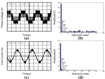
Measurements with a 4 kHz sinusoidal PWM commer-cially available converter were also taken as shown in figure 18. There is a clear presence of the harmonics in the phase current due to saturation for the delta con-nection (figures 18c-18d). As observed in the simulation, the line current is free from the saturation harmonic.
Distorted phase voltage is observed in the measurement shown in figure 19 for the star connected motor, con-firming the predicted by simulation.
1)Phase Voltage (V): 200 Volt 5 ms
1) Line Current (A): 1 Volt 5 ms
(a)
Time(s) Harmonic order
(b)
(c) (d)
Time(s) Harmonic order
Amplitude(A)
Amplitude(V)
Phase Voltage (V)
Line Current (A)
3rd 5th
7th
3rd 5th
7th
Figure 19: Results for star connection. (a) Phase Volt-age; (b) Frequency Spectrum; (c) Line Current; (d) Fre-quency Spectrum.
1) Phase Current (A): 2 Volt 5 ms
Time(s) Harmonic order
(a) (b)
Amplitude(A)
Phase Current (A)
3rd 5th
7th
Figure 20: Operation with voltage boost. (a) Phase Current (delta connection); (b) Frequency Spectrum.
5
CONCLUSIONS
This work has presented a theoretical-experimental an-alyzis of the induction motor behavior fed by static con-verters considering the magnetic circuit saturation. Six-step and sinusoidal PWM modulation techniques were studied and implemented for both delta and star wind-ing connections. The comparison between the exper-imental and simulated results obtained with the
non-linear model shows very good agreement. Analyzes
based on linear magnetic circuit are inherently inaccu-rate, since the harmonic components are not accounted for neither in the stator and rotor quantities nor in the electromagnetic torque. It was observed that the ef-fects of the air gap flux harmonics are manifested in the phase currents for the delta-connected machine, while the phase voltages are affected when the machine is star-connected. In addition, saturation effects are also ob-served in rotor quantities and electromagnetic torque, as third-order harmonics in rotor currents and
oscilla-tions in the motor torque.
REFERENCES
Bispo, D., et al., (2001). A New Strategy for Induction Machines Modeling Taking into Account the
Mag-netic Saturation. IEEE Transactions on Industry
Applications. Vol. 37, N0
. 6, pp. 1710–1719.
Khater, F. M., et al. (1987). Selection of Flux Level in Field-Oriented Induction Machine Controllers with
Consideration of Magnetic Saturation effects.IEEE
Transactions on Industry Applications. Vol. IA-23,
N0
. 2, pp. 276 – 282.
Levi, E. (1994). Applications of the current state space model in analyses of saturated induction machines.
Electric Power Systems Research. Vol. 31, N0
. 3, pp. 203-216.
Levi, E. (1996a). Main Flux-Saturation Modelling in d-q Axis Models of Induction Machines Using Mixed
Current-Flux State-Space Models. ETEP. Vol. 6,
N0. 3, pp. 207–215.
Levi, E. (1996b). Main Flux Saturation Modelling in Double-Cage and Deep-bar Induction Machines.
IEEE Transactions on Energy Conversion. Vol. 11,
N0
2, pp. 305–311.
Liao, Y., et al. (1994). Effect of Saturation Third Har-monic on the Performance of Squirrel-Cage
Induc-tion Machines.Electric Machines and Power
Sys-tems. Vol. 22, pp. 155-171.
Melkebeek, J. A. A., et al. (1983). The Influence of Saturation on Induction Machine Drive Dynamics.
IEEE Transactions on Industry Applications. Vol.
IA-19, N0
5, pp. 671-681.
Moreira, J. C., et al. (1992). Modelling of Saturated ac Machines Including Air Gap Flux Harmonic Com-ponents. IEEE Transactions on Industry Applica-tions. Vol. 28, N0
2, pp. 343–349.
Neto, L. M., et al. (1999). Analysis of a Three-Phase Induction Machine Including Time and Space Har-monics Effects: The A, B, C Reference Frame.
IEEE Transactions on Energy Conversion. Vol. 14,
N0
1, pp. 80–85.
Neto. L. M., et al. (1999). Magnetic Saturation
Ef-fect on a Three-Phase Induction Machines. IEEE
Ojo, O., et al. (1994). Steady-State Performance Evalua-tion of Saturated Field Oriented InducEvalua-tion Motors.
IEEE Transactions on Industry Applications, Vol.
IA-30, N0
6, pp. 1638–1647.
Resende, J. T. (1999). Modelagem da M´aquina de
In-du¸c˜ao Trif´asica, incluindo a Satura¸c˜ao Magn´etica – An´alise Dinˆamica do Gerador de Indu¸c˜ao
Auto-Excitado. Tese de Doutoramento, UFU, Uberlˆ
an-dia.
APPENDIX I - MOTOR PARAMETERS
Table 1: Induction Motor Data.
Output rated power 1.5 kW
Rated speed 1720 r/min
Line voltage (∆/Υ) 220/380 Volts rms
Stator resistance 3,11 Ω
Rotor resistance 3,83 Ω
Stator leakage inductance 8,4 mH
Stator leakage inductance 8,4 mH
Magnetization inductance 127 mH