A New Multi-Band Multiple Beam Forming
Nolen Matrix Antenna Feeding Network for
Cognitive Radio
Sivasundarapandian.S#1, C.D.Suriyakala*2
#
Sathyabama University, Chennai, India
1
*
Sree Narayana Gurukulam College Of Engineering. Kerala, India
2
Abstract— A novel method of Beam forming network for multiband frequencies based on Nolen matrix (4×4) topology using multiband 90º ring Coupler was proposed and its performance was analyzed in this paper. The above method is able to produce a multiband Beam forming output with different center resonant frequencies for 2.8GHz, 6.3GHz and 9GHz which provides beam steering in various directions so as to avoid the interference between the users. Beam steering is used in smart antenna to minimize the wastage of power and to maximize the directivity in the desired direction .This formation was simulated and measured using Microstrip technology in ADS (Advanced Design system) software . The simulated and measured results show the good agreement in return loss.
Keyword- ring coupler; multiband Beamforming network; nolen matrix
I. INTRODUCTION
In wireless communication industry spectrum scarcity is a foremost problem. There is no liberally accessible spectrum for the prospect age group. No more than ten percentage of occasion the spectrums is exploited capably and respite of the occasion it is seem to be unused. Cognitive Radio successfully administers the Spectrum by jerky the frequency bands with moment and convenience to become responsive of that which channel is in use. By means of Cognitive Radio secondary clients can exploit the spectrum exclusive of interfering with the primary users. In cognitive radio base station the radiation pattern of the antenna should be omnidirectional in an attempt to sense the spectrum in every part of the directions and in transmitter the radiation pattern should be unidirectional to avoid the interference, wastage of power radiated in unwanted direction and to increase the radiated power in the preferred direction. The beam forming matrix can be exercised as a feeding network for the antenna array. There are different types of beam forming networks like Butler matrix, Blass matrix and Nolen matrix. The present progress in wireless communication industry shows that the multiband compact dimension couplers are used in an assortment of applications. A novel method of Beamforming networks for multiband frequencies based on Nolen matrix (4×4) topology was projected in this paper. It is able to produce a multiband Beamforming output with different centre frequencies. This structure is simulated in ADS (Advanced System Design) software. It has the advantages like resonating at different frequencies ,reducing the use of different structures for various frequencies, compact size, low cost, less weight and it can be easily fabricated .The fundamental building block for Nolen matrix used in this design is a multiband ring coupler. This multiband ring coupler consists of two concentric rings as shown in figure 1.The outer ring is designed for low frequency of operation and the inner ring is responsible of higher band of frequencies of operation.
implemented [4] with different coupling factors and phase shifters. A Nolen matrix was simulated and measured from Blass matrix design algorithm with the amplitude and phase output excitation laws of a Butler matrix using 90 hybrid ring couplers [5]. In [6] a reduced- size cascaded Butler matrices with dual-band and dual-beam (narrow and broad) was generated using modified branch line coupler. A [7] dual-band inset-fed reconfigurable antenna is designed with reconfigurability and adaptivity in a single array. Also a RF MEMS switch is used in this design to change the frequency of operation. In [8] a nolen matrix was designed with modified couplers and phase shifters by forming the sub networks. Also in the output circuit Wilkinson power combiner is used to combine the output of sub networks. A 4×8 Nolen matrix using micro strip technology is implemented in [9] to reduce the side lobe level in linear arrays and the result was compared with butler matrix and proved that it is compact. In [10] [11] A nolen matrix based on SIW technology for Ku band was analyzed. A dual band ring coupler was designed in [12-15]. The 12-open stubs on inside of the ring coupler are designed for reducing the size without any lumped components [16].
Section II describes the ring coupler as the basic design for implementing the Nolen matrix with Single band and Triband Ring coupler. Section III shows the detailed explanation of MIMO Matrix such as Nolen matrix and its layout for Triband of Operation is shown. Section IV shows the simulated results and Radiation pattern of Triband Nolen Matrix. Section V shows Conclusions and followed by References.
II. PROPOSED RING COUPLER STRUCTURE
For designing Ring coupler, specification such as coupling, isolation and matching should be considered. Ring coupler is the basic design for developing the Nolen matrix. Coupler has 4 ports and 4th port is isolated port. Ring coupler is designed with one-quarter wavelength section and 90º angle of Mcurve with width W=1.5mm.The Length and Width of the transmission line is L=15mm and W=2.86mm.This structure is implemented in FR4 material with thickness of 1.6mm and permittivity is 4.5 and loss tangent 0.02 conductor thickness is 1um. Fig.1. shows the single band ring coupler.
Fig. 1.Layout of Single band Ring coupler
The layout of single band ring coupler simulated in ADS is shown in figure.1. and the return loss is shown in figure 2. Multiband Ring coupler was designed with addition of 8-short circuited stubs to single band Ring coupler. The Stub is transmission line length and it can be either short circuited or open circuited. It is one of the distributed circuit elements. Fig.3 shows the Multi-band Ring Coupler. The input impedance of short circuited stub (MLSC) is
Where ‘Zin’ is input impedance and ‘ l’ is the length of the stub
Fig. 2. Simulated result of Return loss for single-band Ring Coupler
For Beam forming network different MIMO Matrices has been used such as BUTLER Matrix, Nolen Matrix. Beam forming is processing of RF Signal by sending out the multiple signals from radiating elements and analyzing the best path. Butler Matrix is built by
Fig. 3. Layout of Multi band Ring Coupler
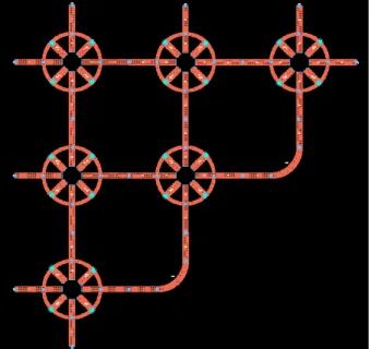
interconnecting Hybrid Coupler, phase shifters and crossover. Hybrid coupler has 4 ports with each separated by ¼ wavelength occupied at half ring, other half has ¾ wavelength. A 4×4 Butler Matrix has 4 inputs and 4 outputs, the RF signal fed to 4 inputs and different beams are produced. The User can select the direction of beam radiation by feeding any of the input port. The multiband Nolen matrix was designed on the same substrate and same dimension as considered in single band ring coupler in addition of 8-stubs with width W=2.86mm and length L=10mm. FR4(Flame Resistance Board) is low cost substrate which is used for integrating the Butler matrix and antenna elements during PCB fabrication process. For more advantages, we designed a 4×4 Nolen matrix which working in Multiband of Frequency. The 8-Stubs have been added with the each ring coupler of single band Nolen matrix. The multiband operation has been done and only less number of hardware is required. Figure.5 shows the proposed 4×4 Multiband Nolen matrix. The RF signal is given to 4 input ports and 4 output ports have been connected with the antenna array elements. The different inputs ports have been excited for various beam direction. The user may choose the particular direction with enabling the certain port and maintaining the other ports without excitation. Microstrip transmission line is preferred planar transmission line for the realization of planar circuits.
The User can select the direction of beam radiation by feeding any of the input port. The multiband Nolen matrix was designed on the same substrate and same dimension as considered in single band ring coupler in addition of 8-stubs with width W=2.86mm and length L=10mm. FR4(Flame Resistance Board) is low cost substrate which is used for integrating the Butler matrix
2 4 6 8
0 10
-25 -20 -15 -10
-30 -5
Frequency[GHz]
M
a
g
. [d
B]
Fig.4. Dimensions of proposed Multi band Ring Coupler
and antenna elements during PCB fabrication process. For more advantages, we designed a 4×4 Nolen matrix which working in Multiband of Frequency. The 8-Stubs have been added with the each ring coupler of single band Nolen matrix. The multiband operation has been done and only less number of hardware is required. Figure.5 shows the proposed 4×4 Multiband Nolen matrix. The RF signal is given to 4 input ports and 4 output ports have been connected with the antenna array elements. The different inputs ports have been excited for various beam direction. The user may choose the particular direction with enabling the certain port and maintaining the other ports without excitation. Microstrip transmission line is preferred planar transmission line for the realization of planar circuits. Stubs are responsible for single frequency of operation while the inner stubs are responsible for multiband frequency operation
TABLE I
Beam radiation (phase in degree) for the various ports excitation at different frequencies.
Frequency (GHz)
Port 1 (deg)
Port2 (deg)
Port3 (deg)
Port4 (deg)
2.8 0 0 90 0 6.4 210 210 240 300
9 0 90 0 90
TABLE II
Values of return loss for simulated and measured results at different frequencies
Frequency (GHz)
Simulated (deg)
Measured (deg)
2.8 -23 -20 6.4 -15 -20 9 -17 -24
TABLE III
Phase difference of output ports at different frequencies
Frequency (GHz)
Port 6&5 (deg)
Port7&6 (deg)
Port8&7 (deg)
2.8 -112 -143 -37 6.4 95 123 78
III.SIMULATION RESULTS AND DISCUSSION
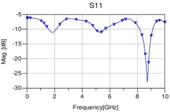
For a designed 4×4 Nolen matrix, the multiband frequency has been obtained with the ADS momentum simulator. Figure.6 shows the result of Return loss for the modified Ring Coupler design. The multiband frequency has been obtained for this coupler at 2.8GHz, 6.4GHz, and 9GHz.After that nolen matrix was constructed by using six multiband ring couplers as shown in figure 5. The simulated result of Return loss for multiband 4×4 Nolen matrix is shown in figure 7. Radiation pattern is visualization pattern which shows angle of direction of radiated beam at different planes. In momentum simulator, post processing step is used to generate the radiation pattern. Radiation pattern is calculated for different frequency as shown in table. Amplitude was selected as 1Volts for each port excitation. Fig.10. shows the radiation pattern of 2.8GHz frequency with each port excitation. This figure Shows the maximum beam radiation at different angle with four input ports excitation. Such that each port shows maximum beam radiation at different direction as shown in Fig.11 and Fig.12. The maximum beam radiation for the various ports excitation at different frequency was shown in the table1. Less hardware is required in view of the fact that working in multiband of frequencies. As there is no crossover, size of the design is reduced. Power Consumption is low since transmission is towards the particular direction. The maximum beam radiation for the various ports excitation at different frequency was shown in the table1. The simulated and measured results were compared in table2.
Fig. 7. Simulated result of Return loss for Multi-band Ring Coupler
Fig. 8. Simulated result of Return loss for multiband 4×4 Nolen matrix.
Fig. 9. Measured result of Return loss for multiband 4×4 Nolen matrix.
2 4 6 8
a) b)
c) d)
Fig.10.E- field Radiation Pattern at 2.8GHz a) Port1 b) port2 c) port3 d) port4
a)
b)
c) d)
a) b)
c)
d)
Fig.12.E- field Radiation Pattern at 9 GHz a) Port1 b) port2 c) port3 d) port4
IV.CONCLUSION
The results of a compact and modified multiband 4×4 Nolen matrix were presented in this paper with the previous consideration such as Single band Nolen matrix design. In our proposed work multiband frequency has been obtained at 2.8GHz, 6.4GHz, and 9GHz as the simulation result of new design Nolen Matrix by adding eight short circuited stubs. The radiation pattern for different frequencies with various port excitation was tabulated which shows the beam forming in different directions. In the output of nolen matrix multiband antennas or multiband antenna at four ports could be connected for beam steering. The user may choose the particular direction with enabling the certain port. Thus the performance of beam forming network was analyzed using multiband Nolen matrices which show that it has good performance for all the three resonant frequencies.
REFERENCES
[1] N.J.G.Fonseca, “Printed S-band 4×4 Nolen matrix for Multiband Antenna application,”IEEE trans. Antenna and Propagation, vol.57, no.6, pp.1673-1678, 2009.
[2] Tarek Djerafi, Hervé Aubert, “Ridge Substrate Integrated Waveguide (RSIW)Dual-Band Hybrid Ring Coupler”, IEEE microwave and wireless components letters, vol. 22, no. 2, february 2012
[3] Tarek Djerafi, Nelson J. G. Fonseca, “Broadband Substrate Integrated Waveguide 4× 4 Nolen Matrix Based on Coupler Delay Compensation”, IEEE transactions on microwave theory and techniques, vol. 59, no. 7, july 2011
[4] Tarek Djerafi, Nelson J. G. Fonseca, “Planar Ku-Band 4 4 Nolen Matrix in SIW Technology”,IEEE transactions on microwave theory and techniques, vol. 58, no. 2, february 2010.
[5] Nelson J. G. Fonseca, “Printed S-Band 4 4 Nolen Matrix for Multiple Beam Antenna Applications”, IEEE transactions on antennas and propagation, vol. 57, no. 6, june 2009,pp.1673-1678.
[6] Noorlindawaty MD. JIZAT, Sharul Kamal ABD. Rahim, Muhammad Zairil M. NOR,Yusoff Abdulrahman, Mursyidul Idzam sabran, Mohd. Faizal JAMLOS “Beamforming Network Using Dual Band-Dual BeamReduced Size Butler Matrices”, radioengineering, vol. 22, no. 3, september 2013,pp.769-775.
[7] Hamid Torpi , Yasin Damgac, “Design of Dual-band Reconfigurable Smart Antenna”, Progress In Electromagnetics .Research Symposium 2007, Prague, Czech Republic, August 27-30,pp.425-429.
[8] Fanourios E. Fakoukakis and George A. Kyriacou, “ Novel nolen matrix based beamforming networks for series-fed low sll multibeam antennas”, Progress In Electromagnetics Research B, Vol. 51, 2013,pp.33-64.
[9] N.J.G.Fonseca, N. Ferrando, “Nolen matrix with tapered amplitude law for linear arrays with reduced side lobe level,”in Proc. EuCAP, Barcelona, Spain,2010,pp.1–5.
[10] A.Ali, F.Coccetti,H. Aubert,N.J.G. Fonseca, “ Novel multi-layer SIW broadband coupler for Nolen matrix design in Ku band”, AP-S IEEE,2008,pp.1-4.
[11] T.Djerafi,Ecole Polytech. de Montreal,QC. Montreal,N.J.G. Fonseca, Ke Wu,“Architecture and implementation of planar 4 ×4 Ku-Band Nolen Matrix using SIW technology”,APMC,Macau,2008,pp.1-4.
[12] Yi-Chyun Chiou ; Jen-Tsai Kuo ; Chi-Hung Chan , “ New miniaturized dual-band rat-race coupler with microwave C-sections”, IEEE MTT-S,2009,pp.701-704
[13] Ching-Luh Hsu , Chin-Wei Chang , Jen-Tsai Kuo , “Design of Dual-Band Microstrip Rat Race Coupler with Circuit Miniaturization”, Microwave Symposium, Honolulu 2007,pp.177-180.
[14] Jun Xing , Mingqiang Bai , Pengcheng Li , Deqiang Yang, “The new design of miniaturized dual-band 180° hybrid-ring coupler”,iWEM,IEEE, Chengdu, Sichuan,2012,pp.1-3.
[16] M.L.Chuang. Miniaturized Ring Coupler of Arbitrary Reduced size, IEEE Microwave and wireless components letters, vol. 15, Nº 1, 16-18 (2005).
[17] http://en.wikipedia.org/wiki/Beamforming.
AUTHORPROFILE
Sivasundarapandian.S was born in Athipatti, Madurai,Tamilnadu, India.He received the B.E. degree in electronics and communication engineering from Madurai Kamaraj University,India, and M.Tech in VLSI Design from Sathyabama University ,Chennai, India. .Since 2008, he has been with Department of Electronics and Telecommunication Engineering, Sathyabama University, Chennai, India. Since 2011, he has been working toward the Ph.D. degree in the same University. His research interests include Microwave Devices , multi-band Antennas and RF circuit design