Abstract— The design of a compact microstrip line-fed Ultra- wideband (UWB) monopole antenna with a notched band characteristic is presented in this paper. The rejection frequency band occurs around 5-6 GHz, which is appropriate for wireless local area network (WLAN) applications and is obtained by a split-ring resonator on the antenna ground plane. The proposed antenna is printed on FR4 substrate material with a dielectric constant of 4.4. The dimension of the proposed antenna is 24×16×0.8 mm3. Radiating patch has a combined geometry realized by a half-circular ring and half-square ring. To achieve a proper impedance matching and increased bandwidth with VSWR ≤ 2, the study made use of an L-shaped element which was connected to the ground plane; moreover, the researchers added a split-ring resonator onto the ground plane to obtain one notched band. The comparison of the proposed antenna performance with previously presented UWB monopole antennas, was performed by using Analytic Hierarchy Process method. A good agreement was observed between simulated and experimental results.
Index Terms— Monopole antenna, Ultra-wideband, split-ring resonator, Analytic Hierarchy Process, WLAN band.
I. INTRODUCTION
Ultra-wideband (UWB) technology has attracted increasing interest due to its potential applications
in wireless communication systems. The Federal Communications Commission (FCC) selected the
frequency band of 3.1–10.6 GHz as the appropriate frequency band for commercial UWB systems
[1]-[2].
The development of ultra-wideband antennas assisting high data transmission rates, low power
consumption, and simple configuration guaranties a high-performance communication system.
Antennas capable of operating in UWB communication systems must have small size, wider
bandwidth, easy fabrication, and omnidirectional radiation pattern over the operation frequency band
[2]-[4]. A monopole antenna with microstrip fed line consists of a radiation patch of any planar
A Compact UWB Monopole Antenna with
Rejected WLAN Band using Split-Ring
Resonator and Assessed by Analytic Hierarchy
Process Method
S. R. Ebadzadeh, Y. Zehforoosh
Department of Electrical Engineering, Urmia Branch, Islamic Azad University, Urmia, Iran, [email protected] , [email protected]
M. Mohammadifar, M. Zavvari, P. Mohammady
such as E-shaped, C-shaped, arc shaped, and U-shaped slots on the radiation patch or ground plane
which result in rejecting the band frequency [5]-[10]. Bastani et al. proposed using omnidirectional
UWB monopole antenna with WLAN notched-band functionality. They showed that the use of the
width and the position of the C-shaped slots in the ground plane makes it possible to obtain the
optimized configuration of the slots, and reject WLAN band. Yadav Ajay et al. proposed using L and
U Slot Loaded UWB Microstrip Antennas (i.e., C-band/WLAN notched antennas). They showed that
by using the antennas loaded by L and U slots, it is possible to create dual band-notched
characteristics for WLAN and C-band satellite communication systems, respectively. Matin proposed
using a new design and analysis for microstrip-fed ultra-wideband printed monopole antenna. He
showed that by the inclusion of U-shaped slot on to the patch, a frequency notched characteristic is
achieved which can reject the frequency band of WLAN [3]. Jangid et al. proposed using circular
patch antenna with defected ground for UWB communication with WLAN band rejection. They
showed that by using L shaped slots in the ground plane and U shaped slot in the patch, the WLAN
band rejection is possible.
In this paper, a compact UWB monopole antenna with one notched band at the wireless local area
network, and (5-6 GHz) frequency bands, is studied. Some different techniques were used for better
frequency band rejection and the results were compared with previous works. Since there is a
trade-off between different performance metrics of various designs of antennas, one needs to make decision
for choosing the best efficient antenna. The comparisons were performed using Analytic Hierarchy
Process (AHP) method and the results confirmed the high-performance operation of the proposed
antenna.
II. DESIGN AND PARAMETRIC ANALYSIS OF ANTENNA
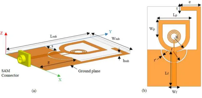
The geometry of the proposed compact Ultra-wideband (UWB) monopole antenna is shown in
Fig. 1. The front geometry of the antenna is a half-circle that plays the role of a radiation element.
Moreover, this antenna uses a modified ground plane at the bottom surface for increasing the
bandwidth. The conductive parts of the antenna are printed on the FR4 substrate with a thickness of
0.8 mm, dielectric constant of 4.4, and loss tangent of 0.02. The total size of the proposed antenna is
16×24×0.8 mm3 in x, y, and z directions, respectively. The design of the feed line of the antenna helps
Fig. 1. The structure of the proposed antenna a) front view, b) side view.
TABLE I. THE OPTIMIZED VALUES OF THE PROPOSED ANTENNA PARAMETERS.
Parameters Value (mm) Parameters Value (mm)
L sub 24 W sub 16
h sub 0.8 Wp 4.7
Lp 9.4 s 4
t 1.2 R 4.2
R´ 4.7 e 6
a 1.8 b 1.6
r 3.7 r´ 0.3
g 11 Wf 1.4
Lf 11.5
Here, a brief explanation is presented on split-ring resonator illustrated in Figure 2. This resonator
has a circuit including the inductor and capacitance. The inductance of ring is represented by L and
the distributed capacitance is represented by C1/2, C2/2, and C3/2 where C1/2 is the capacitance
composed by the upper outer and inner ring, C2/2 is the capacitance composed by lower outer and
inner ring, and C3/2 is the capacitance composed by the lowest outer and inner ring. It should be
mentioned that all the three capacitances are connected in series. SRR structure is designed from
microstrip substrate parts, since the shape, direction, and SRR structure adjustment are important in
changing the inductor and capacitor [12]-[15].
In order to have a frequency band rejection, the researchers created a split-ring resonator element,
or simply a resonator, and connected it to a part of the ground plane with a curve. As shown in Figure
2, in this split-ring resonator, (a) is the radius of the outer circle and (b) is the radius of the inner
circle. An increase or decrease in the radius of the rings has a significant effect on the displacement of
In the following, the development stages of the proposed antenna design and the effect of the
changes of the values of (e) and (r´) parameters on the bandwidth and band notch performance in the
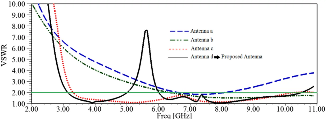
antenna are presented and discussed. Fig. 3 shows the development of the proposed UWB antenna.
The antenna is patched; it consists of a half-circular ring and a half-square ring. In addition, it has a
rectangular partial ground plane (Fig. 3(a)) with an unsuitable bandwidth and VSWR ≤ 2. Since the
current mostly passes through the edges, the result is a mixture geometry composed of a half-circular
ring with an inner radius R, an outer radius R´, a half-square ring of side Lp and width Wp = Lp/2, as
appeared in Fig. 3(b). This antenna shows impedance conformity in the wide frequency range of
VSWR ≤ 2. By adding a curve on the ground plane under the patch, the impedance performance is
improved. The curve radius conforms the outer radius of the patch above it. This curve increases the
total bandwidth, over which the back current passes; this ultimately leads to an increase in the
inductive effect. In addition, a narrow half-circle split with radius (r) and outer radius (r + r´) is
created on the ground plane. The inductive effect increases with the creation of the split, which
decreases the Q factor resulting in a further increase in impedance bandwidth. In order to observe the
characteristics of UWB, the researchers added a ground stub of length, L´ = L –g + e and width (t) to
the ground plane as in Fig. 3(c). Moreover, the study took the optimal length of 11 mm for the ground
plane to preserve a proper impedance conformity and multi-directional pattern over the entire UWB.
The antenna showed a UWB of 7.8 GHz, which covered 3.1-10.7 GHz with VSWR ≤ 2 Fig. 3(c). Fig.
3(d) shows the proposed antenna. It is a circular split ring resonator (SRR). Fig. 4 shows the VSWR
III. THERESULTSOFSIMULATIONANDMEASUREMENT
To achieve a suitable impedance matching with VSWR ≤ 2 and to obtain one notched band
characteristic, the researchers connected an L-shaped element to the ground andadded a SRR onto the
ground plane, respectively, as shown in Fig. 3. This frequency band rejection occurs due to a
split-ring resonator which leads to the changes in the plane direction and creation of the notch on that
frequency band. The simulated VSWR characteristics of the various antenna structures are shown in
the Fig. 4. In Fig. 5, Voltage Standing Wave Ratio (VSWR) characteristics for various values of (e)
are shown. This diagram indicates that by reducing parameter (e) in the antenna shape, bandwidth
reduces, and by changing the bandwidth WLAN is removed. Therefore, the value of this parameter (e
= 6 mm) is important in avoiding the reduction in bandwidth and rejection of WLAN.
Fig. 4. Simulated VSWR characteristics of the various antenna structures shown in Fig. 3.
Fig. 5. VSWR characteristic for different values of the e.
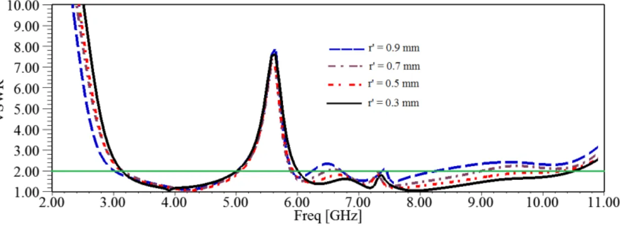
VSWR characteristics of the proposed antenna with various (r´) are shown in Fig. 6. This figure
demonstrates that by increasing parameter (r´), antenna bandwidth reduces. Therefore, the value of
Fig. 6. VSWR characteristic for different values of the r´
The bandwidth frequency can be controlled for different values of (e) and (r´). Fig. 7 shows a
prototype of the proposed antenna, which is fabricated on FR4 substrate. All the simulated results are
obtained by HFSS software. The radiation patterns of the antenna for 4, 8, and 10 GHZ are shown in
Fig. 8. The antenna is omnidirectional at low frequencies and near-omnidirectional at high
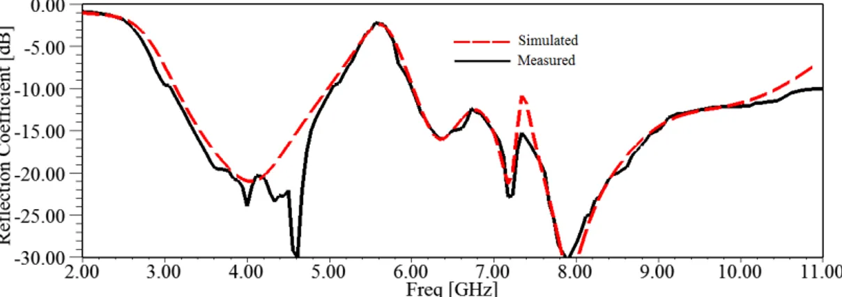
frequencies. The simulated and measured reflection coefficient (S11) of the proposed antenna are
shown in Fig. 9. The measured bandwidth is improved from 3.1 to 10.6 GHz.
Fig. 9. Simulated and measured reflection coefficient of the proposed antenna.
A. The comparisons using the Analytic Hierarchy Process method
Analytical Hierarchy Process (AHP) is one of the most popular versatile decision making
techniques developed by Thomas. L. Saaty in the 1970s [16]. This technique is one of the most
comprehensive techniques of Multiple Attribute Decision Making (MADM). It (AHP) can be used
when decision making process is faced with several options with similar criteria. The proposed
criteria could be qualitative and quantitative. This method is based on pairwise comparisons. The
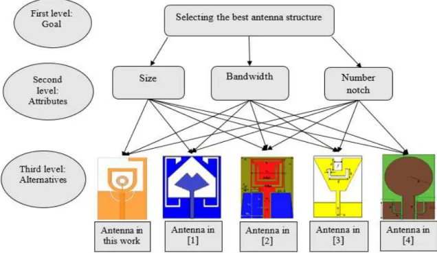
decision maker starts by providing a decision tree. The decision tree includes goal, attributes, and
alternatives. The goal is selecting the best antenna structure. The most important attributes are size,
bandwidth, and the number of notches. Alternatives are the other previously designed antennas
compared with the proposed one in this study. Then a series of pairwise comparisons are performed.
Finally, AHP combines the matrices resulted from pairwise comparisons so as to achieve the optimal
decision.
The comparison between the proposed antenna in this work and other antennas presented in [1]-[4]
is shown in Table II. Analytical Hierarchy Process is basically one of the Multi Attribute Decision
Making techniques. The goal of the AHP is to assist in selecting and judgment for making more
effective decisions. The AHP includes three levels of goal, attributes, and alternatives in this paper.
The AHP schematic of the antenna proposed in this work and those of other antennas are shown in
Fig. 10.
TABLE II. THE COMPARISON BETWEEN THE PROPOSED ANTENNA IN THIS WORK AND OTHER ANTENNAS.
Reference Bandwidth (GHZ) %
Notch band Frequency
(GHZ)
Size (mm3) Number notch
ℰr
This work 125% 5-6 307.2 1 4.4
[1] 135.2% 5-6 1440 1 2.2
[2] 114.2% 3.8-4.2 & 5.1-5.8 1248 2 4.4
[3] 124% 5.15- 5.825 1075.2 1 4.4
Fig. 10. Analytic hierarchy process schematic of the antenna proposed in this work and other antennas.
In order to apply the AHP method, the researchers defined a utility function for selecting an antenna
which is based on Simple Additive Weighted (SAW) method shown in Equation (1).
U Antenna (j) = W size× U size (Antenna (j)) + W Bandwidth× U Bandwidth (Antenna (j)) +W Notch × U Notch (Antenna (j)) (1)
In Equation (1), a profit value is assigned to each of the attributes (i.e., Usize, UBandwidth and
UNotch) when selecting the alternatives. Wsize, WBandwidth and WNotch are the weights given to size,
bandwidth, and number of notches, respectively. Table III shows the importance of the cases. In case
1, size, bandwidth, and number of notches have equal weight values (i.e., none of them is more
important than the others). In case 2, ‘size’ has the highest weight value. In case 3, ‘bandwidth’ has the highest weight value. In case 4, ‘the number of notches’ has the highest weight value. It should be mentioned that in each of the cases, the sum of the values is equal to one.
TABLEIII.DISCUSSED CASES FOR WEIGHT ASSIGNMENTS TO DIFFERENT VALUES.
Cases Wsize WBandwidth WNotch
Case1 0.33 0.33 0.33
Case2 0.5 0.25 0.25
Case3 0.25 0.5 0.25
Case4 0.25 0.25 0.5
Cases Antenna in this work
Antenna in [1]
Antenna in [2]
Antenna in [3]
Antenna in [4]
Case1 0.248 0.171 0.223 0.177 0.181
Case2 0.289 0.161 0.204 0.170 0.176
Case3 0.233 0.185 0.213 0.184 0.185
Case4 0.230 0.171 0.247 0.175 0.177
Nowadays, in line with the development of AHP, some software are developed based on its theory
that has made matrix solving processes and priority calculations incredibly simple. One of these
software is Expert choice software [17], [18].
To calculate the relative values, one should first solve complex matrices which can be solved easily
using Expert choice software. The data obtained from these calculations are presented in Table IV.
According to the data obtained from Table IV, a bar graph is drawn which is illustrated in Fig. 11.
Since the proposed antenna has a smaller size compared to antennas presented in references [1]-[4], it
indicated higher weight values in cases 1, 2, and 3. However, with regard to case 4, it has a lower
value compared to reference [3]; this is because reference [3] has 2 notches, whereas the proposed
antenna in this study possesses 1 notch. In fact, it is a reasonable comparison of the proposed antenna
with other previously designed antennas.
This diagram suggests that the priority of each antenna is determined based on various criteria used
for analyzing the data to choose the most appropriate antenna considering all the features. Based on
the above discussion, the proposed method is an appropriate tool for making decisions in terms of
choosing the best antenna structure.
Hierarchy Process (AHP) method using Expert Choice software. The results confirmed the priority of
the structure introduced in this paper. A good agreement was observed between simulated and
experimental results.
ACKNOWLEDGMENT
The authors thank of the Islamic Azad University of Urmia, Iran, for allowing us to use the PNA-X network analyzer system (N5242A) for testing antenna in microwave laboratories.
REFERENCES
[1] Zahra Bastani, Mohamad Amin Honarvar, Masoud Jabari, “Omnidirectional UWB Monopole Antenna with WLAN Notched-band Functionality, " Majlesi Journal of Electrical Engineering, Vol. 10, No. 2, June 2016
[2] Ajay Yadav, Dinesh Sethi, Suman Kumar, Suman Lata Gurjar, “L and U Slot Loaded UWB Microstrip Antenna: C -Band/WLAN Notched,” IEEE International Conference on Computational Intelligence & Communication Technology, 2015.
[3] M A. Matin, "A new Design and Analysis of Microstrip-fed Ultra-Wideband Printed Monopole Antenna", International Journal of Communications, Vol 9, and ISSN: 1998-4480, 2015.
[4] K.G Jangid, Ajay Tiwari, Vijay Sharma, V.S Kulhar, V.K Saxena and D. Bhatnagar, “Circular Patch Antenna with Defected Ground for UWB Communication with WLAN Band Rejection,” Defence Science Journal, Vol. 66, No. 2, pp.162-167, DOI: 10.14429/dsj.66.9329, March 2016.
[5] M. Sefidi, Y. Zehforoosh, and S. Moradi, "A novel CPW-fed Antenna with Dual Band-Notched Characteristics for UWB Applications", Microwave. Opt. Technol. Lett. 57: 2391–2394, 2015.
[6] Boya Satyanarayana, S. N. Mulgi, "Design of Compact Monopole UWB Antenna with Dual Notched-Band Characteristics Using Pair of Elliptical Split-Ring Slots", International Journal of Advances in Microwave Technology (IJAMT), Vol.1, No.2, August 2016.
[7] S. R. Ebadzadeh, J. Nourinia, Ch. Ghobadi, “Extremely UWB/Multi-Resonance Monopole Antenna with Dual Band-Notched Function,” Microwave and Optical Technology Letters, vol: 56, Issue11, 2628–2630, November2014. [8] Z. Badamchi, and Y. Zehforoosh, "Switchable Single/Dual Band Filtering UWB Antenna Using Parasitic Element and
T-Shaped Stub Wave Cancellers", Microwave. Opt. Technol. Lett., 57: 2946–2950, 2015.
[9] Y. Zehforoosh, A. Siahcheshm, “Ultra Wideband Monopole Antenna Excited by a Capacitive Coupling Feed with Double Band Notch Function, “JCE. 1:61-69, 2012.
[10]A Musavand, Y. Zehforoosh, H. Ojarudi and N. Ojarudi, "A Compact UWB Slot Antenna with Reconfigurable Band-Notched Function for Multimode Applications", Applied Computational Electromagnetics Society (ACES) Journal, vol. 31, no. 1, pp. 14–18, Jan. 2016.
[11] Peng Gao, Shuang He, Xubo Wei, Ziqiang Xu, Ning Wang, Yi Zheng, "Compact Printed UWB Diversity Slot Antenna with 5.5-GHz Band-Notched Characteristics", Antennas and Wireless Propagation Letters, IEEE , vol.13, no., pp.376,379, 2014.
[12] M. Naser. Moghadasi, G. R.Dadashzadeh, M Abdollahvand, Y. Zehforoosh and B. S.Virdee, "Planar Triangular Monopole Antenna with Multioctave Bandwidth", Microwave and Optical Technology Letters, vol. 53, no. 1, pp. 10– 14, Nov. 2010.
[13] B.P. Chacko, G. Augustin, T.A. Denidni, "Uniplanar Polarisation Diversity Antenna for Ultrawideband Systems", Microwaves, Antennas and Propagation, IET, vol.7, no.10, pp.851, 857, 2013.
[14] M. Gulam Nabi Alsath, Malathi Kanagasabai, "Compact UWB Monopole Antenna for Automotive Communications", IEEE Transaction on Antennas and Propagation, vol 63, no.9, September 2015.
[15]PratibhaVerma, Sanjay Kumar Sharma, "Design of Hexagonal Split Ring Resonator Using HFSS", Certified Journal, Volume 4, Issue 8, and ISSN 2250-2459, August 2014.
[16]Thomas L. Saaty, “Decision Making with the Analytic Hierarchy Process", Int. J. Services Sciences, Vol. 1, No. 1, 2008.