Evaluation of the reliability of measurements
in cephalograms generated from
cone beam computed tomography
Maurício Barbosa Guerra da Silva1, Bruno Cabús Gois2, Eduardo Franzotti Sant’Anna3
Objective: The purpose was to compare angular and linear measurements generated in digital cephalometric
radio-graphs and cephalograms synthesized from three-dimensional images. Methods: Twenty-six individuals (12 men and 14 women) with mean age of 26.3 years were selected. Digital cephalometric radiographs and CBCTs were taken on the same day. The images were imported and analyzed on Dolphin Imaging V.10.5 sotware, which synthesized cepha-lograms in perspective projection and magniication of 9.7%. A single observer marked the points and repeated the procedure with an interval of time of ten days to evaluate intraexaminer error. In the statistical analysis paired Student’s t test was used to establish the correlation between the measurements. Results: The angular measurements GoGn.SN and IMPA, which involved the Gonial point (Go) and the linear measurements that involved the lips presented signii-cant diference (p < 0.05). The other measurements presented good correlation. Conclusion: The measurements in the synthesized cephalograms proved to be reliable.
Keywords:Cone beam computed tomography. Digital dental radiography. Interventional radiography.
How to cite this article: Silva MBG, Gois BC, Sant’Anna EF. Evaluation of the reliability of measurements in cephalograms generated from cone beam computed tomography. Dental Press J Orthod. 2013 July-Aug;18(4):53-60.
Submitted: August 14, 2010 - Revised and accepted: May 03, 2011
Contact address: Eduardo Franzotti Sant’Anna
Av. Professor Rodolpho Paulo Rocco, 325 – Cidade Universitária – Ilha do Fundão CEP: 21941-590 – Rio de Janeiro/RJ, Brazil
E-mail: [email protected] 1 MSc in Orthodontics.
2 Specialist in Radiology, APCD. MSc in Dentistry, UNESP.
3 Assistant Professor of Orthodontics, Federal University of Rio de Janeiro
(UFRJ).
» The authors report no commercial, proprietary or inancial interest in the prod-ucts or companies described in this article.
» The patient displayed in this article previously approved the use of her facial and intra-oral photographs.
Objetivo: comparar medidas angulares e lineares geradas em radiograias cefalométricas digitais e cefalogramas sinteti-zados a partir de imagens tridimensionais. Métodos: selecionou-se 26 indivíduos (12 do sexo masculino e 14 do femini-no), com média de idade de 26,3 anos, que realizaram no mesmo dia as radiograias cefalométricas digitais e tomograia computadorizada de feixe cônico. As imagens foram importadas e analisadas no sotware Dolphin Imaging V.10.5, que sintetizou cefalogramas com projeção perspectiva e magniicação de 9,7%. As marcações dos pontos foram realizadas por um único observador e repetidas com um intervalo de tempo de 10 dias para avaliação do erro intraexaminador. Para a análise estatística, utilizou-se o teste t de Student pareado para estabelecer a correlação entre as medidas. Resultados: as medidas angulares GoGn.SN e IMPA, que envolviam o ponto Gônio (Go), e as medidas lineares que envolviam os lábios, apresentaram diferença signiicativa (p < 0,05). As outras medidas apresentaram boa correlação. Conclusão: as medições nos cefalogramas sintetizados mostraram-se coniáveis.
Palavras-chave:Tomograia computadorizada de feixe cônico. Radiograia dentária digital.
INTRODUCTION
The cephalometric radiograph is an essential tool for orthodontic practice and research, providing valuable in-formation to elaborate the diagnosis and treatment plan for growth prediction, evaluation of results and post-treatment stability and surgical evaluation.1-4 For over if-ty years, the cephalograms have been used to analyze the dental and skeletal relations in orthodontics.5 However, the radiographs represent three-dimensional structures through two-dimensional images and for this reason, present inherent characteristics such as superposition, distortion and magniication of structures of the cranio-facial complex, limiting the diagnostic value.1,6
Attempting to overcome such limits, the use of medi-cal computed tomography (CT) was introduced in some dental specialties.6,7 However, high cost, high exposition to radiation and presence of artefacts produced by metal-lic brackets, damaging the quality of the obtained image, compromised the use for orthodontic purposes.1,8,9
A new generation of tomographs was developed spe-ciically to obtain images of head and neck, the cone beam computed tomography(CBCT). Since the intro-duction of the irst equipment, the use of CBCT has increased signiicantly, speciically in orthodontics.10,11,12
The CBCT has been described as the 3D method of choice for obtaining craniofacial images, because of the following characteristics: Dose of radiation around 10 times lower than the medical tomographs, similar-ity to radiographic exams as panoramic radiograph and full periapical,13 reduced cost, high spatial resolution for facial bones and teeth, and possibility of obtaining all traditional orthodontic images in a single exposition.9,14
However, despite all advantages ofered by the CBCT, we must be careful in relation to this new tech-nique in this period of transition, since many points still need to be clariied in relation to the acuity of the mea-sures obtained through radiographs from CBCT.
Thus, it was the objective of this work to determine if the cephalograms generated from radiographs simu-lated through CBCT reproduce with the same accuracy the measures from the conventional cephalogram.
MATERIAL AND METHODS
The sample had 26 individuals, 12 men and 14 wom-en, with mean age of 26.3 years, from the records of the dental database in Maceió/AL, Brazil. A cephalometric radiograph and a cone beam computed tomograph,
ob-tained on the same day by the same operator should be available in the ile. Individuals presenting full permanent dentition, and that signed the Free and Clariied Con-sent Term allowing the use of the images, were included in this research. The present study was approved by the Board of Ethics of the Federal University of Rio de Ja-neiro, with number 90/2008. Patients that presented absence of teeth and/or presence of osseointegrated im-plants or ixed orthodontic retainers were not included.
The x-ray device that was used to obtain the radio-graphs was the Cranex D (Soredex, Tuusula, Finland) with a digital system that uses CCD sensor (charge-coupled device) as image captivator, eliminating the necessity of radiographic ilms and/or scanning. The images were generated with resolution of 300 dpi and automatically sent to the work station. The regulation of the Kv was done automatically by the device according to the size of the patient’s head, positioned with Frank-furt’s horizontal plane parallel to the ground.
All digital radiographs included the image of a mil-limetric ruler on the right upper quadrant, present on the x-ray device, necessary to perform the adjustment of the image’s size.
The CBCTs were obtained through the NewTom 3G tomograph (AFP Imaging, Elmsford, New York, USA). The individuals were positioned in the tomograph lying with their head in natural position, so that the Frankfurt’s horizontal plane was perpendicular to the ground.
A 12-in ield of view was used, necessary to visual-ize all structures that compose the cephalometric trac-ing. The images were exported by the tomograph in DI-COM format (Digital Imaging and Communication in Medicine) and the thickness of the slices was of 0.3 mm generating voxels with 0.3 x 0.3 x 0.3 mm of resolution.
All images were imported by the sotware Dolphin Imaging Version 10.5.02.65 Premium (Dolphin Imag-ing & Management Solutions) for analysis.
The digital cephalometric images were positioned with Frankfurt’s horizontal plane parallel to the lower border of the monitor, for posterior analysis.
sagittal visualizations were used to make the coronal plane touch the anterior walls of the right and let poria (Fig 1).9
Ater the standardization for the volume positioning was performed, adjusting the image segmentation was done for better contrast between structures of the sot tissue and the skull.
Using the 3D module of the Dolphin sotware, the perspective radiographs were generated using a 9.7% magniication at the sagittal plane, following orienta-tions from the sotware, and the right and let sides of the image were present, so that the comparison with the digital radiograph could be established.
The center of the X-ray projection on perspec-tive radiographs was determined on the porion of each three-dimensional image, so that it was the closest to the incidence of rays on the conventional or digital de-vice, which pass at the ear rods.
When generating the simulated cephalometric im-ages, a 100 mm ruler was virtually added to the right side of all images, so that during the cephalometric tracing, the images could be resized.
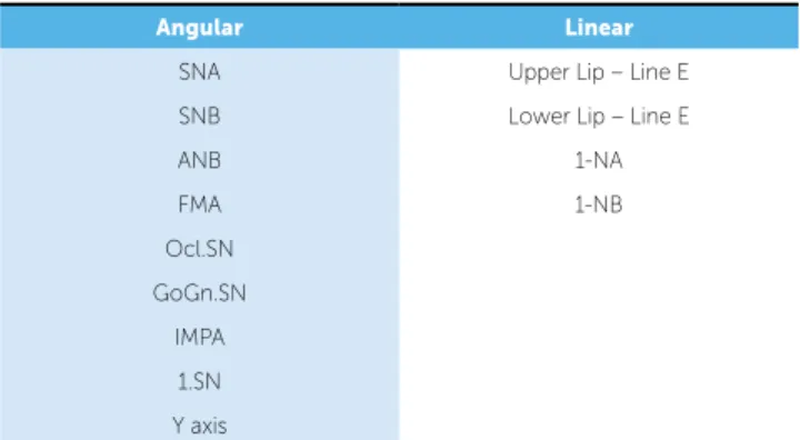
The 2D image analyses were performed using the mod-ule Ceph Tracing of the Dolphin Sotware. In this research 13 common cephalometric measures were compared, 9 be-ing angular and 4 linear (Table 1), based on 14 cephalomet-ric references: Lateral and on the midsagittal plane.
The projection magniication could be corrected by the computer at the beginning of the tracing, marking two points on the ruler present in the 2D image, so that the program could adequate it to its real size.
The craniofacial structures were automatically drawn by the program as the cephalometric points were being marked. Ater all markings, the cephalogram and the re-sults from the measurements were automatically provided.
The porion point was considered the most superior point of the external auditory canal, since on the tomo-graphic image there is no similar reference to the me-chanical porion, present on the digital radiograph.
On a second step, 10 days ater making the cepha-lograms, 6 exams were randomly selected and analyzed again, to perform the reliability study.
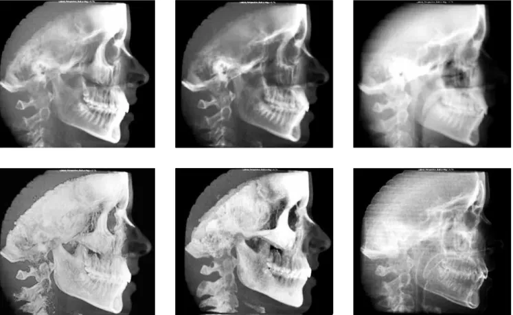
During the marking of points, image tools were used for better visualization of the structures, allowing altera-tions on the level of contrast, saturation and brightness. On the digital image, the possibility of inversion of colors allowed better visualization of bone structures (Fig 2).
On the simulated radiograph, there was the possi-bility of navigation among several ilters pre-deined by the sotware. Each ilter texture facilitates the visualiza-tion of bone structures, sot proile or teeth (Fig 3).
RESULTS
The descriptive statistical analysis including mean, median and standard deviation, was calculated for each cephalometric measure of the digital and simulated ra-diographs (Table 2).
Figure 1 - Image showing the auxiliary reference lines on the positioning of three-dimensional volumes.
Angular Linear
SNA Upper Lip – Line E SNB Lower Lip – Line E
ANB 1-NA
FMA 1-NB
Ocl.SN GoGn.SN
IMPA 1.SN Y axis
Axial
plane Axial
plane
Axial plane
Coronal plane
Coronal plane Midsagittal plane
Figure 2 - Diference between original and modiied images (inversion of colors).
The reliability study on the image capturing was de-termined by the repetition of six tracings (23%) ran-domly selected, performed in two diferent periods by the same examiner. The same point, lines, planes and measures were traced again ater a 10 day interval. The values obtained were compared by Intraclass Correla-tion Coeicient (ICC) and were between 0.969 and 0.999 with statistical signiicance of p < 0.05. Thus, the correlation was shown to be high, indicating reliability on the obtainment of measures.
The paired Student’s t test was used on the compari-son between the means of values found on the cepha-lometric tracings of digital and simulated radiographs, with a conidence interval of 95%.
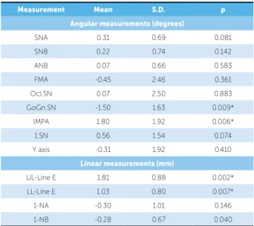
Most angular measures (78%) presented an irrele-vant diference between the means (0.07° - 0.56°), and only two measures presented a statistically signiicant diference (p < 0.05), GoGn.SN and IMPA, however the diference was 1.8° and 1.5° respectively.
The linear measurements presented two measures using teeth as reference that showed minimum difer-ence (0.28 mm and 0.30 mm, respectively) and two measures that used the lip as reference presenting difer-ences of up to 1.81 mm (p < 0.05) (Table 3).
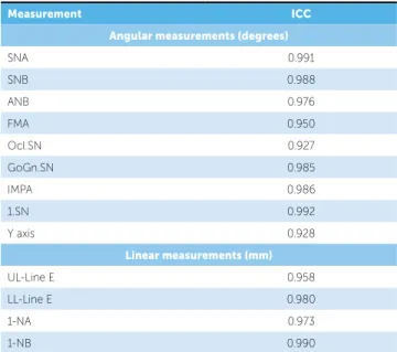
The Intraclass Correlation Coeicient between the two modalities of images in all the measurements in this work presented an index over 0.927, indicating a strong correlation, as can be seen on Table 4.
The statistical analysis was performed through the sotware SPSS 16.0 (SPSS Inc.,Chicago, Illinois).
DISCUSSION
The irst reports about computed tomography for den-tistry occurred in the late 90s.15 With the appearance of speciic sotwares, the possibility of simulating radiographs used in the orthodontic diagnosis such as panoramic, later-al and frontlater-al cephlater-alometric became promising especilater-ally because of the advantage of taking only one exam.
The validation of extracting two-dimensional images from three-dimensional images becomes extremely im-portant in this transition period or change of paradigm from the 2D to the 3D diagnosis, so that the clinician can continue to use the same cephalometric analysis, until three-dimensional analysis be established in the orthodontic literature and become available for the daily practice.14 At irst sight, the reconstruction of a 3D model and subsequent return to a 2D image seems paradoxical,
Measurement Mean Median S.D.
Angular measurements (degrees)
SNA Digital 82.71 82.70 3.65 3D 82.40 81.75 3.60
SNB Digital 80.06 79.75 3.56 3D 79.83 79.30 3.44
ANB Digital 2.66 2.40 2.27
3D 2.58 2.70 2.08
FMA Digital 24.13 24.70 5.97 3D 24.58 25.10 5.27
Ocl.SN Digital 14.16 14.85 4.56 3D 14.09 14.45 5.02
GoGn.SN Digital 29.72 30.35 7.03 3D 31.22 32.30 6.17
IMPA Digital 94.68 93.30 8.47 3D 92.88 91.70 7.58
1.SN Digital 104.77 103.75 8.77 3D 104.21 102.95 8.43
Y axis Digital 58.33 57.60 3.73 3D 58.65 58.80 3.65
Linear measurements (mm)
UL-Line E Digital -3.41 -3.55 2.35 3D -5.23 -5.20 2.08
LL-Line E Digital -0.46 -0.15 2.97 3D -1.50 -1.90 2.78
1-NA Digital 5.40 5.25 3.25
3D 5.70 4.80 3.01
1-NB Digital 5.76 5.60 3.17
3D 6.05 6.05 3.17
Table 2 - Descriptive analysis of linear and angular measurements, including mean, median and standard deviation, of each cephalometric measurement.
Table 3 - Diference between mean and standard deviation of angular and linear cephalometric measurements, carried on digital radiographs simulated from CBCT.
Measurement Mean S.D. p
Angular measurements (degrees)
SNA 0.31 0.69 0.081
SNB 0.22 0.74 0.142
ANB 0.07 0.66 0.583
FMA -0.45 2.46 0.361
Ocl.SN 0.07 2.50 0.883
GoGn.SN -1.50 1.63 0.009*
IMPA 1.80 1.92 0.006*
1.SN 0.56 1.54 0.074
Y axis -0.31 1.92 0.410
Linear measurements (mm)
UL-Line E 1.81 0.88 0.002* LL-Line E 1.03 0.80 0.007*
1-NA -0.30 1.01 0.146
1-NB -0.28 0.67 0.040
but this can make the progressive introduction of CBCT easier to the practice of the orthodontist and research.
Before the employment of cephalometric radiographs simulated from computed tomography, the evaluation of the reliability of the data of the new images is necessary, and this was the objective of the present study.
Some cephalometric points as Gonion and Porion that are used to deine the mandibular plane and the Frankfurt horizontal plane, respectively, are located in curved surfaces, which can make the identiication more diicult. For this reason, such points have consid-erable margin of error when marked.16-20
The results of comparison between the modali-ties of images showed statistically signiicant diference (p < 0.05) in two angular measures (IMPA and GoGn.SN) and in two linear measures (UL-Line E and LL-Line E). These 4 measures presented diferences of ± 1.8 mm or 1.8°. These diferences are probably clinically irrelevant. The two angular measures that presented statisti-cal diference used the mandibular plane as reference and the diference between mandibular contours on the two modalities of images can be noticed, which probably contributed to the diference between the two measurements (Fig 4).
In a similar work, the angular measure that pre-sented diferences was the FMA (-4.36°) that also uses the mandibular plane as one of the cephalometric refer-ences. However, when the anatomic porion could not be determined, the most superior part of the image of the auricular positioner (mechanical porion) was used as reference;9 on the present study all markings were per-formed on the anatomic porion.
The linear measures that had statistical diference in-volved lips and E Line (nose tip, sot pogonion). Some hypotheses must be considered in this regard: First, it cannot be assured that the positioning of the lips was ex-actly the same in both exams; then, the tomography is not the most recommended exam to reproduce sot tis-sues with high accuracy; and last but not least, the grav-ity working on sot tissues, when medical or cone beam tomographs are taken with the patient lying dorsally, and the same method used in the present work.
Figure 4 - Illustration of images: A) 3D image in a right proile visualization; B) perspective simulated cephalometric radiograph, with 100 mm ruler on the right; C) digital cephalometric radiograph.
Table 4 - Intraclass correlation coeicient between measurements carried on digital radiographs simulated from CBCT (n = 26).
Measurement ICC
Angular measurements (degrees)
SNA 0.991
SNB 0.988
ANB 0.976
FMA 0.950
Ocl.SN 0.927
GoGn.SN 0.985
IMPA 0.986
1.SN 0.992
Y axis 0.928
Linear measurements (mm)
UL-Line E 0.958
LL-Line E 0.980
1-NA 0.973
1-NB 0.990
The stability of the points is afected by several fac-tors. On the lateral radiograph, when the head is devi-ated from the exact proile position, the sagittal points experience the minimum degree of displacement, while the structures located outside the midsagittal plane change position signiicantly. In this case, structures in opposite sides of the head move in opposite directions.21 The questioning about the validity of the two-dimensional cephalometry in orthodontics is due to four aspects: First, the limitation of the 2D technique in representing a three-dimensional object. When a three-dimensional object is represented in two dimen-sions, the structures are vertical and horizontally dis-placed proportionally to the distance to the ilm or re-cord plane; then, symmetry on the right and let side is very rare, which makes it diicult to evaluate patients with craniofacial anomalies and facial asymmetries; third, the problems inherent to obtaining the image; and fourth, the operational error on the elaboration of the cephalogram and on the process of cephalometric analysis. Despite the amount of variables that compete to make the cephalometric analysis liable, it remains widely used by orthodontist from all around the world and, in many cases, it is essential for the diagnosis and treatment of patients.
Cephalometric analysis is still the only practical quantitative method that allows the investigation and evaluation of the relations between skull, dental and soft-tissue structures.22-25
The conventional radiography, as well as the per-spective simulated image, show a superimposition of bilateral structures that does not correspond to real-ity. It is taught that the structures on the let must be traced for being closer to the ilm and consequently ex-perience lower magniication than those on the right. Probably this error was repeated numerous times until the advent of the tomography. Figure 4 shows one pa-tient from the sample, that clinically did not present any remarkable facial asymmetry and ater position-ing the exams on the Dolphin sotware, it was noticed that the let side showed to be larger. However, as the magniication on the right side (closer to the frame) is larger, what is observed is an almost complete over-lap of the mandibular planes on both sides, suggest-ing symmetry. It would be necessary, however, three-dimensional visualization to be sure on which side is larger or smaller in cases of evident asymmetry.
The positioning of the patient is considered a crit-ical factor for cephalometric analysis.26,27 When the conventional exam is performed, the technician uses reference lines on the tissue, which can complicate the reproducibility. On CBCT, there is the advan-tage of visualizing only bone structures that can be used to reorient the patient on a better position with greater reproducibility.
Since the research was about a comparison to digi-tal radiographs, that had divergence on X-ray beam and consequently, magniication of the image size, the radiographs from tomographies, were also simulated with divergence on X-rays and magniication. The magniication factor is the amount of magniication of the image on the midsagittal plane and it was deined in 9.7% following orientation from the manufacturer of the Dolphin sotware. Some researchers used mag-niication factor of 7.5% justiied by the relation be-tween distance object-ilm and distance x-ray source-object.1,9 However this calculation cannot be surely used, since some patients who take radiographs in two diferent x-ray devices have radiographs with diferent size structures, but the distances from the focus to the object and from the object to the ilm are similar.
Considering the values related to radiation that the patient absorbs,28 the substitution of panoramic radio-graph for CBCT would not be justiied, panoramic ra-diographs solely could be appropriate for the diagnosis. But, in the case of orthodontic diagnosis, the substitu-tion of panoramic, lateral and frontal cephalometric ra-diographs for the CBCT can be done, so that the dos-age of NewTom 3G with a 12-in FOV, for example, it is approximately two times the dosage of conventional expositions, except for the full periapical exam.
Although some authors propose three-dimension-al cephthree-dimension-alometric anthree-dimension-alysis23,29,30 it is believed that the 3D analysis, in clinical practice, is a lot more qualita-tive, with spatial visualization and relation between the structures, than quantitative, with preestablished mea-sures; this last one is preferred for the research ield.
CONCLUSION
1. Kumar V, Ludlow JB, Mol A, Cevidanes L. Comparison of conventional and cone beam CT synthesized cephalograms. Dentomaxillofac Radiol. 2007;36(5):263-9.
2. Moshiri M, Scarfe WC, Hilgers ML, Scheetz JP, Silveira AM, Farman AG. Accuracy of linear measurements from imaging plate and lateral cephalometric images derived from cone-beam computed tomography. Am J Orthod Dentofacial Orthop. 2007;132(4):550-60.
3. Collins J, Shah A, McCarthy C, Sandler J. Comparison of measurements from photographed lateral cephalograms and scanned cephalograms. Am J Orthod Dentofacial Orthop. 2007;132(6):830-3.
4. Chen YJ, Chen SK, Huang HW, Yao CC, Chang HF. Reliability of landmark identiication in cephalometric radiography acquired by a storage phosphor imaging system. Dentomaxillofac Radiol. 2004;33(5):301-6.
5. Farman AG, Scarfe WC. Development of imaging selection criteria and procedures should precede cephalometric assessment with cone-beam computed tomography. Am J Orthod Dentofacial Orthop. 2006;130(2):257-65. 6. Mah J, Huang J, Bumann A. The cone-beam decision in orthodontics.
Proceedings of the 32nd Annual Moyers Symposium. Ann Arbor; 2006. p. 59-75. 7. Sarment DP. Dental applications for cone-beam computed tomography.
Proceedings of the 32nd Annual Moyers Symposium. Ann Arbor; 2006. 8. Swennen GR, Schutyser F. Three-dimensional cephalometry: spiral multi-slice
vs cone-beam computed tomography. Am J Orthod Dentofacial Orthop. 2006;130(3):410-6.
9. Kumar V, Ludlow J, Soares Cevidanes LH, Mol A. In vivo comparison of conventional and cone beam CT synthesized cephalograms. Angle Orthod. 2008;78(5):873-9.
10. Arai Y, Tammisalo E, Iwai K, Hashimoto K, Shinoda K. Development of a compact computed tomographic apparatus for dental use. Dentomaxillofac Radiol. 1999;28(4):245-8.
11. Hajeer MY, Millett DT, Ayoub AF, Siebert JP. Applications of 3D imaging in orthodontics: part I. J Orthod. 2004;31(1):62-70.
12. Hajeer MY, Millett DT, Ayoub AF, Siebert JP. Applications of 3D imaging in orthodontics: part II. J Orthod. 2004;31(2):154-62.
13. Ludlow JB, Davies-Ludlow LE, Brooks SL. Dosimetry of two extraoral direct digital imaging devices: NewTom cone beam CT and Orthophos Plus DS panoramic unit. Dentomaxillofac Radiol. 2003;32(4):229-34.
14. Motta AT. Avaliação da cirurgia de avanço mandibular por meio da superposição de modelos tridimensionais [tese]. Rio de Janeiro: Universidade Estadual do Rio de Janeiro; 2007.
15. Mozzo P, Procacci C, Tacconi A, Martini PT, Andreis IA. A new volumetric CT machine for dental imaging based on the cone-beam technique: preliminary results. Eur Radiol. 1998;8(9):1558-64.
REFERENCES
16. Athanasiou AE, Miethke R, Van der Meij AJ. Random errors in localization of landmarks in postero-anterior cephalograms. Br J Orthod.
1999;26(4):273-84.
17. Ludlow JB, Laster WS, See M, Bailey LJ, Hershey HG. Accuracy of measurements of mandibular anatomy in cone beam computed tomography images. Oral Surg Oral Med Oral Pathol Oral Radiol Endod. 2007;103(4):534-42.
18. Chate RA. Cephalometric landmark identiication within the petrous temporal region. Br J Orthod. 1987;14(1):33-41.
19. Adenwalla ST, Kronman JH, Attarzadeh F. Porion and condyle as cephalometric landmarks: an error study. Am J Orthod Dentofacial Orthop. 1988;94(5):411-5.
20. Houston WJ. The analysis of errors in orthodontic measurements. Am J Orthod. 1983;83(5):382-90.
21. Steiner CC. Cephalometrics for you and me. Am J Orthod Dentofacial Orthop. 1953;39(10):729-55.
22. Honda K, Arai Y, Kashima M, Takano Y, Sawada K, Ejima K, et al. Evaluation of the usefulness of the limited cone-beam CT (3DX) in the assessment of the thickness of the roof of the glenoid fossa of the temporomandibular joint. Dentomaxillofac Radiol. 2004;33(6):391-5. 23. Lagravere MO, Hansen L, Harzer W, Major PW. Plane orientation
for standardization in 3-dimensional cephalometric analysis with computerized tomography imaging. Am J Orthod Dentofacial Orthop. 2006;129(5):601-4.
24. Papadopoulos MA, Christou PK, Athanasiou AE, Boettcher P, Zeilhofer HF, Sader R, et al. Three-dimensional craniofacial reconstruction imaging. Oral Surg Oral Med Oral Pathol Oral Radiol Endod. 2002;93(4):382-93. 25. Quintero JC, Trosien A, Hatcher D, Kapila S. Craniofacial imaging
in orthodontics: historical perspective, current status, and future developments. Angle Orthod. 1999;69(6):491-506.
26. Cohen AM. Uncertainty in cephalometrics. Br J Orthod. 1984;11(1):44-8. 27. Yoon YJ, Kim KS, Hwang MS, Kim HJ, Choi EH, Kim KW. Efect of
head rotation on lateral cephalometric radiographs. Angle Orthod. 2001;71(5):396-403.
28. Ludlow JB, Davies-Ludlow LE, Brooks SL, Howerton WB. Dosimetry of 3 CBCT devices for oral and maxillofacial radiology: CB Mercuray, NewTom 3G and i-CAT. Dentomaxillofac Radiol. 2006;35(4):219-26.
29. Park SH, Yu HS, Kim KD, Lee KJ, Baik HS. A proposal for a new analysis of craniofacial morphology by 3-dimensional computed tomography. Am J Orthod Dentofacial Orthop. 2006;129(5):600.e23-34.