EXPERIMENTAL AND NUMERICAL STUDY ON
COMBUSTION OF BALED BIOMASS IN CIGAR BURNERS
AND EFFECTS OF FLUE GAS RE-CIRCULATION
by
Aleksandar M. ERI]a*, Stevan Dj. NEMODAa, Dragoljub V. DAKI]b, Branislav S. REPI]a
, and Dejan M. DJUROVI]a
a Laboratory for Thermal Engineering and Energy, Vinca Institute of Nuclear Sciences,
University of Belgrade, Belgrade, Serbia
b Innovation Centre, Faculty of Mechanical Engineering,
University of Belgrade, Belgrade, Serbia
Original scientific paper DOI: 10.2298/TSCI150827207E
The paperpresents results of experimental and numerical investigation addressing combustion of baled agricultural biomass in a 50 kW experimental furnace equipped with cigar burners. Experiments performed included measurements of all parameters deemed important for mass and energy balance, as well as parameters defining quality of the combustion process. Experimental results were compared with results of numerical simulations performed with previously developed CFD model. The model takes into account complex thermo mechanical combustion pro-cesses occurring in a porous layer of biomass bales and the surrounding fluid. The combustion process and the corresponding model were deemed stationary. Com-parison of experimental and numerical results obtained through research pre-sented in this paper showed satisfactory correspondence, leading to the conclu-sion that the model developed could be used for analysis of different effects associ-ated with variations in process parameters and/or structural modifications in in-dustrial biomass facilities. Mathematical model developed was also utilized to ex-amine the impact of flue gas re-circulation on maximum temperatures in the com-bustion chamber. Gas re-circulation was found to have positive effect on the tion of maximum temperature in the combustion chamber, as well as on the reduc-tion of maximum temperature zone in the chamber. The conclusions made provided valuable inputs towards prevention of biomass ash sintering, which occurs at high-er temphigh-eratures and negatively affects biomass combustion process.
Key words: biomass, combustion, experimental and numerical investigation, re-circulation
Introduction
Biomass combustion in cigar burners is considered new and still undeveloped tech-nology [1-4]. Several experimental installations with cigar burners have been designed, con-structed, and built in the Laboratory for Thermal Engineering and Energy, in Vinca Institute of Nuclear Sciences, Belgrade, Serbia, with an aim to examine combustion of baled biomass in cigar burners. The largest and the most important facility is a 1.5 MW industrial demon-stration boiler installed in the Belgrade agricultural complex PKB. The boiler is designed to
––––––––––––––
combust waste soybean, wheat, corn stover, and straw bales so as to provide energy needed for heating 1 ha of PKB greenhouses [2, 3].
Fuel (baled biomass) enters the furnace continuously, with drying, devolatilization, and char combustion zones forming in the bale. Complexity of transport processes that contrib-ute to the formation of the mentioned zones is additionally increased by the fact that combustion processes take place in a porous layer. Char combustion takes place at the top of the bale i. e. in the zone characterized by the highest temperature. Although being suitable for combustion pro-cesses, this zone is also quite unfavorable due to the problems associated with biomass ash melting. Ash melting issues are especially pronounced in case of agricultural biomass, primarily in wheat straw combustion, where ash melting starts at temperatures below 800 °C (which is experimentally confirmed using standard laboratory methods, CEN/TS 15370-1, 2006) [5]. In order to prevent this unfavorable phenomenon, maximum temperature in the combustion cham-ber or the size of maximum temperature zone needs to be reduced. One way to achieve this goal is to introduce cold re-circulation gas in the char combustion zone. This results in lower amount of excess air and formation of reducing atmosphere in the combustion chamber, in that manner reducing the temperature in the chamber and increasing the content of CO in the flue gas. In or-der to achieve conditions necessary for complete combustion of unburned flue gas components, additional air is later introduced into the combustion chamber.
In addition, in order to analyze biomass combustion process and assess the impact of flue gas re-circulation on the maximum temperature in the combustion chamber, a special ex-perimental installation was designed and constructed. The corresponding mathematical model was developed and verified through comparison of numerical results and experimental findings. The mathematical model was used to examine effects of different gas re-circulation rates on the reduction of maximum combustion temperature. Results obtained are deemed to be of great im-portance for optimization of combustion process in furnaces equipped with cigar burners.
Experimental investigation
Experimental facility used to investi-gate combustion of baled agricultural bio-mass is shown in fig. 1. Experimental fur-nace was adapted so as to be suitable for burning small biomass bales. Baled bio-mass (item 4) is fed into the thermally in-sulated furnace by the means of ball screw feeder (5). Once in the furnace, the bale rests on a grid (2). Air needed for fuel combustion is introduced through air dis-tributors (3, 9), whereby air flow is regu-lated by the means of flaps (8). The ratio of combustion air to re-circulated flue gas (re-circulation rate) is controlled by control valves (10). Combustion fluid is transported by the means of a fan (13, 14). In order to determine temperature profile in the bale and gain insight into the combustion process characteristics, a thermocouple was attached to the bale and in-troduced into the combustion chamber together with the bale. The resulting temperature pro-file was used to verify mathematical model developed to simulate the process examined.
During the experimental investigations the following input parameters were measured: (a) air mass flow rate at the upper and lower entrance, m1, m2, respectively, (b) fuel mass flow
rate (baled corn stover) mfu, and (c) flue gas temperature in the furnace T1-T6; (d) composition of dry flue gas in the outlet cross-section of the modeled area (CO2, O2, CO, NO).
The fuel is fed into the furnace in a quasicontinuous manner, meaning that the bale travels towards the combustion furnace during one portion of the one minute period, while resting during the remaining portion of the same one minute period. Relative position of the bale in relation to the entrance into the combustion chamber was therefore determined, as well as related time period needed for the bale to pass that particular distance. Data collected ena-bled the mean fuel mass flow rate mfu to be determined. In addition, temperature field in the central cross-sectional area of the corn stover bale placed in the furnace was also determined. Four thermocouples were installed along the central vertical plane of the bale, measuring re-spective temperatures in the stationary combustion regime.
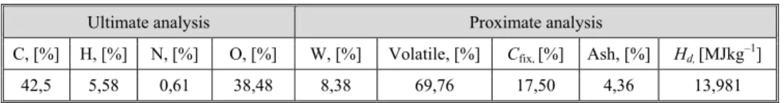
Experimental investigation was conducted with corn stover used as an experimental fuel. Corn stover represents the most common renewable agricultural fuel in Serbia, and should be find way to make it usable for exploitation. Experiments were performed under the assumption that porosity of the fuel sample in the test section of the apparatus corresponds to the porosity of the fuel under real combustion conditions. The bales used in the investigation performed have had the size of 0.35 × 0.45 × 0.80 m, density of pressing of 92 kg/m3 and po-rosity of 0.65. Ultimate and proximate analysis of experimental fuel is given in tab. 1. Fuel and air flow rates are presented in tab. 2.
Table 1. Ultimate and proximate analysis of corn stover
Mathematical model
Development of appropriate mathematical model requires a set of appropriate equations which define velocity, concentration and temperature fields to be set-up. Each of these equations is de-fined in the form of well-known CFD transport equations. It is important to emphasize that some of
the transport equations defining turbulent flow in porous media are different from the equa-tions developed for the fluid environment. For the said reason, these two sets of equaequa-tions need to be defined separately. However, before defining the model, certain assumptions need to be made in order to simplify the calculation, but without great affecting the end result. Thus, the following assumptions have been made:
– model is stationary and assumes constant position of the combustion front in relation to the combustion chamber, the fuel enters the furnace in a manner shown in fig. 1;
– feeding of the fuel into the combustion chamber is approximated by volumetric sources of different fuel constituents defined only for the porous zone of balled biomass;
– source intensity is defined based on desired furnace output;
– porous medium is deemed homogeneous, with constant characteristics (porosity, permea-bility, conductivity) since mass is uniformly distributed throughout the entire volume of the porous layer;
Ultimate analysis Proximate analysis
C, [%] H, [%] N, [%] O, [%] W, [%] Volatile, [%] Cfix, [%] Ash, [%] Hd, [MJkg–1]
42,5 5,58 0,61 38,48 8,38 69,76 17,50 4,36 13,981
Table 2. Fuel and air flow rates
Unit
Air mass flow
rate, [kgs–1] Fuel mass
flow rate, [kgs–1]
Upper inlet
Lower inlet
– it is assumed that the source of water vapor released by drying is uniformly distributed throughout the volume of the porous layer; however, energy used for drying is modeled based on the experimental findings;
– it is assumed that combustion in porous and fluid environment is laminar; – Arrhenius model was used to define the rate of chemical reactions; and – it is assumed that volatiles consist of propane, CO2 and water vapor.
Equations describing velocity, concentration and temperature fields were then de-fined based on the assumptions made. The equations were set for the entire domain, which in-cluded the porous biomass bale and the fluid environment surrounding the bale. Domain of the mathematical model is indicated by dotted lines in fig. 2. Transport processes were mod-eled by assuming that flow regimes in both environments were turbulent, where turbulence
was modeled using the widespread and generally ac-cepted k-ε turbulence model. A continuity equation rep-resents the simplest transport equation, where the un-steady term was omitted due to the stationarity of the case examined. Cross-sectional velocity in the porous layer corresponds substantially to the velocity in the flu-id environment [3, 6, 7], meaning that continuity equa-tion, which applies to the porous and the fluid environ-ment, may be expressed in the following manner:
( ) c
i
f j S
x ρ W
∂ =
∂ (1)
where Sc is the source member defined by boundary conditions, i, j = 1, 2for 2-D case, and Wj is the velocity component (W1 and W2).
In order to be able to define velocity field, it is necessary to define the momentum equation, eq. (2), which differs for fluid and the porous media. While momentum equation for fluid environment takes its usual form, momentum equation for po-rous media comprises an additional member, which accounts for a pressure drop occurring as a result of fluid flow through the porous media. This pressure drop is usually defined by Forchheimer's equation which, in case of higher velocities, implies a non-linear relation be-tween fluid velocity and pressure gradient [3, 6, 7]:
eff eff
1 2
( ) j i f i i
i i i
f i j
j
W
x x x K
p
W W W W W
x K
µ
µ ρ
ρ ∂
∂ ∂
= − − +
∂ ∂ ∂
⎛ ⎞ ∂ ⎛ ⎞
⎜ ⎟ ∂ ⎜ ⎟
⎝ ⎠
⎝ ⎠ (2)
In eq. (2) turbulent stresses are determined by the widespread k-ε model. It was also assumed that the turbulent viscosity coefficient in the porous area µε,t, is equal to the turbulent viscosity coefficient in the free fluid zone µk, meaning that their effective values are equal [3]. Coefficients, K1 and K2are Forchheimer’s equation coefficients which are determined
exper-imentally [6, 8-10].
The species concentration fields are defined through species transport equations. Similarly to momentum conservation equation defined for fluid flow, species transport equa-tion has its common form that includes diffusion, convecequa-tion, and source members. Based on
macroscopic examination of porous media and having in mind that the impact of the fluid where species transport occurs is taken into account through effective diffusion coefficient, the following expression may be written:
eff
( i k) k k
i i i
Y
W Y D R
x ρ x ρ x ε
⎛ ∂ ⎞
∂ = ∂ +
⎜ ⎟
∂ ∂ ⎝ ∂ ⎠ (3)
where Deff is the effective diffusion coefficient. By neglecting the turbulence range and
dis-persed turbulent diffusion, this coefficient is defined as:
, eff disp
1 t
m t
D D µε µ ε
ρ σ σ
⎛ ⎞
= + ⎜ + ⎟
⎝ ⎠ (4)
where m is the Schmidt number of molecular diffusion and Ddisp is mass dispersion
coeffi-cient which, according to Pedras and de Lemos [7] and de Lemos [11], can be determined:
disp k
m
D ρ µ C
σ
= (5)
where C is the model constant which, according to Pedras and de Lemos [7] and de Lemos [11], reaches approximately 100 for the flow conditions present in the case considered here in. However, for simplicity reasons and due to macroscopic approach related to the analysis of the fluid flow through porous media, the dispersed mass diffusivity has been neglected and the following has been adopted: µε= µ and µt,ε= µt. Thus, effective diffusion coefficient in the porous media becomes equal in the fluid flow:
) ,
( i k m k t k k
i i t i
Y
W Y D R
x x x
µ
ρ ρ ε
ρσ
⎡ ⎛ ⎞ ∂ ⎤
∂ = ∂ + +
⎢ ⎜ ⎟ ⎥
∂ ∂ ⎢⎣ ⎝ ⎠ ∂ ⎥⎦ (6)
The source member of this equation is multiplied by the porosity ε, because of the assumption that chemical reactions take place only in the porous cavity. The form of the source member Rk depends on the combustion process rate, as well as the stoichiometry of the process. Thus, the source member is defined based on the mentioned two parameters.
As far as the homogeneous reaction is concerned, literature data [12] reveal that modified Arrhenius's expression for the conversion components rates is often used:
1 , 1 exp ( ) R ν α ν ν ν = ∑ ⎛ ∆ ⎞ ⎛∏ ∏ ⎞ = − ⎜⎜− ⎟ ⎜⎜ ⎟⎟ ⎟ ⎝ ⎠ ⎝ ⎠
i rik pik
i
m
i
k k pik rik i
g c i
E
R M A T c c
T K (7)
where Rk is the component k conversion rate, m – the number of chemical reactions, Ai – the prior to exponential coefficient for the reaction i, ai – the temperature coefficient, ∆E – activa-tion energy for the reacactiva-tion i, νpik, and νrik are stoichiometric numbers of products and reactants for the reaction i and component k, respectively, where the following requirement has to be met:
1 1
m m
k pik k k rik k
A A
ν
ν
= =
∑ =∑ (8)
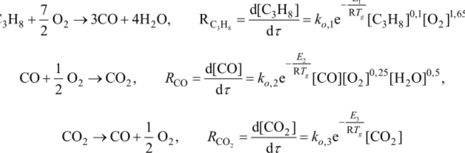
In order to model the volatiles combustion, while taking into account the assump-tions related to volatile composition, the two-stage reversible propane combustion reaction was adopted, yields:
1
3 8
R 0,1 1,65 3 8
3 8 2 2 C H ,1 3 8 2
d[C H 7
C H O 3CO 4H O, R e [C H [O
2 d ] ] ] , g E T o k τ − + → + = = 2
R 0, 25 0,5
2 2 CO ,2 2 2
1 d[CO]
CO O CO , e [CO][O ] [H O]
2 d ,
g E T o R k τ − + → = = 3 2 R 2
2 2 CO ,3 2
d[CO 1
CO CO O e [CO
2 d
]
, g ]
E T o R k τ − → + = =
Char combustion was modelled using the following two-step reaction:
4 R
2 C ,4 2
1 d[C]
C O CO e [C][O
2 d ]
g E T o R k τ − + → = =
In this manner, the rates of combustion reactions in the proposed model have been defined. Source mem-bers of species conservation equations are shown in tab. 3. Formation of NO is mod-eled by taking into account all four formation mecha-nisms: prompt, thermal, fu-el, and formation of inter-mediate species. The source members of species trans-port equations describing the formation of NO are shown in tab. 4. Discretiza-tion of defined equaDiscretiza-tions and their solving was per-formed by the means of FLUENT software. Results obtained are presented in the following section of this paper.
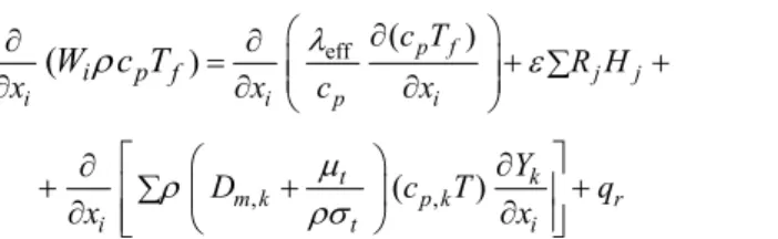
In order to define the temperature field, energy conservation equations needs to be specified both for the fluid and the porous media. Energy conservation equation in porous media is defined in a similar manner as in case of species concentration fields. In this case, the porous media is considered to be a fluid flow where the influence of porous media is reflected through effective thermal conductivity (single phase model) [3]. It is assumed that the effec-tive diffusion coefficient of gases in the porous media, responsible for transmitting heat re-sulting from gas diffusion, is the same as effective diffusion coefficient in the fluid flow. Hence, the energy conservation equation for porous media is defined:
Table 3. Source member of the species conservation equations
Species Source member
C3H8 −RC H3 8
CO 3 8 2
3 8 2
CO CO CO
C H CO CO C
C H CO C
3 M R R M R M R
M − +M + M
O2
2 2 2 2
3 8 2
3 8 2
O O O O
C H CO C CO
C H CO C CO
7 1 1
2 2 2
M M M M
R R R R
M M M M
− − − +
H2O
2 3 8 3 8 H O C H C H
4 M R
M
C −RC
CO2 2 2
eff ( ) )
(
ρ
⎛λ ∂ ⎞ ε∂ ∂ = ⎜⎜ ⎟⎟+ ∑ + ∂ ∂ ⎝ ∂ ⎠ p i j f j
i p i
i p f
c T
R H
x
W
c T
x c x, ( , ) µ ρ ρσ ⎡ ⎛ ⎞ ∂ ⎤ ∂ +∂ ⎢∑ ⎜ + ⎟ ∂ ⎥+ ⎢ ⎝ ⎠ ⎥ ⎣ ⎦ t k
m k p k r
i t i
Y
D c T q
x x (9)
Effective thermal conductivity of the fluid flowing through porous media has been an-alysed in great detail in the literature [3, 12, 13], where the importance of stagnant and dis-persed thermal conductivity has been emphasized. Similar to the diffusion coefficient considera-tions described earlier, the impact of dispersed thermal conductivity was assumed to be negligi-ble, due to the fact that at high temperatures and due to thermos physical properties of gases, stagnant thermal conductivity prevails. Thus, the effective heat transfer coefficient is defined:
eff f s
(1
)
λ =λ ε λ+
−
ε
(10)where λs is the thermal conductivity coefficient of the porous solid matrix, or in this case, corn stover residue, whose value is determined experimentally.
Table 4. Source member in ۼ۽ forming equation
The last member in the energy conservation equation reflects the radiation energy transfer occurring in the gas flow. This member is defined by P1 model of FLUENT 6 CFD package, and is presented in somewhat altered form due to the assumption related to the zero external radiation: 1 3( ) r s s q G
a σ Cσ
= − ∇
− − (11)
Species Source member
NOt
2 ,1 , 2
,1 2 , 2 2 ,1
, 2 2 ,3 2 ,1 [NO] 1 [N [O [NO] 1 [O [O ] ] ] ] ] H 2 [O][N r r f f r f f f k k k k k k k k − + +
NOp [O2]a[N [CH e2] 4] Ea/RT
pr
k −
NOf, HCN 1/ R 2/ R
1[HCN][O2] e 2[HCN][NO]e
E T E T
a
A − −A −
NOf, NH3 1/ R 2/ R
1[NH [O3] 2] e 2[NH [NO]e3]
E T E T
a
A − −A −
HCN C H3 8 N HCN
N
R Y M
M
NH3 3 8 3
N NH C H
N
R Y M
where G is the incoming radiation in the final volume. Additional transport equation has been assembled for determination of G member. This transport equation was processed together with all other transport equations defined in the model presented.
2 4
4 σ
⎛ ⎞
∂ ∂
= −
⎜ ⎟
∂ i ⎝ ∂ i ⎠
G
Γ aG an T
x x (12)
Emission coefficient (a) in the radiation energy equation, eq. (12) is determined by the weighted-sum-of-gray-gases model, which is expressed:
ln 1( mr) a
s −
= − (13)
Numerical procedure
The previously specified equations enabled the mathematical model describing combustion of baled corn stover residue in the combustion chamber of defined construction features to be completed. Partial differential equations comprising the said mathematical model were non-linear and mutually coupled. Numerical procedure applied for equation solv-ing was based on the use of the control volume method, includsolv-ing implementation of collo-cated numerical grid for momentum equations, hybrid numerical scheme (the combination of upstream and central differencing), and SIMPLE equation solving algorithm. The final stabi-lization iteration was performed by sub-relaxation method. Calculation procedure and the numerical method applied are described in more detail in the literature [14].
The first set of partial differential equations describing combustion of baled corn stover residue has been solved using the adapted version of the open finite-volume CFD-code FASTEST-2D, with specially developed modules for modeling combustion in porous matrix, as well in the surrounding turbulent flow. Mathematical model developed included a mesh set comprised 441,480 equal volumes.
Experimental results
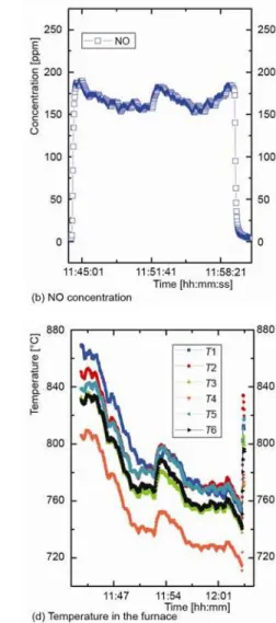
Experimental results obtained in the selected time interval during stationary operat-ing regime are shown in fig. 3. The results obtained indicate that duroperat-ing the selected stationary regime, high quality combustion process was achieved. Good thermal isolation and high com-bustion temperatures of about 780 °C resulted in low content of CO in the flue gas, reaching approximately 40-50 ppm. Also, CO2 and O2 levels were found to be within the expected
range, so that the excess air was found to be about two.
Figure 3. Experimental diagrams
Model results
veloc-ity and temperature fields have been obtained, as well as CO, CO2, NO, O2, and Cs
concentra-tion fields in the combusconcentra-tion chamber. Analysis performed enabled certain conclusions to be made, which contributed to better understanding of biomass combustion process and pointed out possible construction improvements in biomass combustion facilities.
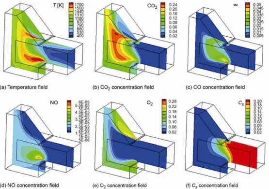
Figure 4. Results of numerical simulation of biomass combustion (combustion without re-circulation)
In addition to the temperature and velocity fields, concentrations of certain flue gas components represent one of the most important aspects of combustion process. From the envi-ronmental point of view, the greatest polluting impact is attributed to emissions of CO and NO. Bearing in mind that sulfur content in the biomass is negligibly low, CO and NO are the most important air pollutants generated during biomass combustion. Therefore, design of any biomass plant must include all necessary technical measures aimed at reduction of CO and NO emissions. Since CO is formed at low temperatures or during combustion in ambient character-ized by insufficient O2 content, it is very important to keep combustion temperature at high
enough levels and to provide good mixing of O2 and combustion products. Sometimes good O2
and flue gas mixing may be difficult to achieve, since turbulent molecular diffusion of O2 may
be insufficient to provide high O2 concentration in the combustion zone. In these cases,
con-struction modifications are necessary. The most commonly applied modification is aimed at prolonging the flue gas retention time in the high temperature zone, thereby enabling sufficient time for O2 and fuel mixing and achievement of complete combustion. This solution involves
ob-served from fig. 4(c) which indicates that the most intensive formation of CO occurs in the zone near the entrance of the combustion chamber. In this zone, temperatures are high enough (~1200 K), as indicated in fig. 4(a), but the O2 concentration is very low, fig. 4(e), which leads
to the conclusion that O2 diffusion is the main mechanism responsible for CO formation. It
should be kept in mind that high temperatures in the considered area are very favorable for de-velopment of reverse endothermic reactions associated with CO2 decomposition to CO and O2,
which further increases the problem.
The NO is another harmful combustion product which occurs due to high O2 content
and presence of high temperature zones. The NO concentration fields shown in fig. 4(d) indicate that the zone with the most intensive formation of NO fits the high temperature zone, fig. 4(a). In the same time, the zone with the most intensive NO formation is limited to the zone where the gradient of O2 is high, fig. 4(e). Unlike CO, NO cannot be removed by providing special
combustion conditions after NO is formed. Therefore, special attention must be given to the formation of NO, implementing measures aimed at reduced NO formation. This is accom-plished by reducing the temperature and O2 concentration in the combustion zone by the means
of cold flue gas re-circulation.
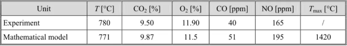
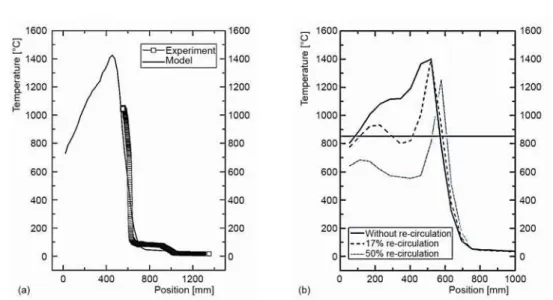
Model verification
Table 5 shows comparison of experimental data with results obtained through imple-mentation of mathematical model developed, indicating good agreement between the two set of data. Also, good agreement can be observed from the diagram presented in fig. 5(a), which ex-hibits temperature profiles obtained by measurements as well as though implementation of de-veloped model. Maximum temperature in the furnace could not be measured due to the limita-tion imposed upon maximum temperature measurable by the measurement chain used (compris-ing K-type thermocouple, temperature data acquisition system and computer software), which equaled 1200 °C. Based on the collected data, it is concluded that biomass combustion model is successfully verified, so that parametric study on the impact of flue gas circulation on the re-duction of maximum temperature in the combustion chamber can be performed.
Table 5. Comparison of numerical and experimental results
Differences of the results in the measurements and the mathematical model can be seen in tab. 5. These differences may be acceptable, because they are in the range of the ex-tended measurement uncertainty of the measuring equipment.
Analysis of cold flue gas re-circulation
Analysis is performed in order to evaluate the effects of cold flue gas re-circulation on the reduction of maximum temperature in the combustion chamber. The study was cducted using the previously described 3-D computer model. Cold flue gas was introduced on-ly through the lower air intakes, since it was assumed that such air intake had the most pro-nounced effect. Three air re-circulation cases were considered: (1) zero flue gas re-circulation, (2) 17% flue gas re-circulation, and (3) 50% flue gas re-circulation. Table 6 shows input pa-rameters for all three cases addressed.
Unit T [°C] CO2[%] O2[%] CO [ppm] NO [ppm] Tmax [°C]
Experiment 780 9.50 11.90 40 165 /
Figure 5. Temperature profile in the bale; (a) temperature profile in the bale, (b) temperature in central axis of the bale
Table 6. Input parameters
*
Only at the lower entrance
After conducting numerical simulation, several conclusions have been derived. Flue gas re-circulation is convenient in terms of reducing concentration of nitrogen oxides in the flue gas, as seen in tab. 7. Also, a positive effect on the reduced size of the zone with tempera-ture higher than 850 °C is observed. Figure 5(b) shows the width of the zone with temperatempera-ture higher than 850 °C for all three examined cases, where the zone width was measured relative to the central axis of the biomass bale. It may be noted that increased re-circulation results in reduced width of the high temperature zone. Thus, it is concluded that combustion of biomass characterized by low ash melting point must be performed with cold flue gas re-circulation.
Table 7 shows results of the combustion process simulation in the cigar burner, with analysis of the impact achieved by cold flue gas re-circulation. Results obtained indicate that excess air coefficient remained to be around 2, because gas flow at the entrance of combus tion chamber was increased. This reduces maximum temperature in the combustion chamber
Parameters Zero
re-circulation
17% re-circulation
50% re-circulation
Load [kW] 50 50 50
Mass flow in the upper entrance [kgs–1] 0.01 0.01 0.01
Mass flow in the lower entrance [kgs–1] 0.0145 0.0195 0.0395
Volume fraction of О2* – 0.232 0.1982 0.0914
Volume fraction of CO2* – 0.00 0.0234 0.0777
Volume fraction of CO* – 0 0 0
Table 7. Output parameters
and flue gas temperature at the exit of the combustion chamber. Beside these two, other com-bustion parameters remained at approximately the same level.
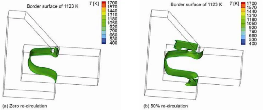
Figure 6 shows simulation of flue gas re-circulation effect when border surface tem-perature equals 850 °C (1123 K). The volume of the porous media, limited by the cold zone and the border surface, is safe from the ash sintering point of view, because temperatures de-veloping in the volume are lower than 850 °C. Also, as seen from the diagram, the size of the safe zone is set significantly higher when cold flue gas re-circulation is applied. This means that in the considered volume, ash sintering will certainly not occur. Although 50% flue gas re-circulation is difficult to achieve in practice, it’s been used in order to compare and evalu-ate the effects of cold flue gas re-circulation.
Figure 6. Border surface with temperature of 850 °C (1123 K)
Conclusions
Experimental investigation performed on specially developed experimental apparatus equipped with cigar burners and intended for combustion of biomass bales, indicate that corn stover remains, prepared in the form of bales, can be used for combustion. However, special at-tention must be paid to the ash sintering issues. Although in case of corn stover combustion this problem is not as pronounced as in the case of wheat straw combustion, problems may arise after longer period of boiler operation. Results obtained during experimental
investiga-Parameters Unit Zero
re-circulation
17% re-circulation
50% re-circulation
Max. temperature in the furnace [°C] 1577 1497 1453
Outlet temperature [°C] 771 733 615
Mass fraction of O2 – 0.10 0.0982 0.0914
Mass fraction of CO2 – 0.0911 0.095 0.098
Mass fraction of H2O – 0.0775 0.08 0.081
Mass fraction of CO – 5.1E-05 1.04E-04 0
tions performed on the apparatus designed for combustion of small biomass bales may prove to be of great importance when designing full-scale furnaces and estimating kinetics of combus-tion process in furnaces of various capacities. In addicombus-tion, results of experiments performed on specially designed installation provided valuable information on the impact of flue gas re-circulation on the reduction of maximum temperature in the combustion chamber, as well as reduction of nitrogen oxides concentration in the flue gas. Data obtained were used to verify the mathematical model developed to simulate analyzed case of biomass combustion.
The mathematical model was developed in such a way to enable simulation of bio-mass combustion in stationary operating regimes with sufficient accuracy and with acceptable description of physical phenomena. Numerical results obtained showed satisfactory agree-ment with experiagree-mental data, both with respect to flue gas temperature and flue gas composi-tion at the outlet cross seccomposi-tion of the combuscomposi-tion chamber, as well as in terms of temperature profiles developed in the central plane of the balled corn stover. It follows that developed 3-D model can be successfully used to simulate different working regimes of the considered fur-nace, as well as to simulate combustion of various baled biomass species. Parametric analysis performed showed that cold flue gas re-circulation reduces maximum temperature in the combustion chamber as well as maximum temperature zone. This is very important with re-spect to ash melting problems. At the same time, flue gas re-circulation also results in lower NO concentrations in the flue gas, which is very important from environmental point of view.
Further research should be directed towards the determination of kinetic parameters of biomass combustion and flue gas re-circulation impact on their change. This is a very im-portant issue during designing new furnaces, because of the aforementioned parameters de-pends the size of biomass burning zone, and hence the dimensions of the combustion cham-ber. In addition, it is necessary to consider other measures that reduced the emissions of NOx
into the atmosphere during combustion of agricultural biomass.
Acknowledgment
The authors would like to thank the Ministry of Education, Science and Technologi-cal Development of Serbia for funding the projects III 42011 Development and improvement of technologies for energy efficient and environmentally sound use of several types of agricul-tural and forest biomass and possible utilization for cogeneration and TR33042 Fluidized bed combustion facility improvements as a step forward in developing energy efficient and envi-ronmentally sound waste combustion technology in fluidized bed combustors.
Nomenclature
A – radiation absorption coefficient, [m–1]
c – molar concentration, [kmol·m–3]
cp – specific heat capacity, [kJkg–1K–1]
D – diffusivity, [m2s–1]
G – intensity of incoming radiation, [Wm–3]
Hd – lower heating value, [MJ/kg]
Hj – heating value of reaction j, [Jkg]
K1 – viscous permeability, [m2]
K2 – inertial permeability, [m]
Mk– molar mass of species k, [kg·mol–1]
p – pressure, [Pa]
R – components conversion rate, [kgm–3s–1]
S – source, [kgm–3s–1]
s – path length, [m]
W – velocity, [ms–1]
x – co-ordinate, [m]
Y – mass fraction, [–]
Greek symbols
Γ – diffusion coefficient, [–]
ε – porosity, [–]
λ – thermal conductivity, [WmK–1]
µ – dynamic viscosity, [Pa·s]
ν – stoichiometric number of moles, [–]
ρ – density, [kgm–3]
– time, [s]
References
[1] Bech, N., et al., Mathematical Modeling of Straw Bale Combustion in Cigar Burners, Energy & Fuels,
10 (1996), 2, pp. 276-283
[2] Mladenović, R., et al., Energy Production Facilities of Original Concept for Combustion of Soya Straw
Bales, Proceedings,16th European Biomass Conference & Exhibition – From Research to Industry and
Markets, Valencia, Spain, 2008, pp. 1260-1270
[3] Erić, A., Thermomechanical Processes Connected to Baled Soybean Residue Combustion in the Pushing
Furnace (in Serbian), Ph. D. thesis, Faculty of Mechanical Engineering, University of Belgrade, Bel-grade, 2010
[4] Miltner, M., et al., Process Simulation and CFD Calculations for the Development of an Innovative
Baled Biomass-Fired Combustion Chamber, Applied Thermal Engineering, 27 (2007), 7, pp. 1138–1143
[5] Repić, B. S., et al., Development of the Technology for Combustion of Large Bales using Local
Bio-mass, in: Sustainable Energy – Recent Studies (Ed. A. Gebremedhin), In Tech, Wiena, 2012, pp. 55-87
[6] Nemoda, S., et al., Numerical Simulation of Reacting Fluid Flow in Porous Media Applied on the
Bio-mass Combustion Research, Proceedings, 1st International Conference on Computational Mechanics
CM’04, Belgrade, 2004, pp. 1-8
[7] Pedras, M. H. J., de Lemos, M. S. J., Thermal Dispersion in Porous Media as a Function of the
Solid-Fluid Conductivity Ratio, International Journal of Heat and Mass Transfer, 51 (2008), 21-22, pp.
5359-5367
[8] Erić, A., et al., Experimental Method for Determining Forchheimer Equation Coefficients Related to
Flow of Air through the Bales of Soy Straw, International Journal of Heat and Mass Transfer, 54
(2011), 19-20, pp. 4300–4306
[9] Erić, A., et al., Determination of the Stagnant Thermal Conductivity of the Baled Soybean Residue (in
Serbian), Contemporary Agricultural Engineering, 36 (2010), 4, pp. 334-343
[10]Erić, A., et al., Experimental Determination Thermo Physical Characteristics of Balled Biomass, Energy,
45 (2012), 1, pp. 350-357
[11]de Lemos, M. J. S., Turbulence in Porous Media: Modeling and Applications, Elsevier, Amsterdam, The
Netherlands, 2006
[12]Kaviany, M., Principles of Heat Transfer in Porous Media, 2ed ed., Springer-Verlag, New York, N. Y.,
USA, 1999
[13]Nield, D. A., Bejan, A., Convection in Porous Media, Springer Science and Business Media, Inc., New
York, N. Y., USA, 2006
[14]Patankar, S. V., Numerical Heat Transfer and Fluid Flow, Hemisphere, New York, N. Y., USA, 1980