Inluence of Niobium and Molybdenum on Mechanical Strength and Wear Resistance of
Microalloyed Steels
André Itman Filhoa*, Rosana Vilarim da Silvab, Pedro Gabriel Bonella de Oliveiraa, João Batista
Ribeiro Martinsc, Waldek Wladimir Bose Filhod, Martin Strangwoode
Received: December 19, 2016; Revised: April 02, 2017; Accepted: May 21, 2017
The HSLA (High-Strength Low Alloy) steels are used in the production of pipes, langes and
connectors to build ducts for ore, oil and gas transport. The conventional processes are the rolling or forging. In the transport of ore and heavy oil, the abrasive particles impair the surfaces and reduce the pipelines lifetime. Therefore, besides the mechanical properties as API 5L, it is important to verify the wear resistance of these steels. In this context, two microalloyed steels were forged in the form of square bars. Thereafter, specimens of these bars were annealed at 930 ºC, quenched at 900 ºC and tempered at 600 ºC. Tensile and wear tests were performed. The results show that molybdenum and niobium
present similar efects on phase transformation of steels, promoting a desired acicular ferrite/bainite microstructure and fulill the mechanical strength of API 5L-X70 standard. The molybdenum has dominating efect in the hardenability when in solid solution, however, after tempering, thermodynamic
simulation by FactSage software indicates that niobium probably promotes secondary hardening.
Keywords: Steels containing niobium and molybdenum, Heat treatments, Mechanical strength of microalloyed steels, Wear tests of microalloyed steels, FactSage software
* e-mail: [email protected]
1. Introduction
API (American Petroleum Institute) steels are used on a large scale, mainly in the construction of pipelines and accessories to transport oil and natural gas. These pipelines operate at great depths and withstand pressures up to 350 bar
in the presence of chlorides, sulides and other dissolved ions1.
API steels are also used in the ore transportation; however, the inner walls of the pipes have low wear resistance, when in contact with slurries and abrasive particles2,3.
The conventional processing of API steels by rolling and forging allow a wide range of thicknesses with control of temperature and plastic deformation during the mechanical forming stages4. In forged materials, quenching and tempering
heat treatments are necessary to achieve the required mechanical properties.
The grain reining associated to the precipitation hardening by carbides, nitrides and carbonitrides inely dispersed in
the matrix are used to increase the mechanical properties. These microalloyed steels usually contain niobium, titanium and vanadium, which ensure good toughness and high tensile strength5,6. Additionally, the heat treatment control
of microalloyed steels forgings leads to the formation of non-polygonal or acicular ferrite as well as bainite, which further contribute to strengthening7.
Another chemical element used in these steels is the molybdenum that favors the generation of bainite at relatively
low cooling rates and promotes a iner microstructure8,9.
Molybdenum, together with chromium, plays a unique and
important role both by having a marked decreasing efect
on the austenite transformation temperature and by forming various carbides with complex constitutions in the steels10.
Studies have shown that chromium and molybdenum
introduce diferent stoichiometry of carbides according
to the chemical composition of the steels11. Therefore, in
industrial process, adding some molybdenum is a good
choice to meet the requirement of strength. The reinement
of austenite grains, the microstructure with grain boundary allotriomorphic ferrite, granular bainite and a uniformly dispersion of precipitates in the steel matrix are key aspects in the improvement of mechanical properties, hardness and wear resistance9,12. It has been asserted that HSLA steels
containing niobium and molybdenum produce a acicular
ferritic/bainitic structure with excellent strength-retention
characteristics at high temperatures in the range of 600 to a Master Program in Metallurgic and Materials Engineering (PROPEMM), Federal Institute of
Education, Science and Technology of Espírito Santo, Vitória, ES, Brazil
b MasterProgram in Sustainable Technologies (PPGTECS), Federal Institute of Education, Science and Technology of Espírito Santo, Vitória, ES, Brazil
c ArcelorMittal Tubarão, Serra, ES, Brasil
700 ºC, in comparison to conventional HSLA steels containing niobium and vanadium11,13.
The equipment and tools produced with microalloyed steels forgings are commonly subjected to abrasion by soil, sand, ore powder and so on during service4. The wear
is mainly controlled by the microscopic stress distribution and microstructure in the contact region12. The utilization of
proper materials and suitable heat treatment can enhance the wear resistance under the low stress abrasion and improve the service life of the relevant machinery.
Therefore, the present research aims to investigate
the hardness, mechanical strength, wear coeicient and
corresponding microstructures of microalloyed steels with
diferent levels of niobium and molybdenum after quenching and tempering. In order to understand the efects of carbide
precipitation in controlling the grain size, thermodynamic simulations with FactSage software were carried out to analyze the type and solubility temperatures of the precipitates formed in these steels.
2. Experimental Procedures
Two steels were manufactured in an induction furnace with a capacity of 200 kg. The liquid metal was poured into an ingot mold of cast iron with approximate size of 85x85x800 mm. The cast ingot was heated at 1050 ºC for two hours and forged in the form of square bars with 38 mm side. Two samples were obtained and analyzed in an optical emission spectrometer to determinate the chemical composition. The forged bars were heated at 930 ºC and cooled inside the furnace to homogenize the microstructure. Cubic specimens with side 15 mm and samples in longitudinal orientation with 15x15x100 mm, were cut and machined according to ASTM
E8/E8M to be used in the tensile tests. All specimens were
heated at 900 ºC for 30 minutes and cooled in water. Then, they were tempered at 600 ºC for 50 minutes, in order to
obtain the maximum contribution by the ine precipitation
of carbides in ferrite and to increase the hardenability and the tensile properties14.The cooling was done in air.
After quenching and tempering, the cubic samples were prepared according to conventional metallographic methods. For etching, 2% Nital and Lepera were used, with an application time of approximately 30 seconds. The
average of ive hardness measurements was obtained with
a load of 100 kgf using a Rockwell B hardness tester. The microstructures were characterized by Confocal Optical Microscopy (COM) and backscatter electron images (BSE) in a Scanning Electron Microscope (SEM).
The tensile test was carried out according to ASTM E8-00 in an Emic DL1000 universal test machine, load cell of 10000 kgf and 50 mm strain gauge with measurable deformation of 25 mm. Five specimens in each condition were pulled with 1 mm per minute constant strain rate.
The wear coeicients were determined by micro-wear tests using a ixed ball machine and silicon carbide (SiC)
as abrasive slurry, with particles size of approximately 5
μm and a concentration of 0,75 g/cm3 (75g SiC in 100 ml
distilled water) with rotation of the motor shaft of 150 rpm.
The slurry was dripped on the ball surface at a low-rate of
approximately 1 drop per 3 s. The normal load (FN), which was measured by a cell with an accuracy of ± 0.005 N, was 0.24 ± 0.01 N. Consecutive wear craters were obtained, only one sample for each condition, with test times of 5 to 55 min15. Five measures of the craters diameters were
obtained in each interval of ive minutes. For each sliding distance (L), the microabrasive wear coeicient (K) was
determined when the permanent wear regime was reached using the following Equation 116.
.
( )
L Fn
V
K
=
1
Where Fn is the normal load on the surface of the testing ball and V, calculated by the Equation 2, is the worn volume of material.
.
( )
V
b
32
2
4
,
r
z
These values were used to make the graph of wear
coeicients. This allows for superior reliability to 95% 17.
Thermodynamic modeling was carried out with the FactSage 7.0 software that is a fully integrated computational
system that can access thermodynamic data from diferent
compounds, liquid metallic solutions and others18. The
simulation calculating of the weight and solubilization
temperatures of the nitrides, carbides and sulides present in
the alloys were done with chemical compositions of the steels.
3. Results and Discussion
The chemical compositions of the microalloyed steels are presented in Table 1.
The chemical compositions in Table 1 reveal that the
steels are similar, despite the diferent levels of niobium
and molybdenum. The area reduction of about 80% in the
forging followed by annealing at 930 ºC was suicient to
homogenize the microstructure and the hardness of the bars. Table 2 presents the average values of hardness
measurements obtained from ive diferent regions of each
sample, after annealed (A), quenching (Q) and quenching plus tempering with air cooling (Q+T).
In Table 2 a hardness of 52 HRB is the same in the
diferent sections after annealing. Niobium content inluences
there was an increase in hardness, due to the presence of displacive constituents in steels, mainly acicular ferrite,
bainite and the martensite/austenite microconstituent (MA).
In this case, the hardness values of steel containing 0.16 molybdenum is greater than the 0.05 one. This suggests
that the hardenability efect of molybdenum is dominating, because it has a beneicial efect when the cooling rate is
high and promotes the constituents formation, with high density of dislocations9,10. The reduction of hardness after
tempering at 600 ºC may be justiied by a probable formation
of ferrite and cementite from MA.
Regarding the mechanical properties, Table 3 presents
the average values and the standard deviations from ive
tests after each heat treatment.
According to the tensile tests in Table 3, after tempering at 600 ºC, the values of the forged steels are consistent with
the standard API 5L-X7019. In both steels, the elongation
results are in accordance with the standard, diferent from
quenching at 900 ºC, where the values are reduced by the presence of MA. Because the higher content of molybdenum in steel containing 0.01 Nb, the delay of the ferrite formation promotes a more regular acicular ferrite with lower bainitic microstructure that increases the tensile strength8,9. Therefore,
it is important to control the heat treatment for achieving the suitable microstructure and mechanical properties of the microalloyed steels for use in the petrochemical industry.
With relation to the wear coeicients in Figure 1a, the
values as calculated by the Equation 1, decrease with time and approach the steady state after 50 minutes. In this case
Nb 0.01 steel presents a wear coeicient slightly higher
than steel containing 0.08 Nb, after quenching. However, after quenching plus tempering, is slightly lower. These
Table 1. Chemical compositions of microalloyed steels (% in weight).
Steel C Si Mn P S Cr Ni Mo Nb Ti V N (ppm)
0.08 Nb 0.11 0.09 0.33 0.03 0.02 0.37 0.41 0.05 0.08 0.01 0.01 72
0.01 Nb 0.09 0.09 0.42 0.03 0.01 0.29 0.40 0.16 0.01 0.02 0.01 52
Table 2. Rockwell B hardness values after annealed at 930 ºC (A), quenching at 900 ºC (Q) and quenching at 900 ºC plus tempering at 600 ºC (Q+T).
Steels A Q Q+T
0.08 Nb 52 ± 2 84 ± 2 82 ± 1
0.01 Nb 52 ± 1 105 ± 2 97 ± 2
Table 3. Yield strength (σe), tensile strength (σmax) and elongation of steels after quenching at 900 ºC (Q) and quenching at 900 ºC plus
tempering at 600 ºC (Q+T).
Steels Heat Treatment σe (MPa) σmax (MPa) Elongation (%)
0.08 Nb Q 630 ± 11 885 ± 10 9.0 ± 1.5
0.08 Nb Q+T 472 ± 13 535 ± 15 18.0 ± 1.0
0.01 Nb Q 670 ± 08 935 ± 10 9.3 ± 0.6
0.01 Nb Q+T 526 ± 05 598 ± 06 16.0 ± 0.7
Figure 1. Wear coeicients of steels after quenching at 900 ºC and
quenching at 900 ºC plus tempering at 600 ºC (a) and wear crater in the specimen surface of the steel (b). The arrow indicates the crater size after the test (COM).
results reinforce the hypothesis of a large amount of Cr23C6 and Mo23C6 carbides in 0.01 Nb steel, after tempering, as shown in the thermodynamic simulation. In Figure 1b it can be noted the scar after touching the steel ball on the specimen surface.
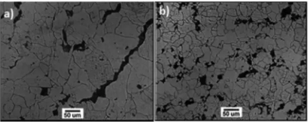
Figures 2a and 2b present the microstructures of microalloyed steels after annealing at 930 ºC with cooling in the furnace, in which a matrix of polygonal ferrite and islands of perlite compose the structures. In this paper the microstructural
classiication was made according to the deinition by Araki
Figures 3a and 3b present the microstructures of quenched and quenched plus tempering with cooling in air
of microalloyed steel containing 0.08% niobium. In the irst, acicular ferrite (AF), bainite (B) and martensite/austenite
(MA) white islands appear inner the grain from the rapid water cooling. In the second, it can be noted grain boundary allotriomorphic ferrite (GBA) plus bainite, represented by the sheaves of ferrite parallel with discontinuous carbides22.
The acicular constituents increase the yield and tensile strength of the material. The disposition of the ferrite plates
in diferent orientations is responsible for the diiculty of
crack propagation in the material23.
Despite Figure 4a does not show the MA phase, this constituent was also observed in lower amount in this steel. With relation to the tempering at 600 ºC in Figures 3b and 4b, MA phase disappears in both steels. Thus, there is an increasing elongation with yield strength and tensile strength reduction. In this condition, it is possible to form ferrite and cementite from retained austenite and martensite by a reconstructive mechanism, which may justify the decrease in hardness after this treatment as shown in Table 2. Moreover, accelerated cooling in the steels containing niobium and molybdenum, favor the formation of non-polygonal or acicular ferrite as well as bainite, which further contribute to strengthening9,22.
In both steels the microstructures indicate the presence of grain boundary allotriomorphic ferrite. The presence of thin layers of this constituent reduces the austenite grain surfaces, as potential nucleation sites for bainite, and favors the microstructural transformation from bainite to acicular ferrite24.
The amounts of the precipitates shown in Figures 5a and 5b were predicted by the FactSage software and the results are used just as indicators to the patterns in these steels. According to deviations from the equilibrium conditions, the FactSage can’t be employed for precipitates forming during the continuous cooling. These simulations are made considering the most thermodynamically probable products
and the values need to be conirmed by another technique,
such as transmission electronic microscopy (TEM).
Figure 2. The igures show the microstructures of the annealed
steels containing 0.01 (a) and 0.08 Nb (b). In the second, the grains are smaller because the higher niobium content (Nital 2% - COM).
Figure 3. 0.08 Nb steel: the irst shows the microstructure after
quenched at 900 ºC (Lepera - COM). The second shows the microstructure after quenched at 900 ºC and tempered at 600 ºC (Nital 2% - COM).
Figures 4a and 4b present the microstructures of quenched and quenched plus tempering with cooling in air
of microalloyed steel containing 0.01% niobium. In the irst,
after quenching, the microstructure is mostly composed of grain boundary alotriomorphic ferrite (GBA), Widmanstatten ferrite (WF), acicular ferrite (AF) and bainite (B)12,22. After
tempering in Figure 4b, it is possible to observe the acicular ferrite and bainite and in this case, the needles of ferrite grow
in diferent directions.
Figure 4. 0.01 Nb steel: the irst shows the microstructure after
quenched at 900 ºC (Nital 2% - COM). The second shows the microstructure after quenched at 900 ºC and tempered at 600 ºC (Nital 2% - MEV).
Figure 5. Thermodynamic simulation performed on 0.01 (a) and 0.08 (b) niobium steels.
It can be noted the presence of cementite, MC, M7C3 and M23C6 carbides, mainly of chrome and molybdenum, and at higher temperatures, niobium and titanium carbides
and nitrides and manganese sulide.
In microalloyed steels, niobium, vanadium and titanium, even with levels lower than 0.15%, promote the formation of
carbides inely dispersed in the matrix, during the austenite/
ferrite transformation25. As in the literature, simulation results
800 ºC. Moreover, literature results indicate that molybdenum
contents lower than 0.5 % is inefective in the secondary
hardening phenomena, it is possible that the relative higher amount of precipitation in 0.01 Nb steel, mainly Cr23C6 and Mo23C6, can justify the value shown in Figure 1a26.
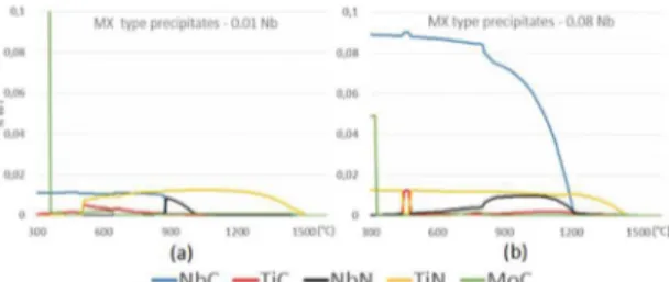
The thermodynamic simulations also indicate the probable precipitation of NbC for the 0.08 Nb steel at the
tempering temperature. Figures 6a and 6b show the MX type precipitation in both steels. It is known that MX type precipitates promotes a inely dispersed precipitation in the
matrix and contributes to wear resistance27.
Figure 6. MX type simulation on 0.01 (a) and 0.08 (b) niobium steels.
Regarding the wear resistance after quenching, steels with similar type of microstructure show a linear decrease in weight loss with decreasing grain size28. So, it is possible
that higher amount of niobium is responsible for grain
reining and the better wear performance in 0.08 Nb steel
after quenching.
With relation to yield and tensile strength, the microstructural analysis of other samples after quenching and quenching plus tempering conditions, reveals a higher amount of acicular ferrite and bainite in 0.01 Nb steel. According to the literature, this combination is the most indicated in the mechanical strength of microalloyed steels. It is possible that the higher molybdenum content is responsible for this result9,13.
4. Conclusions
The results of this research show that:
• The steels microstructures with acicular ferrite and bainite after quenching and tempering are suitable
to meet the values of standard API 5L-X70;
• According to the wear coeicients and simulation, the higher amount of niobium in 0.08 Nb steel
promotes grain reining which appears to lead to a
better wear performance after quenching; • Regarding the microstructure, molybdenum can be
replaced by niobium, because identical microstructure can be obtained using adequate heat treatments; • Molybdenum is responsible for a greater amount
of acicular and bainite ferrite in 0.01 Nb steel; • Acicular ferrite associated with bainite is indicated
to a better performance in mechanical strength of microalloyed steels;
• It is possible control the heat treatment for achieving the suitable microstructure and mechanical properties of the microalloyed steels for use in petrochemical industry.
5. Acknowledgement
The authors thank Grupo Metal for the samples and
FAPES for the inancial support.
6. References
1. Gray MJ, Siciliano F. High Strength Microalloyed Linepipe: Half a Century of Evolution. In: Pipeline Technology Conference; 2009 Oct 12-14; Ostende, Belgium.
2. Kalwa C, Hillenbrand HG, Gräf M. High strength steel pipes
- new developments and applications. In: Proceedings of Onshore Pipeline Conference; 2002 Jun 10-11; Dallas, TX,
USA. Ratingen: EUROPIPE; 2002.
3. Godefroid LB, Cândido LC, Tofolo RVB, Barbosa LHS.
Microstructure and mechanical properties of two API steels for iron ore pipelines. Materials Research. 2014;17(Suppl. 1):114-120.
4. Hillenbrand HG, Kalwa C. High strength line pipe for project
cost reduction. World Pipelines. 2002;2(1):1-10.
5. Hulka K. Sour Gas Resistant Steel. Niobium Information. 2001;18(1).
6. Li L, Xu L. Designing with High-Strength Low-Alloy Steels. In: Totten GE, Xie L, Funatani K, eds. Handbook of Mechanical Alloy Design. New York: Marcel Dekker; 2004. p. 249-320.
7. Fatehi A, Calvo J, Elwazri AM, Yue S. Strengthening of HSLA steels by cool deformation. Materials Science and Engineering: A.
2010;527(16-17):4233-4240. DOI: 10.1016/j.msea.2010.03.036
8. Mohrbacher H. Synergies of Niobium and Boron Microalloying in Molybdenum Based Bainitic and Martensitic Steels. In: Mohrbacher H, ed. Fundamentals and Applications of Mo and Nb Alloying in High Performance Steels. Volume 1. Pittsburgh: CBMM, IMOA and TMS. 2014; p. 83-108.
9. Shang CJ, Miao CL, Subramanian, SV. Austenite Processing and Phase Transformation of Niobium and Molybdenum Alloyed High Performance Structural Steel. In: Mohrbacher H, ed. Fundamentals and Applications of Mo and Nb Alloying in High Performance Steels. Volume 1. Pittsburgh: CBMM, IMOA and TMS. 2014. p. 37-61.
10. Lee WB, Hong SG, Park CG, Park SH. Carbide precipitation and high-temperature strength of hot-rolled high-strength, low-alloy steels containing Nb and Mo. Metallurgical and Materials Transactions A. 2002;33:1689-1698.
11. Kuo K. Carbides in chromium, molybdenum and tungsten steels. Journal of the Iron and Steel Institute. 1953;173:363-375.
12. Xu P, Bai B, Yin F, Fang H, Nagai K. Microstructure control and wear resistance of grain boundary allotriomorphic ferrite/
13. Huang BM, Yang JR, Huang CY. The Synergistic Efect of
Niobium-Molybdenum Additions on the Microstructure of Low-Carbon Bainitic Steel. In: Mohrbacher H, ed. Fundamentals and Applications of Mo and Nb Alloying in High Performance Steels. Volume 2. Pittsburgh: CBMM, IMOA and TMS. 2015; p. 29-50.
14. Altuna MA, Iza-Mendia A, Gutierrez I. Precipitation of Nb in Ferrite After Austenite Conditioning. Part II: Strengthening Contribution in High-Strength Low-Alloy (HSLA) Steels.
Metallurgical and Materials Transactions A.
2012;43(12):4571-4586. DOI: 10.1007/s11661-012-1270-x
15. Fernandes FAP, Heck SC, Pereira RG, Lombardi Neto A, Totten GE, Casteletti LC. Wear of plasma nitrided and nitrocarburized AISI 316L austenitic stainless steel. JAMME. 2010;40(2):175-179.
16. Rutherford KL, Hutchings IM. Theory and Application of
a Micro-Scale Abrasive Wear Test. Journal of Testing and Evaluation. 1997;25(2):250-260. DOI: 10.1520/JTE11487J 17. Rutherford KL, Hutchings IM. A micro-abrasive wear test, with
particular application to coated systems. Surface and Coatings Technology. 1996;79(1-3):231-239.
18. Bale CW, Chartrand P, Degterov SA, Eriksson G, Hack K,
Ben Mahfoud R, et al. FactSage Thermochemical Software and Databases. Calphad. 2002;26(2):189-228.
19. American Petroleum Institute. Speciication for line pipe. ANSI/API Speciication 5L. Washington: American Petroleum Institute; 2008.
20. Araki T, Kozasu I, Tankechi H, Shibata K, Enomoto M, Tamehiro
H, eds. Atlas for Bainitic microstructures. Volume 1. Tokio: ISIJ; 1992.
21. Krauss G, Thompson SW. Ferritic Microstructures in Continously
Cooled Low and Ultralow-carbon Steels. ISIJ International. 1995;35(8):937-945.
22. Bhadeshia HKDH. Bainite in Steels. 2nd ed. London: Institute
of Materials; 2001.
23. Lee CH, Bhadeshia HKDH, Lee HC. Efect of plastic deformation
on the formation of acicular ferrite. Materials Science and Engineering: A. 2003;360(1-2):249-257.
24. Babu SS, Bhadeshia HKDH. A direct study of grain boundary
allotriomorphic ferrite crystallography. Materials Science and Engineering: A. 1991;142(2):209-219.
25. Itman Filho A, Cardoso KR, Kestenbach HY. Quantitative
study of carbonitride precipitation in niobium and titanium microalloyed hot strip steel. Materials Science and Technology. 1997;13(1):49-55.
26. Honeycombe RWK, Bhadeshia HKDH. Steels: Microstructure and Properties. London: Elsevier; 2006. 360 p.
27. Porter DA, Easterling KE, Sherif M. Phase Transformations in Metals and Alloys. 3rd ed. London: CRC Press; 2009. 520 p.
28. Sundström A, Rendón J, Olsson M. Wear behaviour of some
low alloyed steels under combined impact/abrasion contact