Microstructural Transformation in a Root Pass of Superduplex Stainless Steel Multipass
Welding
Doris Ivette Villalobos-Veraa*, Ivan Mendoza-Bravoa
Received: July 6, 2016; Revised: October 31, 2016; Accepted: November 21, 2016
The microstructure of the root pass in a superduplex stainless steel multipass welding was investigated. Results showed that the welding metal has an austenite matrix with particles of sigma phase formed
in the ferrite/austenite interface and intragranularly.Eventhough the iller metal is intended to keep the
phase balance after welding,the welding metal presented a considerable decrease in the ferrite content and a high proportion of sigma phase. Despite the exposition to thermal cycles on every pass, the heat
afected zone presented a microstructure consisting of ferrite and austenite with a small proportion of
sigma phase.Therefore,the thermal cycles of every welding pass allowed the decomposition of ferrite
into austenite and sigma phase in points close to the heat source, changing the inal microstructure.
Keywords: duplex stainless steel, thermal cycles, sigma phase, multipass welding
* e-mail: [email protected]
1. Introduction
Superduplex stainless steels have been used in the chemical and petrochemical industries since they can be formed and welded with standard equipment and techniques1. However,
they are susceptible to the formation of secondary phases
like sigma(σ), chi(χ), γ2, M23C6 and Cr2N
2,3 when the material
is exposed to the temperature range of 300°C -1000°C4.
During a single pass welding, the material experience a
thermal cycle consisting of a very rapid heating to a peak
temperature and a fast cooling to room temperature. On the
other hand, in a multipass welding both the heat afected zone and the welding metal of the root pass are exposed to
the thermal cycles corresponding to the deposition of the subsequent passes. This cause a considerable reheating which can promote an unbalanced microstructure of ferrite and austenite because the temperature range for the formation of secondary phases through the decomposition of ferrite can be reached. For duplex alloys, the precipitation of sigma
phase takes place during cooling in the temperature range of
1200°C-800°C as well as the formation of austenite through the decomposition of ferrite to sigma phase and austenite. This means that the time in that temperature range is an important factor to consider in the welding of duplex alloys since sigma phase can precipitate from ferrite either in the
heat afected zone or the welding metal. Additionally, the
cooling rate plays an important role. A slow cooling rate of the weld promotes a favorable high austenite fraction, but can also give coarser grains and precipitation of brittle intermetallic phases such as sigma5. Sigma phase depends
on the temperature and time. Aging between 650°C and 950°C promotes the formation of sigma phase by eutectoid decomposition of ferrite or by nucleation and growth from
ferrite and austenite6,7. Solution annealed at 1080°C and
water quenched showed the presence of sigma phase in the ferrite/austenite interfaces8.
Therefore, the inal microstructure in the welding metal and the heat afected zone, are greatly dependent on the
heating and cooling rates9 and the peak temperature reached.
Eventhough multipass welding is more common during the practical industrial fabrication especially for the plate
or pipe of middle thickness10, investigations on the heat
afected zone and the welding metal of multipass welding is scarcely reported. This work, focused on the phase transformations in the heat afected zone and welding metal
of a superduplex stainles steel as a result of the thermal cycles in the root pass.
2. Experimental Procedure
UNS S32750 superduplex stainless steels plate with
dimension of 360 mm x 80 mm x 6 mm of thickness was
welded using GMAW process. Chemical composition of the
superduplex stainless steel and the iller metal is shown in
Table 1 and welding parameters in Table 2. These parameters were chosen based on trials performed on some superduplex
stainles steel plates in order to know the adecuate current,
voltage and welding speed for joining the plates.
The temperature distribution in the heat afected zone
corresponding to the root pass was calculated using a
heat-low equation for a thick plate model shown in equation (1)11
and the cooling time between 1200°C and 800°C (Δt12/8) was
calculated according to equation (2)5.
a Department of Mechanical Engineering, Instituto Tecnológico de Veracruz, Calz. Miguel Angel de
Quevedo, 2779, Veracruz, Veracruz, México
/
( )
Tp
To
e
r
q
2
1
2
o
r
t
where Tp is the peak temperature of the thermal cycle, T0is the initial temperature prior to welding, e is the base of natural logarithms, q is the heat input, v is the welding speed r is the distance from the fusion zone. For duplex
stainless steel, ρ is the speciic heat equal to 480 J/kg°C, ç is the density equal to 7800 kg/m3 and r is the distance
from the fusion zone. The thermal cycles were calculated
for point A, in the range of 7 mm to 10 mm from the fusion
zone as follows:
For r= 7 mm from the fusion zone:
( )
t
t
To
To
To
To
773
1
1073
1
1
1073
1
1
1473
1
2
/ /
12 8 8 5
D
=
D
-
-
--
-
-Tp-25°C= .2344 (4891.3)=1146°C+25°C=1177°C
The microstructural characterization was carried out by
standard techniques including grinding with SiC paper and polishing with 1, 3 and 9 microns diamond paste. To reveal the microstructure, the samples were etched with NaOH which
attacks ferrite, austenite and sigma phase12. The samples
were analyzed through optical microscopy. The percentage of phases was calculated using an image analyzer and the
microanalysis was performed by EDX.
3. Results and Discussion
The microstructure of the as-received condition in Figure 1
depicts a ≈54% ferrite and ≈46% austenite with grains oriented
to the rolling direction resulting in a balanced microstructure formed by islands of austenite in a ferrite matrix.
3.1 Welding Metal
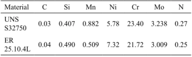
Two microstructures are observed in the welding metal corresponding to the root pass in Figure 2 since the phase balance of the superduplex stainless steel is disturbed when the material experiences high temperatures and fast
Table 1. Chemical composition of materials
Material C Si Mn Ni Cr Mo N
UNS
S32750 0.03 0.407 0.882 5.78 23.40 3.238 0.27
ER
25.10.4L 0.04 0.490 0.509 7.32 21.72 3.009 0.25
Table 2. Welding parameters Sample Protection
gas
Current
(A) Voltage (V) Welding speed
(mm/s)
S1 Ar 300 30 3
Figure 1. Microstructure of UNS S32750 superduplex stainless steel in the as-received condition.
or slow cooling rates such as in a multipass welding. The
irst microstructure in Figure 2a-2b, which is mostly present all over the welding metal, showed a signiicant decrease in the ferrite (≈15%) compared to the base material due to
the reheating promoted by the subsequent deposition of the
welding passes. The high proportion of austenite (≈73%)
is uniformely distributed and a substantial precipitation of
sigma phase particles (≈12%) is noticeable in the ferrite/
austenite interface and within the ferrite. In some areas there is evidence of the complete dissolution of the ferrite due to the formation of sigma.
The second microstructure in Figure 2c is located in some isolated areas in the welding metal, showing the formation of Widmanstätten austenite. Along with the ferrite and austenite, the presence of secondary austenite is evident as well as some particles of sigma phase in the ferrite/austenite interface and the growth of sigma phase
into the ferrite. The inal microstructure in the welding metal is heavily dependent on difusion12 and the chemical
composition of the iller metal plays an important role. Duplex alloys solidify as 100% ferrite approximately13 and
the welding metal of a single pass welding can consist in more ferrite than austenite. In order to restore the phase
balance, weld iller materials are usually overalloyed with 2-4% more Ni than in the base material14. During welding,
the disolution of austenite takes place during heating. At the end of solidiication and below the ferrite solvus, the
austenite begins to nucleate and grow along the ferrite grain boundaries and within the ferrite grains12.It can be assumed
that Ni promotes the austenite to nucleate at a temperature close to ferrite solvus in the ferrite grains boundaries and then intragranularly, resulting in a high proportion of austenite in the welding metal. Evenmore, it is considered that Ni
inluences the ferrite-austenite transformation since it can
increase the temperature of transformation during cooling15.
Figure 2. Microstructure of the welding metal corresponding to the root pass with the presence of austenite, ferrite and sigma phase.
Table 3. Chemical composition of ferrite, austenite and sigma phase in the welding metal
Phase Cr Fe Ni Mo Si
γ 18.1 64.2 7.2 2.39 0.69
δ 16.4 56.4 7.8 2.4 1.09
σ 23.2 47.9 5.4 7.4 1.18
Mo and Si when compared to the austenite and slightly richer compared to the ferrite. The hight amount of Cr and Mo of sigma phase, indicates that those elements are responsible for the formation of sigma since the rate of Cr and Mo
difusion in ferrite is almost 100 times greater than that in
austenite16.The proportion of sigma phase in the welding
metal can be related to the difussion of the ferrite-stabilizing
elements Cr and Mo17and the reheating experienced due to
the subsequent deposition of welding passes. The reheated welding metal in a multipass welding continually experience multiple exposures to the temperature range where sigma phase form. This results in the total dissolution of ferrite,
irst due to sigma precipitation occurs in the ferrite18,19
where the difussion of chromium and molybdenum takes
place from the ferrite to the ferrite/austenite interfaces20
and secondly, the nuclei of sigma phase then grow into the adjacent ferrite grains21. If the material keeps the ideal
condition of temperature and time, sigma phase will grow until the complete dissolution of ferrite.
3.2 Heat-Afected Zone
According to the heat distribution calculation in Figure
3, the peak temperature in the heat afected zone in point A
is 1177°C at 7 mm from the heat source and 904°C at 8 mm from the heat source. Beside this, the cooling time between
1200°C-800°C is ≈3 s. This means that the temperature where sigma phase forms is reached in the irst pass welding
and the time is enough to promote its formation. Since it
is a multipass welding, the heat afected zone experiences
reheating in the same points and a slow cooling rate. During
heating, the austenite to ferrite transformation takes place.
Then, the microstructure is fully ferritic having a grain growth
and inally, during cooling the austenite reforms and some
precipitation occurs12. Since there is no fusion involved, the
inal microstructure of ferrite and austenite is more balanced
compared to the welding metal.
Since the heat afected zone near the fusion zone is exposed to the thermal cycles of the root, iller and cover
passes, the resulting microstructure in Figure 4a shows the
presence of ferrite (≈40%±1.13), austenite (≈57%%±1.02) and small particles of sigma phase (≈1%%±.21) in the ferrite/
austenite interface as well as some islands of secondary
austenite (≈2%%±.37). On the other hand, the microstructure
in Figure 4b shows only ferrite, austenite and sigma phase. The temperature in the root pass due to the reheating allowed the formation of sigma phase through the difussion of Cr to the ferrite/austenite interfaces22 since they are high energy
zones which have been regarded as the favorable site for
the heterogeneous nucleation of sigma phase18. Additonally,
the cooling time plays an important role on the sigma phase formation. With rapid cooling, the ferrite/austenite reaction is suppressed23 and the amount of ferrite in the heat afected
Figure 3. Heat distribution in the root pass of the welding.
Figure 4. Microstructure of the heat afected zone corresponding to the root pass: a) austenite, ferrite, sigma phase and secondary austenite; b) austenite, ferrite and sigma phase.
cooling, the ferrite/austenite reaction takes place, allowing
the austenite to grow from ferrite but also the sigma phase can nucleate and grow from the ferrite. A slow cooling allows the difussion of Cr and Mo to the ferrite/austenite interfaces, promoting the formation of sigma phase isothermically. It has been reported that a multipass welding can cause
difusional transformation of ferrite to austenite in reheated
areas, as well as precipitation of intermetallic phases if the
temperature of the reheated zone is approximately 700–800°C5.
Chemical composition of phases in the heat afected zone
are presented in Table 4. Sigma phase is richer in Cr and Mo compared to the ferrite, indicating that those elements forming sigma come from the ferrite. On the other hand, it can be observed that the amount of Cr and Mo is bigger in the austenite compared to the ferrite probably due to the
permanence at high temperatures allowing the difusion of
Cr and Mo either to the austenite or sigma.
4. Conclusions
The results from this study suggest that the reheating in a multipass welding promote the formation of sigma
phase in the heat afected zone and the welding metal. Eventhough the chemical composition of both the iller
Table 4. Chemical composition of ferrite, austenite and sigma phase
in the heat afected zone
Phase Cr Fe Ni Mo Si
γ 21.83 58.21 8.28 3.03 0.44
δ 20.37 59.68 6.87 2.66 0.39
σ 22.56 58.06 8.55 3.27 0.73
metal and metal base is well balanced in order to promote the ferrite/austenite microstructure after welding, thermal
cycles can involve peak temperatures that fall in the
temperature range for sigma phase formation. It can be
assumed that the cooling time from the peak temperature
allow the ferrite to decompose through the difussion of Cr and Mo into the ferrite/austenite interfaces causing the formation of sigma phase and having enough time to grow into the center of the ferrite grain resulting in a complete dissolution of ferrite phase.
5. Acknowledgements
The author would like to acknowledge CONACYT for the
6. References
1. Cortie MB, Jackson EMLEM. Simulation of the precipitation
of sigma phase in duplex stainless steels. Metallurgical and Materials Transactions A. 1997;28(12):2477-2484.
2. Merino C, Hierro P, Fernandez P, Fosca C. Kinetic study of eutectoid transformation to 24% Cr/7% Ni duplex stainless steel.
In: Proceedings of the 4th International Conference on Duplex
Stainless Steels.Volume 1. Paper 41; 1994; Glasgow, Scotland.
3. Huang CS, Shih CC. Efects of nitrogen and high temperature aging on σ phase precipitation of duplex stainless steel. Materials Science and Engineering: A. 2005;402(1-2):66-75.
4. Sathirachinda N, Pettersson R, Wessman S, Kivisäkk U, Pan J. Scanning Kelvin probe force microscopy study of chromium
nitrides in 2507 super duplex stainless Steel--Implications and limitations. Electrochimica Acta. 2011;56(4):1792-1798.
5. Sieurin H, Sandström R. Austenite reformation in the heat-afected zone of duplex stainless steel 2205. Materials Science and Engineering: A. 2006;418(1-2):250-256.
6. Magnabosco R, Alonso-Falleiros N. Pit morphology and its relation to microstructure of 850ºC aged duplex stainless steel.
Corrosion. 2005;61(2):130-136.
7. Sieurin H, Sandström R. Sigma phase precipitation in duplex stainless steel 2205. Materials Science and Engineering: A.
2007;444(1-2):271-276.
8. Martins M, Casteletti LC. Sigma phase morphologies in cast and aged super duplex stainless steel. Materials Characterization.
2009;60(8):792-795.
9. Poorhaydari K, Patchett BM, Ivey DG. Estimation of cooling rate in the welding of plates with intermediate thickness. Welding Journal. 2005;84(10):149s-155s.
10. Tan H, Wang Z, Jiang Y, Yang Y, Deng B, Song H, Li J. Inluence
of welding thermal cycles on microstructure and pitting corrosion resistance of 2304 duplex stainless steels. Corrosion Science. 2012;55:368-377.
11. Easterling K. Introduction to the Physical Metallurgy of Welding. 2nd ed. Oxford: Butterworth-Heinemann; 1992.
12. Lippold JC, Kotecki DJ. Welding Metallurgy and Weldability of Stainless Steels. Hoboken: Wiley; 2005. 376 p.
13. Stevens KJ. Fatigue performance and microanalysis of heat
treated 2205 duplex stainless steel. Materials Science and Technology. 1999;15(8):903-908.
14. Muthupandi V, Bala Srinivasan P, Seshadri SK, Sundaresan S. Efect of weld metal chemistry and heat input on the structure
and properties of duplex stainless steel welds. Materials Science and Engineering: A. 2003;358(1-2):9-16.
15. Davis JR. ASM Specialty Handbook. Stainless Steels. Materials
Park: ASM International; 1994.
16. Padilha AF, Rios PR. Decomposition of Austenite in Austenitic Stainless Steels. ISIJ International. 2002;42(4):325-337.
17. Nishimoto K, Saida K, Katsuyama O. Prediction of Sigma
Phase Precipitation in Super Duplex Stainless Steel Weldments.
Welding in the World. 2006;50(3):13-28.
18. Chen TH, Yang JR. Efects of solution treatment and continuous cooling on σ-phase precipitation in a 2205 duplex stainless steel.
Materials Science and Engineering: A. 2001;311(1-2):28-41.
19. Duprez L, De Cooman BC, Akdut N. Redistribution of the substitutional elements Cr, Mo and Ni during σ and χ phase formation in a duplex
stainless steel. Steel Research International. 2001;72(8):311-316.
20. Solomon HD, Devine TM. Duplex stainless steels: a tale of
two phases. Metals Park: American Society for Metals; 1982. 21. Kuroda T, Nakade K, Ikeuchi K. Precipitation behavior of
sigma phase in duplex stainless steels and weld metals. Welding Reasearch Abroad.2001;47(2):2-7.
22. Magnabosco R. Kinetics of sigma phase formation in a Duplex
Stainless Steel. Materials Research. 2009;12(3):321-327.
23. Terasaki T, Gooch TG. Prediction of Cooling Time for