Microstructure characterization of a duplex
stainless steel weld by electron
backscattering diffraction and orientation
imaging microscopy techniques
Isabela Viegas Aguiar 1, Diana Pérez Escobar 1, Dagoberto Brandão Santos 1, Paulo J. Modenesi 1
1
Department of Metallurgical and Materials Engineering, Universidade Federal de Minas Gerais, Belo Horizonte, MG, Brazil, e-mail: [email protected], [email protected], [email protected],
ABSTRACT
This paper describes the electron backscatter diffraction (EBSD) technique used to characterize the microstructure (especially the morphology and constitution) of the base metal (BM), the heat-affected zone (HAZ) and the fusion zone (FZ) on a lean duplex stainless steel (LDX). This technique provides advantages due to its simplicity of use and greater depth of information, thereby increasing the amount of information obtained by traditional characterization techniques such as optical microscopy (OM), scanning electron microscopy (SEM), and transmission electron microscopy (TEM). The use of EBSD together with orientation imaging microscopy (OIM) as a tool to understand phase transformation paths and ferrite-austenite variant selection was discussed. Vickers microhardness measurements were performed and no significance difference between the different zones was found. Orientation distribution function (ODF) results show that there are no significant changes on the crystallographic texture of the samples after welding. The advantages of using SEM together with EBSD for microstructure analyzing and texture development were also discussed.
Key-words: Duplex stainless steel, welding, texture, EBSD, SEM
RESUMO
Este artigo descreve o uso da técnica de difração de elétrons retroespalhados (EBSD) para caracterizar a microestrutura (especialmente a sua morfologia e constituição) do metal base (MB), zona termicamente afetada (ZTA) e zona fundida (ZF) de um aço inoxidável “lean” duplex (AILD). Esta técnica fornece vantagens devido à sua simplicidade de uso e maior densidade de informação em comparação com a obtida por técnicas tradicionais de caracterização como as microscopias óptica (MO), eletrônica de varredura (MEV) e eletrônica de transmissão (MET). O uso de EBSD juntamente com microscopia de orientação de imagem (OIM) para compreender as diferentes transformações de fase ferrita-austenita é discutido. Medidas de microdureza Vickers foram feitas e não foi achada nenhuma diferença significativa entre as diferentes zonas. A função distribuição de orientação dos grãos (FDO) mostrou que na há mudanças significativas na textura cristalográfica nas amostras após a solda. As vantagens do uso de microscopia eletrônica de varredura juntamente com EBSD para analisar a microestrutura e o desenvolvimento da textura são também discutidas.
Palavras-Chave: Aço inoxidável duplex, soldagem, textura, EBSD, MEV
1.INTRODUCTION
This microstructure can be considered intermediary between austenitic and ferritic stainless steels. Duplex stainless steels have higher strength than austenitic stainless steels, higher toughness than ferritic stainless steels and good weldability [1-4]. Furthermore, due to the high Cr content and the presence of alloying elements in the material, the duplex stainless steels present superior corrosion resistance in different environments when compared to other types of similar stainless steels, together with a yield point that is superior to the one of austenitic stainless steels. This behavior allows thickness and weight reduction of a component or equipment produced with this type of steel [5-6].
Due to their reduced amount of Ni, the production cost of duplex stainless steels is cheaper than austenitic
stainless steels, particularly on some steels which are called “lean duplex stainless steels” (LDX) where the amount of Mo and Ni is reduced even more [5-7].
LDX steels are used for different applications: as storage tanks in the paper and cellulose industry, in the fabrication of bridges, water treatment stations, mining, ethanol production plants, food storage tanks and for construction of airport ceilings, among others [7]. In most of these applications welding is used to join the parts, being then a crucial process in the fabrication involving LDX steels [7]. Among these steels, the most common one is the UNS S32304, table 1 [7,8]
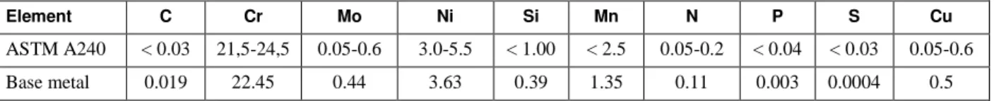
Table 1: Chemical composition (%weight) of the UNS S32304 steel.
Element C Cr Mo Ni Si Mn N P S Cu
ASTM A240 < 0.03 21,5-24,5 0.05-0.6 3.0-5.5 < 1.00 < 2.5 0.05-0.2 < 0.04 < 0.03 0.05-0.6
Base metal 0.019 22.45 0.44 3.63 0.39 1.35 0.11 0.003 0.0004 0.5
Changes in microstructure of duplex stainless steels during fabrication depends on the characteristics of the processing used (welding, cold working, heat treatments, etc.) and their variations and may have a significant impact on the final microstructure. Hence, the knowledge of these changes is extremely important to guarantee the high quality of the products obtained with these steels, especially after heat treatment and welding [2-5,9,10].
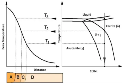
Figure 1: Schematic representation of the weld constitution of a duplex stainless steels. Left: vertical section of the Fe-Cr-Ni system for around 70% Fe. A – MZ, B – high temperature HAZ, C – low temperature HAZ and D – BM [1].
At regions that were heated to temperatures lower than 1000 °C, particularly those that are submitted to multiple thermal cycles (multipass welding), the contents of Cr and Mo of the of the higher alloyed duplex stainless steels can lead to the formation of different intermetallic compounds, especially the so-called sigma () and chi () phases. This precipitation can cause a reduction of the toughness and corrosion resistance of the material [4-6,12]. Due to the lower amount of alloying elements, particularly Mo, the formation of intermetallic compound tend to be a less common problem during the welding of LDX steels. Exposition of the MZ and high temperature HAZ to temperatures between 700 and 1000 °C during subsequent thermal cycles also contributes to the formation of secondary austenite in these regions. This austenite forms as extensions of previous austenite plates or as new formed grains, largely intragranularly. Primary and secondary austenite regions tend to present different chemical compositions [23].
As previously discussed, the duplex stainless steels present typically two phases: ferrite and austenite. The amount and morphology of the ferrite affect the properties of the weld joints as cracking susceptibility, corrosion resistance and low temperature fracture toughness. Furthermore, it was suggested that some of these properties are related to the crystallographic relationship between and [14-16].
Duplex stainless steels are still not widely used in Brazil, but there is an increasing demand caused by the development of offshore oil exploration. This is particularly for LDX steels, which combine a lower cost, due to the reduced amount of Ni and Mo, with a corrosion resistance similar or superior than that of common austenite steels. LDX steels have a significant potential of being used in different applications related to the oil business and other industries.
According to Badji et al. [15], limited information is available in the literature on the link between texture, microstructure and anisotropic properties of duplex stainless steel after arc welding. Understanding the development of crystallographic textures and microstructures in these welds can be very useful to control their final properties especially when, for instance, a post-weld annealing treatment is to be carried on. In this direction, the focus here will be on the combined use of traditional techniques together with more recent and advanced ones capable of yielding greater depth of information, thereby supplementing the information obtained by traditional characterization techniques such as scanning electron microscopy and transmission electron microscopy [17]. The use of electron backscattered diffraction with orientation imaging microscopy as a tool to understand phase transformation paths from and between ferrite and austenite was discussed.
2. MATERIALS AND METHODS
The material used in the present work is a LDX UNS S32304 steel plate with nominal thickness of 22 mm, provided by a national of stainless steels producer. Its chemical composition is presented on Table 1.
Two autogenenous TIG bead-on-plate passes were performed on two 22 x 30 x 75 mm specimens. The second pass presented a superposition of approximately 50% over the first one, Figure 2 [7]. Mechanized welding was done with a torch angle of 10o opposite to the weld direction, an arc length was 3.5 mm (resulting on a welding voltage of approximately 16 V), a current of 190 A, and a weld speed of 12.5 and 9.2 cm.min-1 for each
specimen (A and B). Interpass temperature was kept below 100°C.
After welding, cross section samples of each specimen were cut for macro and microscopic analysis. The samples were ground and then polished manually down to 1 m diamond paste. The samples were then etched with Marble, Kallings and Behara etchants. During macroscopic analysis, the dimensions of the weld bead were measured using the Image J software. For microstructural analysis, the regions shown in Figure 2 were considered.
For EBSD measurements, the samples were further polished automatically for 90 min in colloidal silicon of 0.04 µm. Analysis was done in a scanning electron microscope with tungsten (W) filament, 20kV acceleration potential and step sizes of 0.5 or 3 µm.
Figure 2: Schematic representation of the welds and studied zones: FZ1 – Unaltered first pass FZ, FZ2 – Second pass FZ, HAZ1 – Unaltered first pass HAZ, HAZ2 – Second pass HAZ (in the base metal), FHAZ – Second pass HAZ (in FZ1), HAZ1-2 – HAZ1 altered by the second pass.
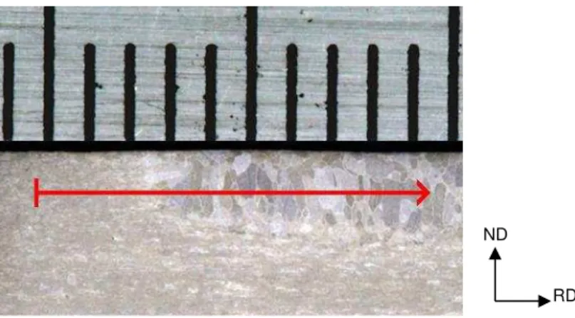
Vickers microhardness was performed for both welds using 300 gf of load. Measurements started in the base metal and finished at the fusion zone along a line 1 mm below the specimen surface, Figure 3. Twenty hardness measurements, separated by 250 m, were done on each specimen.
Figure 3: Measuring arrangement of the microhardness on specimen B.
3. RESULTS
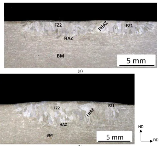
Figure 4 shows the macroscopic aspect of samples A and B etched with Marble. The second pass is on the left side of both images.
(a)
(b)
Figure 4: Macrographs of (a) specimen B (welding speed of 12.5 cmmin-1). (b) Specimen A (welding speed of 9.2 cm.min-1). Etched with Marble etchant.
Weld B was performed with higher welding energy (20 kJ/cm) than weld A (15 kJ/cm), and, as expected, has bigger dimensions. Maximum weld penetrations were 2.6 and 2.0 mm respectively and cross section fused areas (FZ2, Figure 4) were 29.9 and 18.8 mm2.
3.1 Optical Microscopy and SEM results
The best images for optical microscopy were obtained using Behara etchant which colorizes the structure. For scanning electron microscopy, the best results were obtained when the Marble and Kallings etchants were used. Both highlighted well the microstructure of the base metal, HAZ and fusion zone.
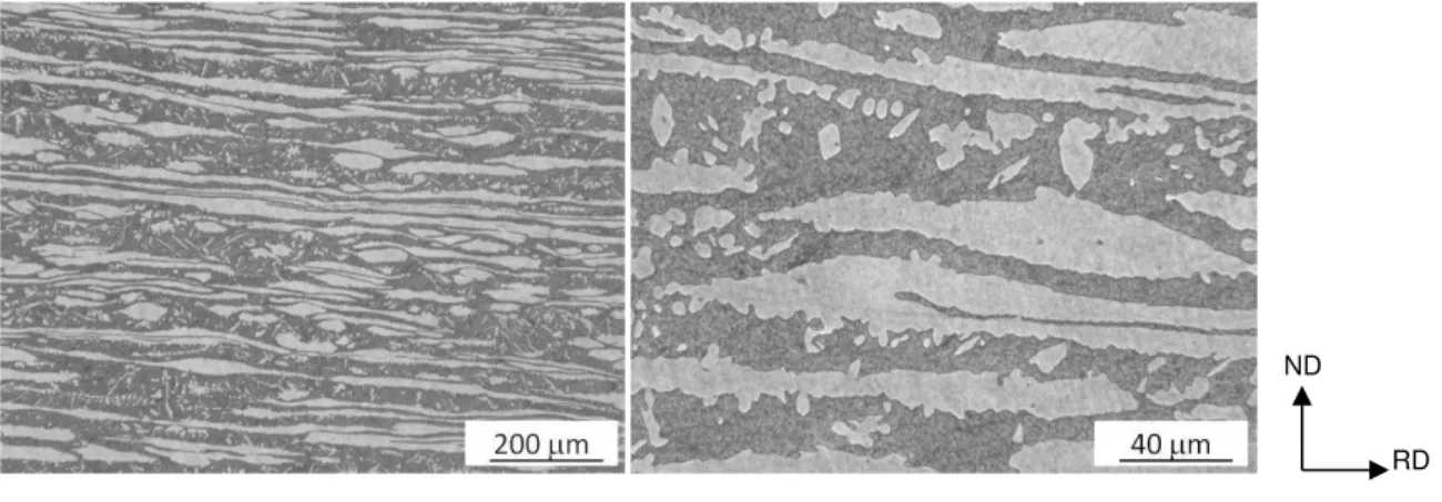
The base metal (Figure 5) presents a volume fraction of austenite, measured by image analysis in the optical microscope, was of 46% (54% ferrite). The austenite (light regions) and ferrite (dark regions) grains are elongated and have a grain size between 10 and 40 µm, Figures 5 and 6.
(a) (b)
Figure 5: Optical metallography of the base metal: austenite (light) and ferrite (dark). (a) Kallings etchant and (b) Marble etchant.
(a) (b)
Figure 6: SEM metallography of the base metal. (a) and (b) samples were etched with Marble etchant. (c) higher magnification and etched with Kalling etchant.
Most of the base metal austenite has polygonal shape (Figure 5 and 6(b)), but Widmanstätten austenite plates are sometimes observed, Figure 6(a). According to MONLEVADE, et al. [[18]], the orientation relationships between intragranular acicular austenite and ferrite are close to K-S with small deviation (around 3°). These deviations are, probable, a compromise in order to maintain the atomic arrangement in the interface limits and to keep the invariant line during phase transformation.
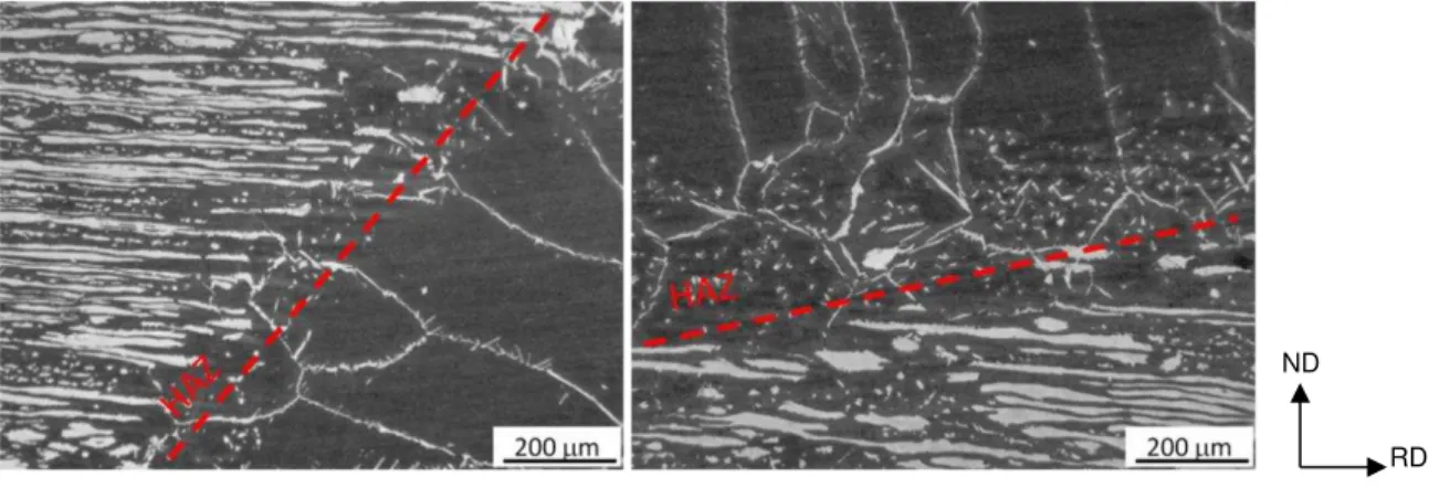
The coarse microstructures of the columnar grains present on the weld zone (FZ) are shown in Figures 7 to 10. The HAZ on specimen B is very thin, with an austenite fraction of ~30%, as shown in Figure 7. It is possible to observe from figures 8(a) and 9(a) the dimensions of the ferrite grain at the FZ, which values higher than 0.5 mm and with some of them reaching diameters of 1 mm. In turn, the length of the HAZ varies between 200 and 500 m as shown in Figures 7 and 8.
RD ND
(a) (b)
Figure 7: Optical metallography of the HAZ and fusion zone for the specimen B: austenite (light) and ferrite(dark). Etched with Behara etchant.
(a) (b)
Figure 8: SEM metallography with different magnifications of the base metal, HAZ and FZ zones with the HAZ zone shown in the middle of the image for (a) specimen A and (b) specimen B. Etched with Marble etchant.
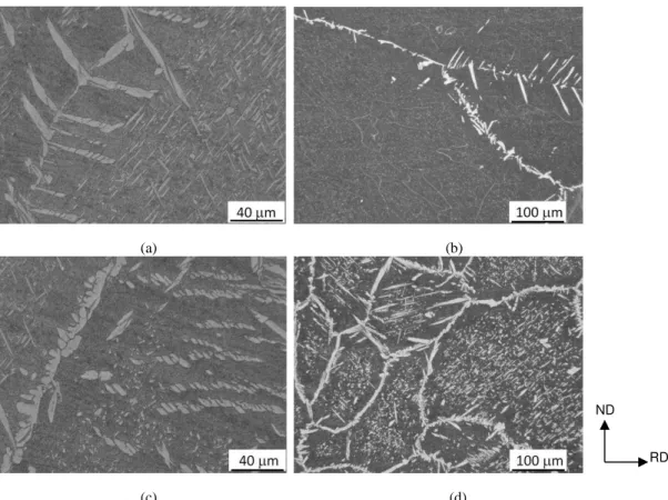
Figure 9(a) illustrates the austenite that precipitated on the weld metal of both samples. Most austenite is formed mainly by intergranular allotriomorphic grains with polygonal morphology. The fraction of austenite in the welds is around 10 to 16 % and the length of the columnar grains is between 100 and 200 m, Figure 10(c). This small amount of austenite is expected because no filler metal was used in the tests.
On the other hand, the austenite fraction increases to 50% in the region that was reheated by the second weld pass, as presented in figure 9(c,d). At both HAZ1-2 and FHAZ, Figures 9(d) and 10(b,d), there is an intense intragranular austenite precipitation in ferrite caused by heating at intermediary temperatures during the second thermal cycle. These precipitates also have Widmansttäten morphology, and are known as secondary austenite in literature [15,16]. This type of austenite can nucleate intragranularly, directly at the ferrite grain boundary (Fig. 9(b) and Fig. 10(a)) or from the allotriomorphic austenite formed at the ferrite grain boundary.
RD ND
(a) (b)
(c) (d)
Figure 9: Optical metallography of the FZ for the A (a),(c) and B (b),(d) specimens. Etched with Behara etchant.
(a) (b)
(c) (d)
Figure 10: SEM metallography of the FZ for the A (a),(b) A and B (c),(d) specimens. Etched with Kallings etchant. RD ND
No evidence of precipitation of intermetallic phases or carbides was found on the weld metal. The same occurred at the reheated areas and at the HAZ for the studied specimens, even though this phenomenon has been frequently reported in literature for more alloyed duplex stainless steels [10,11,12].
The chemical analysis of the two welds, performed by electron probe microanalysis, is presented in Table 2. As it was expected, due to the fact that the weld are autogenous, no significance difference was found between them.
Table 2: Chemical composition of specimens A and B obtained by EDS (%weight)
ELEMENT (% WEIGHT)
SPECIMEN
A B
Si 0.9 1.1
Mo 1.1 1.3
Cr 23.1 22.9
Mn 1.9 1.3
Fe 68.9 69.7
Ni 3.9 3.7
3.2 Vickers microhardness results
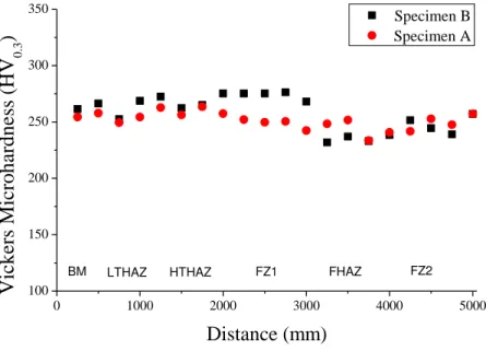
The values obtained for microhardness for both A and B welds are presented in Figure 11. These results ranged from 231 to 277 HV and do not reveal any zone with excessive hardness (> 300 HV). They are also in accordance with the ones found in literature [6,7,10] and do not indicate the formation of appreciable amounts of hard phases in both weld beads and their heat affected zones.
0 1000 2000 3000 4000 5000
100 150 200 250 300 350 Specimen B Specimen A
Vick
ers M
ic
roh
ard
n
ess
(HV
0 .3)
Distance (mm)
BM LTHAZ HTHAZ FZ1 FHAZ FZ2
Figure 11: Vickers microhardness of the A and B welds.
Table 3: Microhardness Vickers (300 gf) of the base metal, HAZ, and weld
SPECIMEN BM HAZ WELD
A 256 2 257 5 246 6
3.3 EBSD results
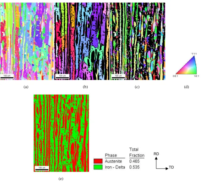
Figures 12(a-e) presents the IPF, ferrite grain distribution, austenite grain distribution and the phase distribution of the base metal microstructure obtained by EBSD.
(a) (b) (c) (d)
(e)
Figure 12: (a) Inverse pole figure (IPF) of the base metal, (b) ferrite grains distribution, (c) austenite grains distribution, (d) reference triangle, (e) quantitative distribution of austenite and ferrite.
From Figure 12(e) it was possible to obtain the quantitative distribution of the phases and it was found that the base metal originally contains 46% of austenite and 54% of ferrite. These results are in agreement with the ones found by optical microscopy.
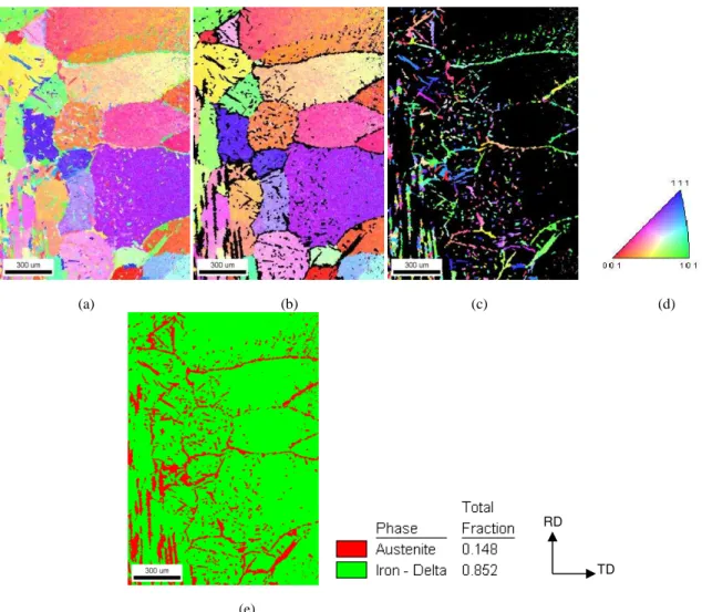
Figures 13 presents 14 the IPF, ferrite grain distribution, austenite grain distribution and the phase distribution of the HAZ, the weld zone and part of the base metal microstructure of the specimen A and B respectively, all obtained by EBSD measurements.
(a) (b) (c) (d)
(e)
Figure 13: (a) Inverse pole figure (IPF) of the weld A, (b) ferrite grains distribution, (c) austenite grains distribution, (d) reference triangle, (e) quantitative distribution of austenite and ferrite.
(e)
Figure 14: (a) Inverse pole figure (IPF) of the weld B, (b) ferrite grains distribution, (c) austenite grains distribution, (d) reference triangle, (e) quantitative distribution of austenite and ferrite.
It is possible to observe from the results that the amount of austenite volume fraction on the specimen A is higher than on the specimen B.
Figure 15 illustrates the principals fiber and components textures orientations in the Euler space (2 = 45º)
[15].
Figure 15: Fiber and components textures orientations in the Euler space (2 = 45º) [15].
Figure 16 presents the textures for the austenite and ferrite of the base metal, specimen A and specimen B.
Figure 16: Texture results for the austenite and ferrite of the base metal, specimen A and specimen B.
4. DISCUSSION
The difference on the amount of austenite and ferrite through the weld structure occurs because of the differences on cooling rates, amount of nitrogen and peak temperatures. It is possible to observe that in the central zone of the weld (FHAZ), where the cooling takes more time (compared to HAZ1 and HAZ2) there is an increase on the amount of austenite and that at the HAZ1-2 there is an increase on ferrite. This will eventually favor the precipitation of the phase in subsequent heating, as it occurs, for example, in multi passes welding [15]. The HAZ presented two regions: one of high temperature, which has small and dispersed austenite grains and a second low temperature region with the remained austenite from the base metal. Both regions presented secondary austenite at the interior of the ferrite grains; however, this austenite was also found in higher amounts at the FHAZ, where subsequent passes occurred. Widmanstätten austenite was found at the FZ, and it was also possible to observe secondary austenite, especially at FHAZ in higher amounts than at HAZ. It was also evident that the secondary austenite precipitates at the interior of the ferrite grains for the HAZ1-2 and FZ zones, but in lower amount at the FZ, where it was observed a solidification substructure, as subgrains, which probably contain nitrites at the their boundaries.
Texture results for the base metal, show that the predominant texture component on the austenite phase is Brass (B:{011}ۃ112ۄ) although there is also a significant amount of the Copper (Cu:{112}ۃ111ۄ) and, in less intensity, the Goss component (G:{110}ۃ001ۄ) in the same region as the Brass. On the other hand, the δ-ferrite texture reveals a strong presence of the α-fiber (<110>//RD) and a weak - fiber ({111}<011>~{111}<112>). These results are similar to the ones found in literature [15,19,20].
Texture at the HAZ of sample A reveals that the predominant component on the austenite phase is steel Brass, but dislocated towards the Goss component. The Copper component is still present but in less intensity. The δ-ferrite texture suffers alteration of the -fiber changing to a week rotated cube component and there is an appearance of the Goss component, also in less intensity.
5. CONCLUSIONS
A LDX duplex stainless steel was submitted to two consecutive passes with a superposition of approximately 50% with two different weld speeds using the mechanized TIG methodology.
It was found that the amount of austenite decreases at the HAZ after welding. This small amount of austenite was expected because no weld metal was used in the tests. On the other hand, the austenite volume fraction increases to 50% in the region that was reheated (FHAZ), which was explained by the slow cooling at this zone. The HAZ presented two regions: one of high temperature, which has small and dispersed austenite grains and a second low temperature region with the remained austenite from the base metal. Both regions presented secondary austenite at the interior of the ferritic grains.
Evidence of precipitation of intermetallic phases or carbides was not found on the weld metal. The same occurred at the reheated areas and at the HAZ for the studied specimens.
The values obtained for microhardness of the A and B weld did not revealed zones with excessive hardness (> 300 HV). These values are in accordance with the ones found in literature and therefore there was no indication of changes after the second pass.
Texture measurements revealed small changes on the Copper component for the austenite on both samples when compared to the base metal. For the ferrite phase, it was found that the -fiber changes to a weak rotated cube component and there is an appearance of the Goss{110}<001> component for the specimen A and that it presents the rotated cube component {001}<011>, for the specimen B.
The use of the EBSD technique for crystallographic analysis as was developed in this work enhances the information that can be obtained from the collected data and can also provide new perspectives on welding procedures, steel composition, constituents distribution, grain size and phase transformation of duplex steels as well as for other alloys. It also presents advantages when compared to the XRD (X-Ray diffraction) technique because in addition to quantifying the phases, it can provide information about the morphology and precipitation location of the phases.
6. ACKNOWLEDGMENTS
The authors would like to thank Ms. Ronaldo Cardoso Jr. from ESAB and Prof. Alexandre Q. Bracarense from the Department of Mechanical Engineering (UFMG) for providing the samples and to the CNPq and CAPES institutions for granting academic scholarships to the authors.
7. BIBLIOGRAPHY
[1] MODENESI, P.J., Soldabilidade dos Aços Inoxidáveis, Coleção Tecnologia da Soldagem, Osasco-SP, 2001, p.13.
[2] LO, K.H., SHEK, C.H., J.K., L.A.I., “Recent developments in stainless steels”. Materials Science and Engineering v. 65, n.4-6, pp. 39-104, May 2009.
[3] LAD, T., NORTH, T. H., “Fusion Welding of Stainless Steels”, Canadian Metallurgical Quarterly, v.27, n.1, pp. 65-77, Jan 1988.
[4] BROOKS, J.A., THOMPSON, A.W., “Microstructural development and solidification cracking susceptibility of austenitic stainless steel welds”, In: International Materials Review, v. 36, n.1 pp. 16-44, 1991.
[5] McPHEARSON, N.A., LI, Y., BAKER, T.N., “Microstructure and properties of as welded duplex stainless steel”, Science and Technology of Welding, v.5, n. 4, pp. 235-244, Aug. 2010.
[6] SAITHALA, J.R., MAHAJANAM, S., UBHI, H.S., “Effect of Sigma Phase on the Environmental Assisted Cracking of Super Duplex Stainless Steel in Oil Field Environments”. In: Proceedings of the NACE International Corrosion Conference and Expo, pp. 1-12, Houston, 2012.
[7] CARDOSO JÚNIOR, R. Avaliação da Soldagem Multipasse de Chapas Espessas do Aço Inoxidável Lean Duplex UNS S32304 Soldadas pelos Processos SMAW, GMAW e F CAW, Tese de Mestrado, PPGMEC/UFMG, Belo Horizonte, MG, Brasil, 2012.
[9] SIEURIN, H., SANDSTRÖM, R., “Austenite reformation in the heat-affected zone of duplex stainless steel 2205”. Materials Science and Engineering A, v.418A, n.1-2, pp. 250-256, Feb. 2006.
[10] MUTHUPANDI, V., SRINIVASAN, P.B., SESHADRI, S.K., et al., “Effect of weld metal chemistry and heat input on the structure and properties of duplex stainless steel welds”, Materials Science and Engineering A, v.358A, n.1-2, pp. 9-16, Oct 2003.
[11] KOUSSY, M.R El., MAHALLAWI, I.S. El, KHALIFA, W., et al., “Effects of thermal aging on microstructure and mechanical properties of duplex stainless steel weldments”, Materials Science and Technology, v.20, n.3, pp. 375-381, Mar 2004.
[12] DING, L.Z., WANG, H., MENG, Q.S., “Influence of precipitation phase of Cr2N on comprehensive
performances of weld joints for S32101 duplex stainless steels”, Materials Research Innovations, v.17, n.1, pp. 1215-1219, Jul. 2013.
[13] DOBRANSZKY, J., SZABO, P.J., BERECZ, T., et al., “Energy-dispersive spectroscopy and electron backscatter diffraction analysis of isothermally aged SAF 2205 type superduplex stainless steel”, Spectrochimica Acta Part B, v. 59, pp. 1781–1788, Sep 2004.
[14] FUKUMOTO, S., OKANE, T., UMEDA, T., et al., “Crystallographic Relationships between -Ferrite and -Austenite during Unidirectional Solidification of Fe–Cr–Ni Alloys”, ISIJ International, v.40, n.7, pp. 677-684, May 2000
[15] BADJI, R., BACROIX, B., BOUABDALLAH, M., “Texture, microstructure and anisotropic properties in annealed 2205 duplex stainless steel welds”, Materials Characterization, v.62, pp. 833-843, Jun 2011. [16] MENEZES, J.W.A., ABREU, H., KUNDU, S., et al., “Crystallography of Widmanstätten austenite in
duplex stainless steel weld metal”, Science and Technology of Welding and Joining, v.14, n.1, pp. 4-10, 2009.
[17] NARAYANAN, B.K.., KOVARIK, L., QUINTANA, M.A., et al., “Characterization of ferritic weld microstructures using various electron microscopy techniques: a review”, Science and Technology of Welding and Joining, v.16, n.1, pp. 12-22, 2011.
[18] MONLEVADE, E.F., GOLDENSTEIN, H., SANDOVAL, I.G.F., “Intragranular formation of austenite during delta ferrite decomposition in a duplex stainless steel”, Journal of Materials Science, v.45, pp. 5089– 5093, Apr. 2010.
[19] HAMADA, J-I., ONO, N., “Effect of Microstructure before Cold Rolling on Texture and Formability of Duplex Stainless Steel Sheet”, Materials Transactions, v.51, pp. 635-643, 2010.
[20] BRACKE, L., VERBEKEN, K., KESTENS, L., “Texture generation and implications in TWIP steels”, Scripta Materialia, v. 66, pp. 1007-1011, 2012.
[21] TOTH, L.S., JONAS, J.J., DANIEL, D., et al., “Development of Ferrite Rolling Textures in Low- and Extra Low-Carbon Steels”, Metallurgical Transactions A, v.21A, pp. 2985-3000, 1990.
[22] JONAS, J.J. “Effect of Austenite Recrystallization on Toughness of Pipeline Steels”, Materials Science Forum, v.753, pp. 546-553, 2013.