Abstract
This research was an experimental and numerical investigation of the cylindrical expanded Sheets under impact loading. Two types of absorbers with different cell angles were examined (i.e. =0 and =90). The experiments were performed using the drop hammer setup, and the numerical simulations were conducted by ABAQUS. In this study, the type of collapse, force-displacement diagrams, the crushing length, and the absorbed energy were investigated. The experimental and numerical results were compared, and it was ob-served that they were in good agreement. Results showed that the
absorbers with the cell angle of α=0 had a symmetric collapse and
a high energy absorption capacity. Also, various heights of fall were considered for the impact mass to examine the type of collapse in the models. The crushing amounts of the models were also compared in different heights. Multi-walled expanded metal tubes were stud-ied, and the effect of being multi-walled in collapse was examined.
Keywords
Expanded metal energy absorbers; energy absorption capacity; dy-namic axial loading; effect of impact force; finite element.
Experimental and numerical investigation of lattice-walled
cylindrical shell under low axial impact velocities
Nomenclature
A the cross section and yield stress at Eq.7 B strain-hardening factor
C the coefficient of strain rate sensitivity 0
c the stress wave propagation velocity D the model diameter
E the elasticity modulus a
E the energy absorption capacity EMT the model label
L the length of model 1
l the greater length of cells diameter
H. Hatamia*
M. Damghani Nourib
aPh.D. of Semnan university, Semnan, Iran
bAssociate Professor of Semnan univer-sity, Semnan, Iran
Corresponding author: a*[email protected]
http://dx.doi.org/10.1590/1679-78251919
2
l the lesser length of cells diameter
m the impact mass , the thermal coefficient related to softening in Eq.7 n the strain-hardening coefficient
N_C the number of circular cells N_L the number of longitudinal cells
m
P the mean force peak
P The initial peak force
SEAa the energy absorbed per unit weight t the thikness of cells
T the temperature before dynamic loading T the homologous temperature
melt
T the melting temperature v the impact velocity w the width of cells
m
W the weight of tube x length of crushing
angle of the greater diameter of cell to the horizontal axis shape factor
the crushing length s
stress
t the transmitted stress wave
R t
the reflected stress wave s
strain s
strain rate
1 INTRODUCTION
Energy absorption systems are used in many engineering applications, moving systems in particular, for preventing or reducing damage. Thin-walled structures are high strength-to-weight ratios and high energy absorption capacity. For this reason, they are the center of attention in many different indus-tries including car manufacturing indusindus-tries. In some systems, energy absorbers are used for absorbing kinetic energy or converting it into other forms of energy. Mechanical cylindrical tubes absorb energy through doing work in the plastic region. The most common absorbers are thin-walled cylindrical shells which dissipate energy by collapsing under axial loads. These absorbers are irreversible and cannot be reused upon deformation (Lau et al., 2012).
Most absorbers are of the throw-away type and are discarded upon plastic deformation. For this reason, design requirements for such tubes would be achieving higher absorbing capability at lower mass with emphasis on higher specific energy absorption. Axial collapse in different designs usually occurs in three stages. First, the collapse force reaches a peak value to overcome the initial tube resistance. Second, the force diminishes and fluctuates as crushing develops. Third, the force rapidly increases, expanding the collapsed parts until the collapse ends (Ghamarian et al., 2011; Song et al., 2013).
Generally, expanded metal tubes are used in the design industry and for security purposes. In recent years, expanded metal tubes have found prominent applications in the automobile industry. These structures are specifically used in sensitive structures, e.g., thin-walled structures. This property is used for plastic collapse. Thin-walled structures are not only good energy absorbers, but also rela-tively cheap and light in weight. The collapse mechanism in latticed tubes is as follows: first, the cells start closing as the load increases, and a plastic moment is applied about nodal intersections. These plastic deformations gradually spread. The failure mechanism specifically appears as plastic hinges at cell junctions. The force-displacement response curves show gradual increase in the force, which is a favorable behavior for an energy absorbing system since in these systems damping of the force must be gradual. By observing the failure mode of the expanded metal tube and its deformation configu-ration, we conclude that the deformation mechanism is layered (Graciano et al., 2009, 2012).
Alghamdi (2001) introduced research conducted during the past four decades on energy absorbers subjected to impact loading. Olabi et al. (2007) introduced second general review of metal tubes used as energy absorbers in axial collapse. Jones (2010b) compared various energy absorbing systems in terms of the effective factors on energy absorption. Upon studying the energy absorbing capacity of the tubes with various cross sections (circular, rectangular, hexagonal, triangular, pyramidal, and conical), Nia and Hamedani (2010) concluded that tubes with circular cross sections have the highest energy absorbing capacity.
Structural shape plays an important role in optimizing the factors that affect energy absorption. The important function to be considered when developing energy absorbing structures is to reduce the initial force peak in the force-displacement curve response. In applied energy absorber programs, the initial peak force must be reduced for stabilizing the structural response under quasi-static loading. The initial peak force in axial compression tests can be reduced via introducing some kind of defect such as grooves Zhang et al. (2007). Latticed energy absorbers can meet all the requirements for efficient energy absorption. Graciano et al. (2012) studied the axial collapse of circular tubes made of expanded metal sheets. Their test results showed that the collapse mechanism depended on cell di-rection, and that the initial peak force depended on the number of cross sectional cells (Graciano et al., 2012).
Impact tests and numerical analysis are concentrated on the failure mechanism as well as the load bearing capacity. On the average, impact loading is applied via free fall of a hammer. Due to the specific features of impact loading, the dynamic response of the structure under impact loading is evidently different from that under quasi-static loading. These results were recorded completely dur-ing testdur-ing (Qu et al., 2014).
Variations of the impacting mass affects only the structural deformation and has no considerable effect on energy-absorption productivity. If a thin-walled part collapses, variations in its thickness would directly affect the structure’s cross section. Impact loading increases the thickness of the struc-ture and reduces its deformation, but can fully absorb the impact energy. Thus, wall thickness has a considerable effect on energy absorption. Velocity variation of the impacting body would directly change the impact force and cause a change in the initial peak force and the mean force as well. Test results show that kinetic energy is affected more by the velocity of the impacting body than by its mass. This also affects the amount of the absorbed energy (Tai, 2010).
To better understand the behavior of thin-walled structures, these structures were investigated experimentally, analytically, and numerically. The experimental method is perhaps the most expen-sive method from the viewpoint of time and material selection, but is necessary for validating numer-ical methods. With due regard of the tests conducted on long and short aluminum tubes, their global and progressive buckling were studies. In short, metal energy absorbers fail under axial compressive loads in various modes including axial collapse, global buckling, or at a point depending on geometric parameters (length and cross sectional area) (Martínez et al., 2013). Gupta and Venkatesh (2006) also conducted experimental and numerical studies on cylindrical aluminum sheets with different lengths and diameters. Advances in computational power in the past two decades have prompted researchers to turn to numerical methods for analyzing nonlinear and energy absorbing behaviors of structures (Li et al., 2012).
Researchers have studied expanded sheet metal absorbers to investigate the behavior of the ab-sorbers under static loading. In this study, the impact force loading was applied, and the behavior of the absorber under such loading was studied experimentally and numerically. Numerical simulations reduce time and money required by experimental tests. The absorbers used in the study were different in terms of number of longitudinal cells and cell angles. This study aimed at investigating the behavior and the collapse of absorbers experimentally and numerically by increasing the number of longitudinal cells and comparing the results. The mass and the velocity of the impact mass were constant for all models. The velocity of the impact mass was then changed by increasing the height of the fall, and the collapse and the energy absorption values were examined. Finally, multi-walled models were built and subjected to impact loading, and the effect of being multi-walled was examined in energy absorp-tion and crushing values.
2 THEORETICAL DEFINITIONS
2.1 Definitions and theoretical principles
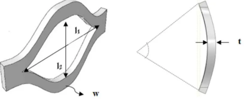
The parameters effective in expanded metal absorbers were defined to investigate the adsorption behavior of the absorbers. The patterns in expanded metal (latticed) absorber are demonstrated by two parameters. l2 denotes the lesser length, and l1 denotes the greater length (Figure 1). Two types
of collapse were observed under quasi-static loads. A distinct plastic collapse occurred in 0 and led to a global buckling and the failure of the structure in the 90-degree angle (Graciano et al., 2012).
Figure 1: Definition of geometric parameters of a cell of expanded metal tube from front view and top view.
2.2 Evaluation of the parameters
The initial peak force (Ppeak), the mean force (Pm), the energy absorption capacity (Ea), and shape
factor () are the parameters used to measure absorption (Eq. 1-3). In addition, there are other parameters: the energy absorbed per unit weight (SEAa E Wa m ). These parameters are important
in system design, where, weight is the constraining factor. The amount of the absorbed energy is the area under the force-displacement curve. The shape factor is the ratio of the mean force to the initial peak force (Graciano et al., 2009).
2
1
( ) d
x
a x
E
F x x (1)2 1 a m E P x x
(2)
m
peak
P P
(3)
2.3 Strain rate
In the transportation industry, researchers look to improve design performance in accidents. There-fore, high-strength steels have replaced the weak ones. It is therefore necessary to better understand the mechanism of the behavior of the structural systems, especially their energy absorption capacity, and how to improve energy capacity under impact loading conditions. The strain rate sensitivity behavior of steel should be addressed in design of the structures. The strain rate sensitivity of a material is of paramount importance in dynamic loadings and should be considered in design. The Johnson-Cook or Cowper-Symonds relationships can be used in this regard (Eq. 4-6) (Jones, 2010a).
( ) ( ) 2 a s t s E t t A
(4)
0
0
2
( ) d
t
s R
c
t t L
(5)0 2 ( ) s R c t L
(6)
where, s is stress, s is strain, and s is the strain rate, E is the elasticity modulus of the model, A and As are the cross-section of the model and the impact mass, c0 is the stress wave propagation
velocity, and t
t and R
t are the reflected and transmitted stress wave, respectively.2.3.1 The Johnson-Cook theory
The strain rate and the temperature are interdependent in the Johnson-Cook model. It is considered a viscoelastic model Johnson and Cook (1983). The model is suitable for strain rates with high
amplitudes and temperature variations, which leads to softening of the model due to the energy dissipation of plastic deformation. This model has a coefficient of strain, strain rate, and temperature. The coefficients are in such a way that strain-hardening rate increases with increasing the strain rate Dietenberger et al. (2005). The Johnson-Cook model considers a nonlinear elastic-plastic material behavior. The simplified Johnson-Cook equation is as follows. The stress-strain curve is oscillating in impact loadings, and the equations 7 and 8 establish a relationship between stress and strainKennan (2005).
n
1
1 Tm
PA B C
(7)
* room
melt room
T T
T
T T
(8)
where, A is the yield stress, B is strain-hardening factor, n is the strain-hardening coefficient, C is
the coefficient of strain rate sensitivity, T is the homologous temperature as defined by the above equation, T is the temperature before dynamic loading, m is the thermal coefficient related to
sof-tening, and Tmelt is the melting temperature Nicholas and Recht (1990).
3 NUMERICAL MODELING
3.1 Finite element model
To construct an expanded metal absorber, a cell was first designed as shown below. The expanded metal absorber was created by putting the cells together. The cells had diameters of l1 1.5 cm and
2
l 1 cm , a thickness of t 1 mm, and the width of w 2 mm.
The structured mesh method was used. The elements were three-dimensional and hex-dominated. The size of each element was considered 1 mm.
3.2 Absorber material
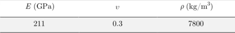
High-strength steel was used for absorbers. The material properties and the stress-strain curve of this type of steel are shown in Table 1. The tensile test curve is shown in Figure 2.
(kg/m3)
E (GPa)
7800 0.3
211
Table 1: The material properties.
The dynamic loading was used. As previously discussed, strain rate of the material should be consid-ered in a dynamic loading. The Johnson-Cook model was used here. The coefficients for high-strength steel are given in Table 2.
m T (oC) m
n C
B(MPa) A(MPa)
1460 1
.234 .0134
600.8 553.1
Table 2: The coefficients of the Johnson-Cook model for steel A611.
3.3 Loading and boundary conditions
The simulated loading was impact loading due to the free fall of the impact mass. Absorber was placed between two rigid plates. The bottom rigid plate was fixed. The upper rigid plate, which had a mass of 25 kg, moved downward at the velocity of 2.6 m/s in the phase-1 tests, and at fall height-dependent velocities in the phase-2 tests. The solution time of the problem was considered 0.034 sec. Given the symmetry of the absorber and to reduce the solution time, only one absorber column was considered. The absorber had 15 columns. Loading was applied on one column, and the values of initial peak force and absorbed energy was obtained. The values were multiplied by 15 to obtain the actual values. When the absorber collapsed, the cells were in contact with each other. Therefore, a friction coefficient of 2.0 was considered to account for the friction force.
3.4 Specimen specification
The models were investigated for the cell angle of 0 and a variable number of longitudinal cells. Boundary conditions and the loading type was the same for all models. EMT indicates the model label in Table 3. is the cell angle, N_C is the number of circular cells (with increasing of number of circular cells, the diameter of specimen is increased), N_L is the number of longitudinal cells (longitudinal cells are number of cells that they are along the length of specimens. With increasing of number of the longitudinal cells, the length of specimen is increased), D is the model diameter, L is
length, t is the wall thickness, m is the impact mass, and v is the impact velocity.
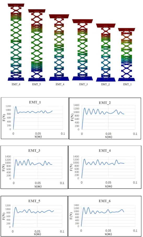
3.5 Numerical results and discussion
The area under the force-displacement curve represents the amount of absorbed energy. The absorbers with cells angle of 0 were studied. Their force-displacement curves and their collapse type are presented in Figure 3.
L(cm) N_L m(kg) v(m/s) b(mm) t(mm) D(cm) N_C specimen 16.5 15 25 2.6 2 1 10 15 0 EMT_1 17.5 16 25 2.6 2 1 10 15 0 EMT_2 18.5 17 25 2.6 2 1 10 15 0 EMT_3 19.5 18 25 2.6 2 1 10 15 0 EMT_4 20.5 19 25 2.6 2 1 10 15 0 EMT_5 21.5 20 25 2.6 2 1 10 15 0 EMT_6
Table 3: Specification of Specimens.
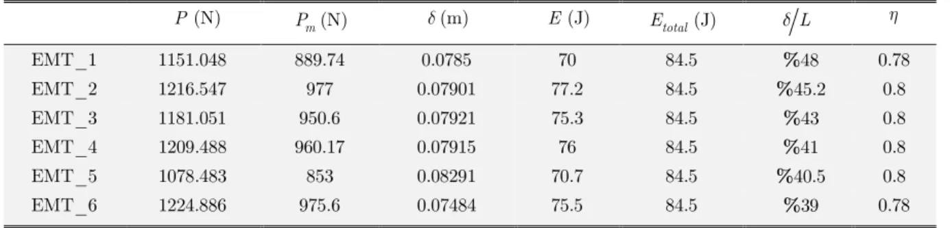
The initial peak force diagram and its variations were relatively similar for all the absorbers. The area under the force-displacement curve gives the amount of absorbed energy which was obtained by integration. Results are shown in Table 4.
L total E (J) E(J) (m) m P (N) P(N) 0.78 %48 84.5 70 0.0785 889.74 1151.048 EMT_1 0.8 %45.2 84.5 77.2 0.07901 977 1216.547 EMT_2 0.8 %43 84.5 75.3 0.07921 950.6 1181.051 EMT_3 0.8 %41 84.5 76 0.07915 960.17 1209.488 EMT_4 0.8 %40.5 84.5 70.7 0.08291 853 1078.483 EMT_5 0.78 %39 84.5 75.5 0.07484 975.6 1224.886 EMT_6
Table 4: Numerical results.
Kinetic energy was created due to the fall of the impact mass. The total energy generated by the fall of the impact mass can be obtained from the following equation
2
1 2
total
E mv (9)
To calculate the average force, the amount of energy absorbed was divided by the crushing length. Results showed that the collapse of the absorber was symmetric which caused the force-displacement curve to be stable. The cells were folded on each other due to the effect of the axial load, and thereby, absorbed the impact energy. One of the important parameters in energy absorbers is the shape factor or the crushing force efficiency. The factors closer to 1 indicate a more efficient absorber and a stable collapse. Shape factors were calculated for all models. As seen in Table 4, the shape factors were close to 1 which indicated that the mean force and the initial peak force were close, and consequently, the force-displacement was uniform, and the energy absorption capacity was suitable.
In the second phase of the tests, the initial velocity parameter was modified by increasing the height of the impact mass. The results of the absorbed energy and the crushing length were examined for 5 models which had identical dimensions and mechanical properties.
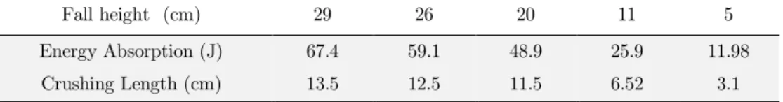
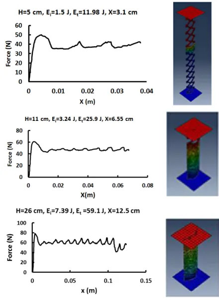
The 25-kilogram impact mass was released from certain heights 5, 11, 20, 26 and 29 cm respectively on the model with a diameter, length, and thickness of 10 cm, 15 cm, and 1 mm, respectively. The simulations and the force-displacement curves for three of the tests are shown in Figure 4. Given the symmetry of the absorber and to reduce the solution time, only one absorber column was considered. The absorber had 8 columns. Loading was applied on one column, and the values of initial peak force and absorbed energy was obtained. The values were multiplied by 8 to obtain the actual values.
The amount of energy absorption and the crushing height by different heights of the impact mass is shown in Table 5.
5 11
20 26
29 Fall height (cm)
11.98 25.9
48.9 59.1
67.4 Energy Absorption (J)
3.1 6.52
11.5 12.5
13.5 Crushing Length (cm)
Table 5: Numerical results.
As can be seen, when the height of the impact mass was 11 cm, the crushing height was 6.52 cm which had the closest value to the model height in the folded condition (closure of the cells) and had the best loading conditions for energy absorption. Greater loading heights would cause buckling as well as undesirable, unpredicted and irregular deformations.
4 EXPERIMENTAL INVESTIGATION
Figure 4: Force-Displacement for Height 5, 11 and 26 cm.
4.1 Experimental test setup
In the drop hammer setup, a weight with known mass was released from a certain height to crush the absorber. The crushing force and length was measured by the sensor located on the machine. An accelerometer was mounted on the impact mass. The accelerometer was connected to a computer which showed the acceleration-time diagram (Figure 5).
4.2 Model specifications
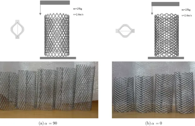
In the experimental tests, nine models were first built to examine the effect of length of the model in the same impact velocities. Figure 6 shows the models with cell angles of 0 and 90 which differed only in number of longitudinal cells. High-strength steel sheet were used (Table 1 and Figure 2).
Figure 5: Drop hammer setup and the acceleration sensor.
(a)90 (b) 0
Figure 6: Loading conditions and two type of specimens 0 and 90 with different number of longitudinal cells.
Models were investigated in two cases of 0 and 90 and different number of longitudinal cells. The specifications of the models are shown in Table 6. Wm is the mass of the models.
4.3 Experimental results and discussion
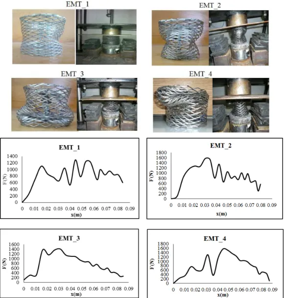
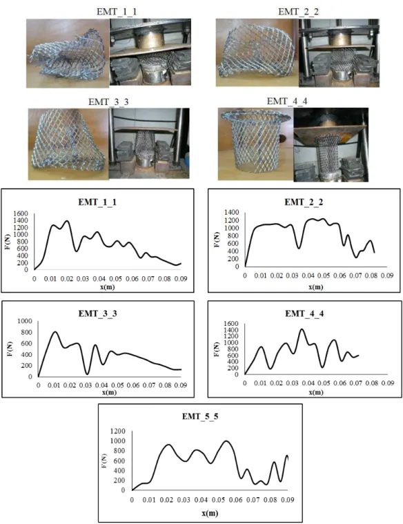
The collapse results of the expanded metal models with the cell angle of 0 and the force-displace-ment curves are shown in Figure 7. The collapse results of the expanded metal models with the cell angle of 90 and the force-displacement curves are shown in Figure 8.
specimen N_C N_L D(cm) L(cm) t(mm) v(m/s) m(kg) Wm(gr)
EMT_1 0 15 15 10 16.5 1 2.6 25 110
EMT_2 0 15 16 10 17.5 1 2.6 25 120
EMT_3 0 15 17 10 18.5 1 2.6 25 130
EMT_4 0 15 18 10 19.5 1 2.6 25 140
EMT_1_1 90 26 8.5 10 17.5 1 2.6 25 120
EMT_2_2 90 26 9 10 18.5 1 2.6 25 130
EMT_3_3 90 26 9.5 10 19.5 1 2.6 25 140
EMT_4_4 90 26 10 10 20.5 1 2.6 25 150
EMT_5_5 90 26 10.5 10 21.5 1 2.6 25 160
Table 6: specifications of specimens with 0 and 90.
Figure 7: Collapse of models with cell angle 0 and the force-displacement diagrams.
Figure 8: Collapse of models with cell angle 90 and the force-displacement diagrams.
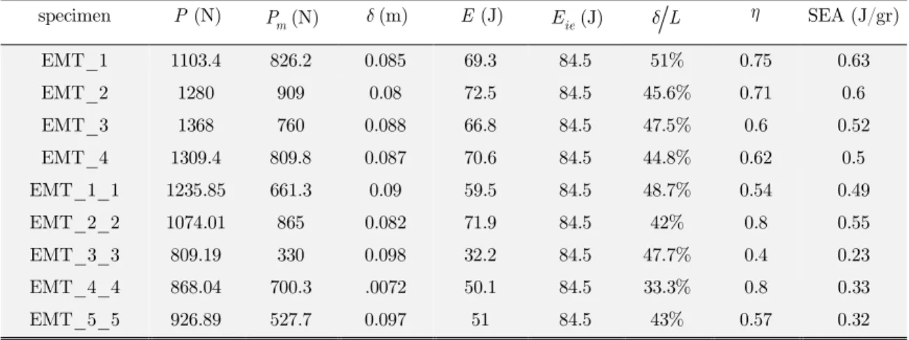
initial peak force was suitable and was close to the mean force. The calculated energy absorption capacity showed this too. The energy absorption capacities were calculated for all models (Table 7). All models had a relatively similar amount of energy absorption capacity and were only different in the crushing value with respect to the initial length, which indicated the effectiveness of the absorber. The absorbers with cell angle of 90 buckled due to their longitudinal strength. The experiments showed that all models collapsed due to the global buckling. The buckling caused the absorbers to have unsuitable energy absorption and an inefficient initial peak and mean forces (Table 7). The results of the experiments also showed that in the absorbers with the cell angle of 0, bucking would not occur if the length to diameter ratio of the absorber was less than 2.15.
SEA (J/gr) L ie E (J) E (J) (m) m P (N) P(N) specimen 0.63 0.75 51% 84.5 69.3 0.085 826.2 1103.4 EMT_1 0.6 0.71 45.6% 84.5 72.5 0.08 909 1280 EMT_2 0.52 0.6 47.5% 84.5 66.8 0.088 760 1368 EMT_3 0.5 0.62 44.8% 84.5 70.6 0.087 809.8 1309.4 EMT_4 0.49 0.54 48.7% 84.5 59.5 0.09 661.3 1235.85 EMT_1_1 0.55 0.8 42% 84.5 71.9 0.082 865 1074.01 EMT_2_2 0.23 0.4 47.7% 84.5 32.2 0.098 330 809.19 EMT_3_3 0.33 0.8 33.3% 84.5 50.1 .0072 700.3 868.04 EMT_4_4 0.32 0.57 43% 84.5 51 0.097 527.7 926.89 EMT_5_5
Table 7: Experimental results of specimens with 0 and 90.
In the second phase of the tests, the height of the impact mass was increased to increase the initial velocity of the collision. The type of collapse and the crushing length for the expanded metal tubes were compared for 5 models with identical dimensions and mechanical properties. The heights of the fall are 5, 11, 20, 26 and 29 cm respectively.
The shape of the plate used for this test was similar to the first phase. The tests were conducted for models with zero cell angles.
As can be seen in Figure 9, in the loading with the height of 5 cm, the expanded metal tube was not fully folded, and its mesh was not fully closed, and empty spaces between them could be observed. This showed that in this case of loading, the model had not used all its energy absorption capacity and can also be suitable for larger loadings. In the loading with a height of 11 cm, however, the tube was fully folded, and no space was observed among the mesh. Also, the edges of the mesh were tangent to each other and were not compressed, and therefore, no buckling happened. However, at higher heights, local buckling was observed in the model. For example, at a height of 26 cm, the edges of all cells were crushed into each other, and a local buckling was observed. At higher heights, in addition to the folding of the tubes and the closure of the mesh, the edges were pressed to each other and occasionally crushed each other, and buckling was observed. This means that the loading was greater than the energy absorbing capacity of the tube. The load-displacement curves for all the tested heights were reported. The area under the curve was then calculated using software and reported as the absorbed energy of the model.
Figure 9: Experimental results of specimens with 0 and different height.
Test results obtained from different height showed that the height of 11 cm was the best height for the model to fully absorb the energy (Table 8).
5 11
20 26
29 Height (cm)
11.4 24.5
47.6 52.7
66.3 Energy absorption (J)
8.6 9.5
10.6 11.5
13.5 Crushing Length (cm)
Table 8: Experimental result of specimens with 0.
In the third phase of the tests, the effect of the wall on the crushing length and the type of collapse was studied.
Fourteen models with different specifications were tested. The effect of angle and wall on the type of collapse, the crushing length, and the amount of absorbed energy was examined.
Four groups of models were tested as follows:
G1. The models of the first column of Figure 10 were separate concentric cylinders located inside each other and had a cell angle of 0. They were four-walled, three-walled, two-walled, and single-walled, respectively.(G1-t4, G1-t3, G1-t2 and G1-t1)
G2. The models of the second column of Figure 10 were separate concentric cylinders located inside each other and had a cell angle of 90. They were four-walled, three-walled, two-walled, and single-walled, respectively. (G2-t4, G2-t3, G2-t2 and G2-t1)
G3. The models of the third column of Figure 10 were four-walled, three-walled and two-walled, respectively but the expanded sheet is twisted seamlessly. They had a cell angle of 90. (G3-t4, G3-t3 and G3-t2)
G4. The models of the fourth column of Figure 10 were four-walled, three-walled and two-walled, respectively but the expanded sheet is twisted seamlessly. They had a cell angle of 0. (G4-t4, G4-t3 and G4-t2)
Figure 10: Multiwall specimens with different α and different layers.
For all tested models, the height of the impact mass was 22 cm. Dimensions and properties of the models were exactly like the ones before.
The performed tests and the force-displacement curves of the models are shown in Figures 11 and 12.
The crushing lengths of the models are shown in Table 9.
t1 t2 t3 t4
G1 12.93 6.2 2.91 1.32
G2 12.28 1.91 0.85 0.76
G3 12.28 4.31 2.6 1.44
G4 12.93 3.57 1.32 0.85
Table 9: The crushing lengths of the specimens (cm)
Figure 11: collapse of specimens of G1 and G2.
Figure 12. Collapse of specimens of G3 and G4.
The models of the group 1 had the maximum crushing due to the discontinuity between the cylinders and a zero cell angle. The models of the group 2 had a cell angle of 90, and their crushing length was less than 1, because, due to collision, they buckled locally which prevented further crushing. The models of the groups 3 and 4 showed greater resistance against impact, because the cell crushed each other and become tied. Global buckling was also observed in group 3 which was due to the 90-degree cell angle and the continuity of the walls.
5 COMPARISON OF EXPERIMENTAL AND NUMERICAL RESULTS
In this section, the results of numerical simulations and experimental tests are compared. First, the absorbers with cell angle of 0 were numerically studied, and the absorbed energy, initial peak force, average force, and other parameters were investigated. Then, these absorbers were studied experimentally. As mentioned before, absorbers with cell angle of 0 were much more efficient compared to those with cell angle of 90. Therefore, to determine the difference between the results of numerical simulations and the experimental tests, the absorbers with cell angle of 0 were compared. The absorbed energy, initial peak force, and the average force obtained numerically and experimentally were then compared. The results are shown in Table 10.
E (J) m P (N) P(N) specimen Numerical Experimental Numerical Experimental Numerical Experimental 69.3 70 826.2 889.74 1151.05 1103.44 EMT_1 72.5 77.5 909 977 1216.547 1280 EMT_2 66.8 75.5 760 950.6 1188.051 1368 EMT_3 70.6 76 809.8 960.17 1209.49 1309.41 EMT_4
Table 10: Comparison of experimental and numerical results.
In this section, the results of experimental tests and numerical simulation were compared. Experi-mental tests require time and money, and therefore, can be replaced by numerical simulations. Re-sults showed that force-displacement curves obtained by numerical simulations were in a good agreement with those obtained from the experimental tests. Other important parameters, i.e. the initial peak force, average force, and the absorbed energy, were calculated for both cases and com-pared with each other. As can be seen, the values were somehow consistent with each other, how-ever, errors were observed in some cases.
It was also observed that the models with zero cell angle had a symmetric collapse. Multi-walled expanded metal cylinders had a considerably higher strength under impact loading.
6 CONCLUSION
In this study, drop hammer free fall setup was used to apply impact loading on expanded metal steel tubes. Simulation was performed using ABAQUS. The results of experimental tests and numerical simulations, as well as the collapse shapes of the models, showed that the expanded metal tubes can be used as energy absorbers in the industry. In the present research, for the first time, when these structures were subjected to impact loading, it was found that despite their low weight, they can absorb the energy of the collision due to their mesh and multiple joints and nodes. The collisions led to a symmetric collapse and complete crushing in such expanded metal structures. Therefore, it can be concluded that:
average force. The calculation of the shape factor or the crushing force efficiency also indicated this matter. The calculated shape factors showed that the expanded metal energy absorber had a high efficiency of energy absorption.
• Increasing the number of longitudinal cells did not significantly affect the initial peak force and the average force. The crunching of the cells led to the energy loss. Therefore, the energy absorp tion capacity can be increased by increasing the number of longitudinal cells.
• Angle of cells significantly affected the behavior of the absorber. As observed, the absorbers with the cell angle of =0 had a symmetric collapse mechanism and a uniform force-displacement curve. These absorbers are also very suitable in terms of the initial peak force and energy absorp tion capacity. On the other hand, all the absorbers with the cell angle of =90 underwent buck ling, and their force-displacement curve did not have a suitable continuity. It can be concluded that the expanded metal absorbers with the cell angle of =0 were much more efficient and had a high energy efficiency.
• One of the most important parameters in energy absorbers is the specific energy or energy effi-ciency (SEA). This parameter is the ratio of the absorbed energy and the absorber per absorber mass. Expanded metal absorbers have a low weight and absorb a lot of energy. It was also observed that increase in the shape factor or the crushing force efficacy increased the specific energy.
• The results of numerical simulation showed that the amount of absorbed energy, initial peak force, average force, and the force-displacement curve were in a good agreement with the results of the experimental tests. The numerical model can therefore be a good alternative in design process of such absorbers.
• Increase in wall of the expanded metal cylinders increased the amount of absorbed energy and reduced the crushing length significantly. Compared to multi-walled models with 90 degree cell angle, multi-walled models with zero cell angle had larger crushing length and were more flexible under impact loading. They are considered as more suitable absorbers. The models with 90-degree cell angle acted rigidly and cannot be used as absorbers.
• Expanded metal cylinders can be used in industry as a modern absorbers because despite their very low weight, that can undergo a symmetric collapse under impact loadings and crush to their ends. They also significantly reduce the initial peak force.
References
Alghamdi, A.A.A., (2001). Collapsible impact energy absorbers: an overview. Thin-Walled Structures 9: 189–213. Dietenberger, M., Buyuk, M., Kan, C.D., (2005). Development of high strain-rate dependent vehicle model. LS-DYNA Anwenderforum, Bamberg.
Ghamarian, A., Zarei, H.R., Abadi, M.T., (2011). Experimental and numerical crashworthiness investigation of empty and foam-filled end-capped conical tubes. Thin-walled Structures 49: 1312–1319.
Graciano, C., Martinez, G., Smith, D., (2009). Experimental investigation on the axial collapse of expanded metal tubes. Thin-Walled Structures 47: 953-961.
Graciano, C., Martinez, G., Gutirrez, A., (2012). Failure mechanism of expanded metal tubes under axial crushing. Thin-Walled Structures 51: 20-24.
Gupta, N.K., Venkatesh, A., (2006). A study of the influence of diameter and wall thickness of cylindrical tubes on their axial collapse. Thin-Walled Structures 44: 290–300.
Johnson, G.R., Cook, W.H., (1983). A constitutive model and data for metals subjected to large strains, high strain rates and high temperatures. Proceedings of the Seventh International Symposium on Ballistics, Hague, Netherlands, 541-547.
Jones, N., (2010a). Dynamic energy absorption and perforation of ductile structures. International Journal of Pressure Vessels and Piping 87: 482-492.
Jones, N., (2010b). Energy-absorbing effectiveness factor. International Journal of Impact Engineering 37: 754–765. Kennan, Z.A., (2005). Determination of the constitutive equations for 1080 steel and VascoMax 300, chapter 2 of thesis: Background and Theory, 6-33.
Lau, S.T.W., Said, M.R., Yaakob, M.Y., (2012). On the effect of geometrical designs and failure modes in composite axial crushing: A literature review. Composite Structures 94: 803–12.
Li, Z., Yu, J., Guo, L., (2012). Deformation and energy absorption of aluminum foam-filled tubes subjected to oblique loading. International Journal of Mechanical Sciences 54: 48–56.
Martínez, G., Graciano, C., Teixeira, P., (2013). Energy absorption of axially crushed expanded metal tubes. Thin-Walled Structures 71: 134-146.
Nia, A.A., Hamedani, J.H., (2010). Comparative analysis of energy absorption and deformations of thin walled tubes with various section geometries. Thin-Walled Structures 48: 946–954.
Nicholas, T., Recht, R.F., (1990). Introduction to impact phenomena. In: Zukas, J.A. (Ed.), High Velocity Impact Dynamics. Wiley, INC, New York, 8-25.
Olabi, A.G., Morris, E., Hashmi, M.S.J., (2007). Metallic tube type energy absorbers a synopsis. Thin-Walled Struc-tures 45: 706–26.
Qu, H., Huo, J., Xu, C., Fu, F., (2014). Numerical studies on dynamic behavior of tubular T-joint subjected to impact loading. International Journal of Impact Engineering 67: 12-26.
Song, J., Chen, Y., Lu, G., (2013). Light-weight thin-walled structures with patterned windows under axial crushing. International journal of Mechanical Sciences 66: 239-248.
Tai, Y.S., Huang, M.Y., Hu, H.T., (2010). Axial compression and energy absorption characteristics of high-strength thin-walled cylinders under impact load. Theoretical and Applied Fracture Mechanics 53: 1–8.
Zhang, X., Cheng, G., You, Z., Zhang, H., (2007). Energy absorption of axially compressed thin-walled square tubes with patterns. Thin-Walled Structures 45: 737–46.