ISSN 0104-6632 Printed in Brazil
Brazilian Journal
of Chemical
Engineering
Vol. 21, No. 02 pp. 345 - 355, April - June 2004
ANALYSIS AND SIMULATION OF THE
DRYING-AIR HEATING SYSTEM OF A BRAZILIAN
POWDERED MILK PLANT
C. P. Ribeiro Jr. and M. H. C. Andrade
*Departamento de Engenharia Química, Universidade Federal de Minas Gerais, Rua Espírito Santo 35, Centro, Phone +(55)(31) 3238-1780, Fax +(55)(31) 3238-1789, CEP 30160-030, Belo Horizonte - MG, Brazil.
E-mail: [email protected]
(Received: February 13, 2003 ; Accepted: November 27, 2003)
Abstract - Aiming at simulating air-heating systems, two algorithms were developed for the calculation of finned elliptical-tube heat exchangers, whose basic difference lies in the kind of hot fluid employed: saturated steam or hot liquid. In both cases, a crossflow unit, in which the cold fluid is mixed and always flows on the shell side, is considered. The hot fluid may exhibit multiple passes in the tubes and is assumed unmixed, except for the region between the passes. A comparison between calculated results and operating data on industrial exchangers indicated the adequacy of the algorithms developed. The codes were then introduced into the ASPEN Plus shell, enabling simulation of the steady-state operation of the whole drying-air heating system of a powdered milk plant. Moreover, a sensitivity analysis of this system was conducted for one of its operating parameters and the existence of an optimal value for this variable was clearly shown.
Keywords: heat exchanger, elliptical tubes, fins, ASPEN.
INTRODUCTION
Drying is the last step in the process of powdered milk production, and since the Second World War, the spray drying technique has been used in the vast majority of the dairy industries. This technique consists in transforming the liquid feed stream into a large number of small droplets, which are exposed to a heavy flow of hot gas in a drying chamber.
In the dairy industries, atmospheric air is used as the drying gas. It is filtered and then heated prior to being fed into the dryer at a temperature which ranges from 150 to 220oC (Varnam and Sutherland, 1994; Schuck, 2002). Indirect heating systems, comprising high-efficiency finned-tube exchangers and saturated steam, are normally employed, though units with hot oil as the heating fluid can also be found. As an alternative, air can be heated by direct
contact with combustion gases from a burner (Jansen and Elgersma, 1985; Kelly et al., 1989). Despite the substantially lower capital investment and the high thermal efficiency associated with direct heating, it is not recommended due to the likely contamination of powdered milk brought about by the nitrogen oxides from the combustion gases, which can result in the formation of cancerous chemicals, such as nitrosamines (Caric, 1994). A more detailed description of the air-heating systems in the dairy industry is given by Knipschildt and Andersen (1994).
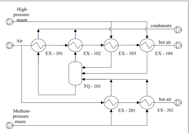
work, a study was conducted on the industrial air-heating system installed at Embaré Indústrias Alimentícias S. A., a Brazilian dairy company located in Lagoa da Prata, Minas Gerais. This system, illustrated in Figure 1, provides two drying systems with hot air and is composed of six heat exchangers and a flash tank. All the exchangers have a rectangular shell and elliptical tubes, inside which the hot fluid flows.
Units EX-201 and EX-202 work in series and are fed with saturated steam at 13.2 kgf/cm2, supplying hot air to the smaller drying system, which is responsible for one-third of the total amount of powdered milk produced in the plant. The other exchangers are related to the main drying system. Only the last two units, EX-103 and EX-104, use steam at 21.5 kgf/cm2 as heating fluid. The condensate from these exchangers, together with that
formed in both EX-201 and EX-202, feeds the flash tank, TQ-101, in which part of the feed (high-pressure liquid) vaporises on account of the low operating pressure of the tank (2.5 kgf/cm2). The steam produced in TQ-101 is the heat source for EX-102, whereas the liquid fraction from this tank is the hot fluid for the first exchanger in the arrangement, EX-101.
The ASPEN Plus environment (Evans et al., 1979), which has already been employed to simulate other industrial plants (Douglas and Young, 1991; Ong’iro et al., 1996; Rachid and Caño Andrade, 2001; Ribeiro and Caño Andrade, 2003), was chosen for analysis of the system described above. Since a built-in model block for simulating rectangular shell exchangers with finned elliptical tubes is not available in ASPEN, one was developed in this work and subsequently introduced into the simulator.
EX - 102
TQ - 101
EX - 103 EX - 104
EX - 101
EX - 201 EX - 202
High-pressure
steam
Air
Medium-pressure
steam
condensate
hot air
hot air
D2,ext
D1,ext
D2,int
D1,int
B
C t
Figure 2: Finned elliptical tube.
DESCRIPTION OF ALGORITHMS in which hsl and htb are the average heat-transfer
coefficients on the shell and tube sides, respectively, Afinis the area of the fins, Aext and Aint are respectively
the outer and inner surface area of the tubes. The two codes developed for simulating finned
elliptical-tube exchangers consider a crossflow unit with a rectangular shell, where the cold fluid flows and is assumed to be completely mixed. In the tubes, the fluid is assumed to be unmixed and may have more than one pass. All fins are rectangular in shape. The main difference between the two codes is the kind of heating fluid: hot liquid or saturated steam.
From Figure 2, the different areas in eq. (2) can be quantified as follows:
Regardless of the nature of the hot fluid, the heat-transfer rate in the unit, Q, is given by the classic equation (Incropera and DeWitt, 1996):
T
Q U A f LMTD (1)
where U is the overall heat-transfer coefficient, AT is
the total area of the finned tubes, LMTD is the logarithmic mean temperature difference and f its correction factor for the actual flow pattern in the exchanger.
In order to calculate the overall heat-transfer coefficient one must take into account the mean fin efficiency, K. Considering the total area of the finned tubes and neglecting the heat-transfer resistances owing to conduction through the tube wall, fouling and contact resistance between the tube and fins, U is estimated by the following equation (Hashizume, 1986):
T
sl fin ext tb int
A
1 1 1
U h A A h A
§ · §
¨K ¸ ¨
© ¹ ©
T
A ·
¸ ¹
xt
(2)
T fin e
A A A (3)
fin fin tb 1,ext 2,ext
A 2n Ln
D D
BC t(B C)
4
ª§ S · º
«¨ ¸ »
© ¹
¬ ¼
(4)
ext tb fin 2,ext
2 2
ext 0
A 4n L 1 n t D
1 sen d
S
H T T
³
(5)
2 2
2,ext 1,ext ext
2,ext
D D
D
H (6)
int tb 2,int
2 2
int 0
A 4n LD
1 sen
S
d
H T
³
T(7)
2 2
2,int 1,int int
2,int
D D
D
Parameter rc is given by the following equation:
where nfin is the number of fins per tube length, ntb is
the number of tubes in the exchanger, L is the tube
length and H is the eccentricity of an ellipse.
^
`
c 1 2
r min f T ,f T (16)
The mean fin efficiency was estimated by means of the expression developed by Suyi and Shizhou (1995) for the efficiency of rectangular fins in an elliptical tube as a function of the polar coordinate,T:
1 c 1 0
1 0 1 c
0
2 2
0 0 1 c
c 0
1 c 0 0
I mr K mr
2r I mr K mr
I mr K mr
m r r
I mr K mr
ª¬ T º ¼ ½
° °
° °
T ° ª¬ T º¼ °
K T ® ¾
ª T °º ª¬ T º¼ °
¬ ¼ ° °
° ª¬ T º¼ °
¯ ¿ (9) 2 1 2 n B 2 f B
y k x
2
ª D T º
« »
¬ ¼
T
ª § · º
« T ¨ T E T¸ »
© ¹ ¬ ¼ (17) 2 n 2 2 2
C 2 y
k f
x C
ª T º
« »
¬ ¼
T
ª T D T º ª E T º¬ ¼ ¬ ¼
(18) where sl fin 2h m
k t (10)
in which kn is the slope of the ellipse’s curvature
radius 1,ext n 2,ext D k D cotg
T (19)
In eq. (9) and (10), I0 and I1 are respectively the
modified Bessel functions of the first kind of order zero and one; K0 and K1 refer to the modified Bessel
functions of the second kind of order zero and one, respectively (Boyce and Di Prima, 1994) and kfin is
the thermal conductivity of the fins. Parameter r0 is
the curvature radius of an ellipse:
According to the concept of mean value of a function over a given interval of its domain, it follows that 2 0 8 d S
K K T
S
³
T (20)2 2
0
r T ª T D T º ª T E T º¬x ¼ ¬y ¼ (11)
For the average heat-transfer coefficients, the value related to the shell side was estimated using the empirical correlation presented by Ilgarubis et al. (1988) for a bundle of finned elliptical tubes:
where x(T) and y(T) are the parametric equations of the ellipse
2,ext
D
x c
2
T osT (12)
1 2,ext 0.65 0.36
2 1,ext
S D Nu 0.06Re Pr
S D (21)
1,ext
D y
2
T senT (13)
In eq. (21), Nu, Re and Pr are respectively the Nusselt, Reynolds and Prandtl numbers and S1 and
S2 are the transverse and longitudinal bundle pitches.
All physical properties should be evaluated at the fluid inlet temperature, and the reference velocity is calculated in relation to the minimum bundle cross section (Amin). The characteristic dimension for
evaluating the dimensionless groups, Deq, is given by
andD(T) and E(T) are the parametric equations of the ellipse’s evolute (Simmons, 1987)
2 22,ext 1,ext 3 2,ext
D D
cos 2D
D T T (14)
2 21,ext 2,ext 3 1,ext
D D
sen 2D
E T T (15) eq min transv
transv 2T
4A n B n 1 S B
D
A
ª º
where ntransv is the number of tubes in the transverse
direction of the bundle.
In eqs. (26) to (28), G is the condensate film thickness, \ is the angle of the tube and Z is the dimensionless film thickness.
For the tubes side, when the heating fluid is a hot liquid, the heat-transfer coefficient is calculated by the equation below, related to turbulent forced convection in cylindrical tubes (Incropera and DeWitt, 1996):
Both algorithms calculate the cold fluid outlet temperature by means of a heat balance, according to which the variation in fluid enthalpy is equal to the amount of energy transferred within the unit. Assuming ideal-gas behaviour for the cold fluid and adiabatic operation, we have
0.8 0.4 l l
Nu 0.023Re Pr (23)
Here the liquid properties are evaluated at the mean film temperature and the characteristic dimension employed is the hydraulic or equivalent diameter of the elliptical tubes:
c,out
c,in T
c c
T
QF
³
Cp T dT 0 (29)For the exchanger operating with saturated steam, it is assumed that there is no pressure drop on the tube side, so the steam temperature remains constant throughout the equipment, which leads to a unitary correct factor for the LMTD (Incropera and DeWitt, 1996). Assuming total condensation, an initial value for the cold fluid outlet temperature is generated. This initial value is used for evaluating the mean fin efficiency, and thus the overall heat-transfer coefficient can be determined by eq. (2). Upon substituting eq. (1) into eq. (29) and solving the resulting expression iteratively by Newton’s method (Mathews, 1992), a new estimate for the cold fluid outlet temperature is obtained. With this new estimate, the value of
K
is recalculated by eqs. (9) to (20) and the iteration circuit is completed. Once the outlet temperature for the cold fluid converges, the amount of steam that actually condenses is determined by a heat balance. 1,int eq 2 2 int 0 D D4 S 1 sen
S
H T T
³
d(24)
On the other hand, the heat-transfer coefficient associated with saturated steam condensation inside vertical tubes is calculated using the Nusselt theory on a vertical surface (Marto, 1991):
1 3 4
l l v
l tb
l s w l
g L 0.943k
h
L T T k
ªU U U J º
« »
P
« »
¬ ¼ (25)
where kl, Ul and Pl are the condensate thermal
conductivity, density and viscosity, respectively; Uv
is the steam density; g is the gravitational acceleration;
J is the latent heat of vaporisation and Ts and Tw are
respectively the saturation and wall temperatures.
When a hot liquid constitutes the heat source, the temperature of adiabatic mixture is used as the initial value for the stream outlet temperatures. Assuming once again adiabatic operation, all energy supplied by the hot fluid has to be transferred to the cold one, hence, neglecting the effect of pressure on the liquid enthalpy:
However, if condensation takes place in either horizontal or slanted tubes, the equation presented by Fieg and Roetzel (1994) for laminar condensation in slanted elliptical tubes is utilised:
1 l tb
0
k
h S G T
S
³
dT (26) 2 141,int
l s w l
2
2,int l
D
3 T T k
Z D g cos
ª P º
G T « T »
U J \
« » ¬ ¼ (27) h,out h,in T h h T
QF
³
Cp T dT 0 (30)By sustituting eq. (1) into eqs. (29) and (30) and solving the resulting system of non-linear equations using the Newton-Raphson method (Mathews, 1992), the outlet temperature of each fluid is calculated. In this case, the correction factor for the LMTD is evaluated with the aid of the equations presented by Bowman et al. (1940). All necessary integrals are evaluated numerically by the Gaussian quadrature method (Mathews, 1992). As a
4 3 2 2 int 1 1 2 2 3 3 int 0 1 sen 4 Z 3 sensen 1 sen d
T
§ H T·
¨ ¸
T
¨ T ¸
© ¹
I H I I
³
convergence criterion, the residue of all equations is required to be less than 10-6.
RESULTS AND DISCUSSION
Validation of the Algorithms
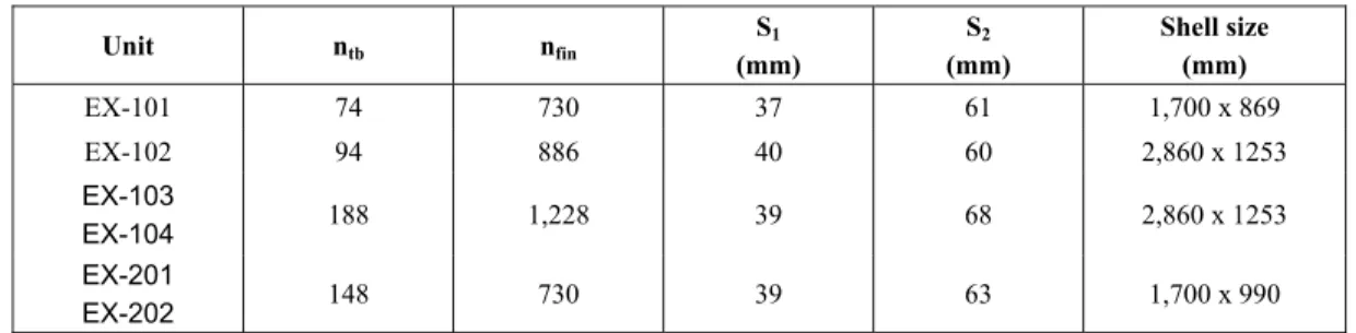
In order to validate the codes developed, an individual simulation of the units related to the heating system (Figure 1) was carried out. All exchangers have 36 x 14 mm (external dimensions) elliptical tubes, arranged in a triangular layout. Their walls are 2.0 mm thick. All fins are rectangular, with dimensions of 55 x 26 mm and a thickness of 0.23 mm. The hot fluid flows vertically in units EX-103 and 104 and horizontally in the others. In EX-102, the tubes have a 5o slope in relation to the horizontal axis. Additional design parameters of the simulated exchangers are listed in Table 1.
In the industrial plant, units EX-103 and EX-104 are, in fact, identical exchangers installed one immediately after the other. This is also the case for units EX-201 and EX-202. As a result, during the simulation each of these pairs was represented as a single unit, twice as wide as the original exchanger with twice as many tubes. The operating conditions of the units, which correspond to the input data for the individual simulation, are presented in Table 2.
The calculated air outlet temperatures are compared with averaged operating data from the industrial plant (Ribeiro, 2001) in Table 3. The biggest deviation, 6.7%, is associated with EX-101, which may be a consequence of the fact that, for this unit alone, one of the heat-transfer coefficients is estimated with an equation related to cylindrical tubes, inasmuch as no correlation for calculating the h value due to forced convection in elliptical tubes was found in the literature. Nevertheless, the agreement verified between calculated and operating
values for the other exchangers attests to the validity of the algorithms developed.
Simulation of the Air-Heating System
In view of the results of the individual simulations, the codes developed were introduced into ASPEN to enable simulation of Embaré’s air-heating system. The tank, TQ-101, was represented by the ASPEN built-in model block FLASH2, which performs rigorous multicomponent liquid-vapour equilibrium calculations. All physical property evaluations in the developed codes were carried out using only ASPEN models, so as to main the consistency of the calculations.
The input data for the simulation in this case are the operating pressure in tank TQ-101 and the conditions (temperature, pressure and flow rate) of the air streams fed into EX-101 and EX-201/2, apart from the data related to the steam streams in EX-201/2 and EX-103/4. Since the modular approach is adopted in ASPEN for the calculations (Motard et al., 1975), an initial value for the system tear stream, namely the cold fluid in EX-103/4, had to be provided in order to avoid convergence problems.
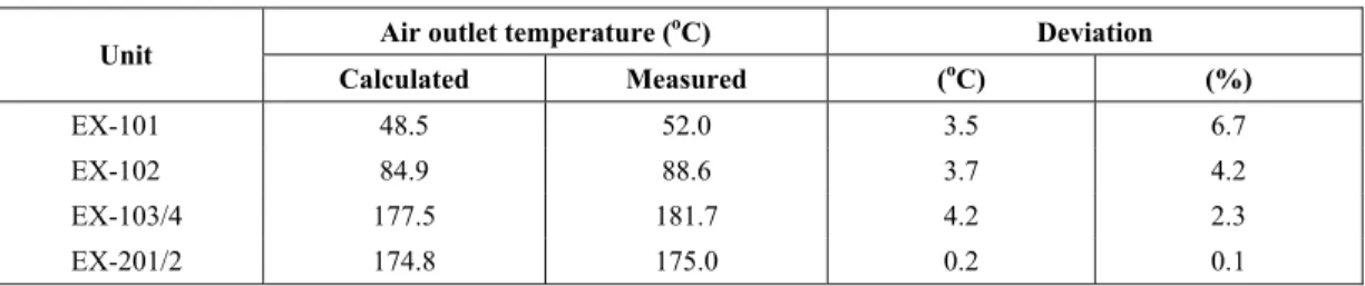
The results for the global simulation of the air-heating system are shown in Table 4. For the exchangers arranged in series, any deviation in the calculation for one piece of equipment will directly affect the results obtained for the next, so the absolute difference between calculated and operating outlet temperatures increases in the direction of the air flow. As a consequence, the deviations from the operating data are larger than those observed in the individual simulation of the units, but, nonetheless, quite acceptable as far as simulation of the industrial process is concerned, since the temperatures of the air streams which will actually be fed into the drying systems are predicted with an error less than 2.5%.
Table 1: Design parameters of the heat exchangers.
Unit ntb nfin
S1
(mm)
S2
(mm)
Shell size (mm)
EX-101 74 730 37 61 1,700 x 869
EX-102 94 886 40 60 2,860 x 1253
EX-103
EX-104 188 1,228 39 68 2,860 x 1253 EX-201
Table 2: Operating conditions of the simulated units.
Flow rate (kg/h) Inlet temperature (oC)
Unit
Hot fluid Cold fluid Hot Fluid Cold Fluid
EX-101 2,470 34,697 129.2 31.0
EX-102 584 34,697 129.2 52.0
EX-103/4 1,752 34,697 215.1 88.6
EX-201/2 1,302 17,549 191.4 31.0
Table 3: Results of the individual simulations of the exchangers.
Air outlet temperature (oC) Unit
Calculated Measured
Deviation
(%)
EX-101 48.5 52.0 6.7
EX-102 88.3 88.6 0.3
EX-103/4 181.1 181.7 0.3
EX-201/2 174.8 175.0 0.1
Table 4: Results of the global simulation of the air-heating system.
Air outlet temperature (oC) Deviation
Unit
Calculated Measured (oC) (%)
EX-101 48.5 52.0 3.5 6.7
EX-102 84.9 88.6 3.7 4.2
EX-103/4 177.5 181.7 4.2 2.3
EX-201/2 174.8 175.0 0.2 0.1
Sensitivity Analysis
Once developed, the module for simulating the air-heating system was employed to assess the effect of the pressure in tank TQ-101, P101, on the system’s
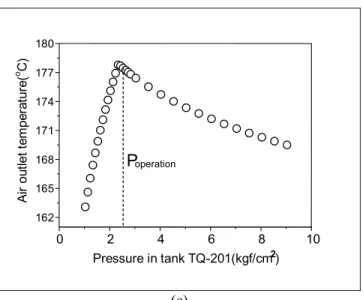
operation. Keeping all other parameters constant, simulations were conducted varying this pressure from 1.0 to 9.0 kgf/cm2. The results for air outlet temperature are presented in Figure 3.
In EX-101, the air temperature increases continuously as the pressure in tank TQ-101 increases. For the other two units, a steep initial rise in temperature is verified up to a pressure of about 2.0 kgf/cm2, where a maximum point is reached. From then on, any further increase in pressure leads to a decline in air outlet temperature. This behaviour points to the existence of an optimal operating value for the pressure in the tank, with which a minimum steam consumption for a given outlet temperature would be associated. In the simulations conducted, the highest temperature for the drying air was
obtained for P101 = 2.33 kgf/cm2, a value similar to
the plant’s normal operating condition (P101 = 2.53
kgf/cm2), indicating, thereby, that the air heating system is actually working quite close to the region of minimum steam consumption.
As all other operating parameters are fixed, the total flow rate of condensate that is fed into TQ-101 is approximately constant, so the higher the pressure in the tank, the higher the flow rate of liquid water pumped as heating fluid into EX-101. This increment in the feed flow rate results in a higher heat-transfer coefficient on the tube side, and, since the resistance associated with convection on the tube side is significant, an increase in the U value is observed.
The flow rate of heating steam fed into EX-102, and consequently the available latent heat, decreases when P101 is raised (Figure 4). On the other hand, the
amount of heat that can actually be transferred within this unit increases with P101 due to the increment in
the LMTD value caused by the higher steam temperature, which is high enough to compensate for the rise in air inlet temperature. Initially, when P101 <
2.33 kgf/cm2, the amount of available latent heat remains greater than the amount of transferable energy, so the reduction in the former does not prevent the latter from increasing and the quality of the water stream that leaves EX-102 falls accordingly, as shown in Figure 4. For higher operating pressures in TQ-101, the opposite situation is verified and the amount of available latent heat becomes smaller than the amount of transferable heat, or in other words, the steam is totally
condensed without using all of the available heat-transfer area. Due to the declining steam feed flow rate, the amount of energy actually transferred, and consequently the air outlet temperature, falls progressively.
The results obtained for EX-103/4 are directly related to what happens in EX-102. In EX-103/4, in view of the fact that the steam flow rate is a specified parameter, the available latent heat is fixed. For the P101 range studied, the amount of energy that can be
transferred within the equipment is slightly larger than that available. Therefore, no change is verified for the amount of heat actually transferred in the equipment and the outlet temperature varies with the inlet temperature, an outcome which supports the strong resemblance between the temperature curves in Figures 3(b) and 3(c).
0 2 4 6 8 10
40 45 50 55 60 65
Poperation
A
ir
ou
tl
et
t
e
m
pe
ra
tur
e
(
o C)
Pressure in tank TQ-201 (kgf/cm2)
(a)
0 2 4 6 8 10
69 72 75 78 81 84 87
Poperation
A
ir
ou
tl
et
t
e
m
pe
ra
tur
e
(
o C)
Pressure in tank TQ-201 (kgf/cm2)
0 2 4 6 8 10
162 165 168 171 174 177 180
Poperation
A
ir
ou
tl
et
t
e
m
pe
ra
tu
re
(
o C)
Pressure in tank TQ-201(kgf/cm2)
(c)
Figure 3: Effect of operating pressure in TQ-101 on the air outlet temperature: (a) – EX-101; (b) – EX-102; (c) – EX-103/4.
0 2 4 6 8 10
200 300 400 500 600 700 800
Poperation
Condensate Feed steam
Flo
w
r
a
te (
k
g
/h
)
Pressure in tank TQ-101 (kgf/cm)2
Figure 4: Variation in steam and condensate flow rate in EX-102 as a function of the operating pressure in TQ-101.
CONCLUSIONS ACKNOWLEDGEMENTS
The integration of calculation codes developed in this work into the ASPEN Plus shell enabled the elaboration of a simulation model for the whole drying-air heating system of a powdered milk plant. The adequacy of this model was proven by means of a comparison between simulation results and operating data.
The authors would like to acknowledge the financial support provided by FAPEMIG for the development of this work, as well as the authorisation conceded by Embaré Indústrias Alimentíciais S. A. for a study of part of their industrial plant.
The model was used as a means of conducting a sensitivity analysis of this system for one of its operating parameters. The existence of an optimal value for this variable, associated with a minimum consumption of steam, was confirmed.
NOMENCLATURE
A area, m2
B fin width, m c cold fluid
C fin length, m ext external side of the tube
Cp heat capacity, J kg-1 fin fins
D1 minor axis of the elliptical tube, m h hot fluid
D2 major axis of the elliptical tube, m in inlet condition
int internal side of the tube Deq equivalent diameter, m
l liquid f LMTD correction factor, -
F mass flow rate, kg s-1 out outlet condition
f1 function defined by equation 17, m s saturation
f2 function defined by equation 18, m sl shell
g gravitational acceleration, m s-2 T total surface of finned tubes
h heat-transfer coefficient, W m-2 K-1 tb tubes
v vapour I1 modified Bessel function of the first kind
of order one, - w wall
Io modified Bessel function of the first kind
of order zero, - Greek Symbols
k thermal conductivity, W m-1 K-1
D,E parametric coordinates of an ellipse’s evolute, m
kn slope of an ellipse’s curvature radius, -
K1 modified Bessel function of the second
kind of order one, - G condensate film thickness,m
Ko modified Bessel function of the second
kind of order zero,
-H eccentricity of an ellipse, -
J latent heat of vaporisation, J kg-1
L tube length, m K fin efficiency, -
LMTD logarithmic mean temperature difference,
K K mean fin efficiency, -
P viscosity, Pa s m parameter given by equation 9, m-1
U density, kg m-3 nfin number of fins per tube length, m-1
\ tube inclination, rad ntb total number of tubes in the exchanger, -
ntransv number of tubes in the bundle transverse
direction, -
Nu Nusselt number, h Deq k -1
, -
REFERENCES
P101 operating pressure in tank TQ-101, Pa
Pr Prandtl number, CpP k-1, - Bowman, R.A., Mueller, A.C. and Nagle, W.M.,
Mean Temperature Difference in Design, Transactions of the American Society of Mechanical Engineers, 62, 283 (1940).
Q heat transfer rate, W
rc parameter given by equation 16, m
Re Reynolds number,U v DeqP-1, -
Boyce, W.E. and Di Prima, R.C., Equações Diferenciais Elementares e Problemas de Valores de Contorno. Guanabara Koogan, Rio de Janeiro (1994).
ro curvature radius, m
S1 transverse bundle pitch, m
S2 longitudinal bundle pitch, m
Caric, M., Concentrated and Dried Dairy Products. In: Hui, Y.H. (Ed.), Dairy Science and Technology Handbook vol. 2. VCH, New York (1994).
t fin thickness, m T temperature, K
U overall heat-transfer coefficient, W m-2 K-1 v fluid velocity, m s-1
Douglas, P.L. and Young, B.E., Modelling and Simulation of an AFBC Steam Heating Plant Using ASPEN/SP, Fuel, 70, No. 2, 145 (1991). x, y parametric coordinates, m
Z dimensionless condensate film thickness, -
Evans, L.B., Boston, J.F., Britt, H.I., Gallier, P.W., Gupta, P.K., Joseph, B., Mahalec, V., Seider,
Motard, R.L., Shacham, M. and Rosen, E.M., Steady-state Chemical Process Simulation, AIChE Journal, 21, No. 3, 417 (1975).
W.D. and Yagi, H., ASPEN: An Advanced System for Process Engineering, Computers and Chemical Engineering, 3, 319 (1979).
O’Donnell, C.P., McKenna, B.M., Herlihy, N., Drying of Skim Milk: Opportunities for Reduced Steam, Drying Technology, 14, No. 3-4, 513 (1996).
Fieg, G.P. and Roetzel, W., Calculation of Laminar Film Condensation in/on Inclined Elliptical Tubes, International Journal of Heat and Mass Transfer, 37, No. 4, 619 (1994).
Ong’iro, A., Ugursal, I., Al Tawee, M.A. and Lajeunesse, G., Thermodynamic Simulation and Evaluation of a Steam CHP Plant using ASPEN Plus, Applied Thermal Engineering, 16, No. 3, 263 (1996).
Hashizume, K., Heat Transfer and Pressure Drop across Finned Tubes. In: Cheremisinoff, N.P. (Ed.), Handbook of Heat and Mass Transfer vol. 1 - Heat Transfer Operations. Gulf, Houston (1986).
Ilgarubis, V.A.S.; Ulinskas, R.V. and Butkus, A.V., Hydraulic Drag and Average Heat Transfer Coefficients of Compact Bundles of Elliptical Finned Tubes, Heat Transfer-Soviet Research, 20, No. 1, 12 (1988).
Rachid, R. Jr. and Caño Andrade, M.H., Steady-state Simulation of the Sour Water Treatment Plant of a Brazilian Refinery, Actas del 5o Congreso Interamericano de Computación Aplicada a la Industria de Procesos – CAIP 2001. Campos do Jordão, 187 (2001).
Incropera, F.P. and DeWitt, D.P., Introduction to Heat Transfer. John Wiley & Sons, New York (1996).
Ribeiro, C.P. Jr. Modelling of Plate Heat-transfer Systems and Simulation of a Brazilian Powdered Milk Plant, Master’s thesis, Federal University of Minas Gerais, Belo Horizonte (2001).
Jansen, L.A. and Elgersma, R.H.C., Direct Heating of Drying Air with Natural Gas in the Preparation of Milk Powder, Journal of the Society of Dairy Technology, 38, No. 4, 134 (1985).
Ribeiro, C.P. Jr. and Caño Andrade, M.H., Performance Analysis of the Milk Concentrating System from a Brazilian Milk Powder Plant, Journal of Food Process Engineering, 26, No. 2, 181 (2003).
Kelly, P.M., Gray, J.I., Slattery, J., Direct Low-NOX Gas Combustion Heating of a Spray Dryer during Milk Powder Manufacture, , Journal of the Society of Dairy Technology, 42, No. 1, 14 (1989).
Schuck, P., Spray Drying of Dairy Products: State of the Art, Lait, 82, No. 4, 375 (2002).
Knipschildt, M.E. and Andersen, G.G., Drying of Milk and Milk Products. In: Robinson, R.K. (Ed.), Modern Dairy Technology vol.1. Chapman & Hall, London (1994).
Simmons, G.F., Cálculo com Geometria Analítica, vol. 2. McGraw-Hill, São Paulo (1987).
Suyi, H. and Shizhou, P., Convection and Heat Transfer of Elliptical Tubes, Heat and Mass Transfer, 30, No. 6, 411 (1995).
Marto, P.J., Heat Transfer in Condensation. In: Kakaç, S. (Ed.), Boilers, Evaporators and Condensers. John Wiley & Sons, New York (1991).
Varnam, A.H. and Sutherland, J.P., Milk and Milk Products. Chapman & Hall, London (1994). Velic, D., Bilic, M., Tomas, S. and Planinic, M.,
Simulation, Calculation and Possibilities of Energy Saving in Spray Drying Process, Applied Thermal Engineering, 23, 2119 (2003).