Abstract
State-of-the art studies of impact crushing circular stepped tube (inversion tube) introduce various approaches to improve the energy absorption capacities. Adding external longitudinal stiffen-ers on the circular stepped tubes is a new approach that have a great effect and interest. In the current study, finite element anal-ysis using (LS-DYNA/WORKBENCH ANSYS) is performed on a series of numerical models of aluminum circular stepped tubes that are externally stiffened by a constant number of longitudinal stiff-eners distributed around the cross section of the circular stepped tube. The numerical models are implemented under an axial im-pact crushing scenario. Furthermore, a new improved formula for prediction of steady inversion load is proposed. The theoretical predictions are found to be in good agreement with the numerical results with an error within 12%. A comparative study is conduct-ed to compare the energy absorption characteristics and inversion mechanism between the newly proposed tubes and the convention-al stepped tube. The results showed that addition of externconvention-al lon-gitudinal stiffeners on circular stepped tubes could imply greatest improvement for the energy absorption up to 104%, specific energy absorption capability (energy absorption per unit mass) up to 54.9%, the crush force efficiency up to 40.3% and increase the inversion stroke length in comparison with the unstiffened circular stepped tubes. A newfound role of external longitudinal stiffeners added to the stepped tubes that controls the inversion and defor-mation mechanism is presented.
Keywords
Stepped Tube; Stiffeners; circular; energy absorption; impact.
A New Configuration of Circular Stepped Tubes
Reinforced with External Stiffeners to Improve Energy
Absorption Characteristics Under Axial Impact
M.S. Zahran a
P. Xue a M.S. Esa a
M.M. Abdelwahab b Guoxing Lu c
a School of Aeronautics, Northwestern
Polytechnical University, Xi’an, 710072, China.
[email protected], [email protected],
b Civil Engineering Department, Military
Technical College,Cairo, Egypt, [email protected]
c Faculty of Science, Engineering and
Technology, Swinburne University of Technology, Hawthorn, VIC 3122, [email protected]
http://dx.doi.org/10.1590/1679-78253231
1 INTRODUCTION
Energy absorbers are widely used in the various engineering field, on things such as car bumpers, subfloors of aircraft, train buffers, marine structures, machinery, and bottom of the stepped pool (Lu and Yu, 2003;Dundulis et al., 2015). The main goal of the energy absorbers is to protect the engineering systems from serious damage or prevent occupant fatalities and minimize the severity of injuries in the event of crash impacts. The specific energy absorption (SEA, energy absorption per unit mass) is one of the most extensive aspects to evaluate the efficiency of the energy absorbers, with addition of other characteristics like mean crushing load, stroke crushing length, and stroke efficiency (Lu and Yu, 2003;Olabi et al., 2007).
Thin-walled tubes can absorb impact energy through different ways, such as friction, fracture, shear, bending, tension, torsion, metal cutting, plastic deformation, splitting, stiffeners, extrusion and fluid flow(Jones, 2011). They can be produced with different geometric shapes such as circular, conical, square, taper, octagonal, hexagonal, frusta, S-shaped. Amongst them, thin -walled circular tubes are the most frequently used in energy absorbers due to their high strength, high stiffness, low weight, inexpensive, versatile, easy in manufacturing, excellent behaviors on energy absorption characteristics and load carrying capacity (Alghamdi, 2001;Jones, 2011).
Most earlier research focused on axial compression loading of the tubes. The crush takes place progressively, and consequently the energy can be dissipated with high energy absorption, long stroke and crushing stability along a large plastic deformation process (Reid, 1993) . The thin-walled circular tubes under axial impact loading could absorb the energy with different mechanisms such as splitting (Niknejad et al., 2013), extrusion (Galib et al., 2006), expansion (Salehghaffari et al., 2010), trigger (Huang and Wang, 2010), inversion (Guist and Marble, 1966;Rosa et al., 2003;Luo et al., 2007;Gupta, 2014;andQiu et al., 2014), stiffeners (lateral or longitudinal )(Zhang and Suzuki, 2007), metal cutting (Jin and Altenhof, 2011). During the progressive crushing under axial compres-sion, different types of deformation modes such as an axisymmetric (concertina) mode, non-symmetric (diamond) mode, mixed mode or global Euler buckling mode, could happen depending on the geometric parameters of the tube (length, diameter and thickness),material properties and boundary conditions (Andrews et al., 1983;Abramowicz and Jones, 1984). Under special boundary conditions, the thin-walled tubes can deform to a special mode called inversion mode. In this defor-mation mode, the tube can be called double walled tube, inversion tube, invert-tube or inverbuck-tube. The inversion process can be used to absorb high energy due to its constant inversion load during the deformation process resulting in an ideal long stable crush load–stroke curve. The inver-sion tubes have extensive applications, such as lift shaft emergency arrestors, buffer element for rail vehicles, pier fenders, and air drop packages (Jones, 2011). The thin-walled tube can be inverted inside-out or outside-in. Basically, there are two ways to produce the inversion tube: the first one is the free inversion, and the second is the inversion with a die. Inversions with a die are mainly achieved by axially compressing the tube onto a designed die. The free inversion needs a suitable fixture during axial compression, and is only feasible for ductile material (Al-Hassani et al., 1972;Reddy, 1992).
well with their analytical predictions. Reddy(1992) extended Guist and Marble's model by including strain hardening of the material. Then, Colokoglu and Reddy(1996)further investigated the effects of strain rate and inertia during the dynamic free inversion process. Furthermore, Qiu et al.(2014)modified Reddy's model to predict the knuckle radius and the steady inversion load during the external inversion process for aluminum circular tubes. Tomesani(1997)presented a modified way to conducted outside-in inversion process by using tension load at the inner wall instead of compression at the outer wall. Zhang et al.(2009)introduced a new design of inversion tube based on free inversion mechanism to improve the energy absorption so as to overcome the drawbacks in the traditional types of inversion tubes. The new design constituted by two tubes, the upper tube (cyl-inder) inverted the lower tube (cylinder or tapered tube), the two tubes connected by annular zone and the lower tube worked as a built in elastic die.
The circular stepped tubes can be considered as a type of free inversion technique which has been considered preferable for energy absorbers, because it provides a desirable stable crush load– displacement curve and absorbs a large amount of impact energy under axial loading(Chen and Yang, 2012;Higuchi et al., 2014). In addition, it is observed that using stiffeners (externally or in-ternally- axial or lateral) as a way for improving the energy absorption characteristics, enhancing the stability, modifying the plastic collapse behavior and adjusting the deformation mechanisms of the thin walled tubes. For examples,Zhang and Suzuki(2007)studied numerically on the crushing collapse of a stiffened square tube and showed that the longitudinal and transverse stiffeners had a great effect on the mean crushing load. Jones and Birch (1990) modified the axial plastic collapse behavior by adding stringer stiffening on the inside or outside surfaces of the tubes. Red-dy(1980)discussed the effect of stiffeners size of stiffened shell on the critical stress, stiffeners eccentricity and the number of stiffeners. Pedersen(1973) analyzed the initial post buckling be-havior of both unstiffened and outside ring stiffened circular cylindrical shells under axial compres-sion. Adachi et al. (2008) investigated experimentally and theoretically the effect of stiff ribs for several different cylinders and this study showed that the ribs can improve the energy absorption characteristics and adjust formation of a structure. (Liu et al., 2015)introduced a way for improving energy absorption property by adding bulkheads in the columns, also presented that the bulkheads can change the deformation mode from an expansion-contraction mode to a progressive mode. Moreover, the influence of ring-stiffened circular tubes have been studied (Ross et al., 1994;Salehghaffari et al., 2011) and the internal stiffeners (called multi-cell sections) have been ap-plied in engineering application (Nia and Parsapour, 2014;Tran et al., 2014;andZhang and Zhang, 2014).
study is conducted to compare the energy absorption characteristics and inversion mechanisms be-tween the newly proposed stepped tubes and the conventional stepped tube. Moreover, the ratio of the stiffener width and the length of step connection is the effective parameter for the inversion process to affect the inversion deformation, stroke length, inversion stroke length, absorbed energy and the specific energy absorption. The study focuses on the variation of the external stiffener width, its influence on the energy absorption characteristics and the inversion mechanism scenario.
2 STRUCTURAL CONFIGURATION
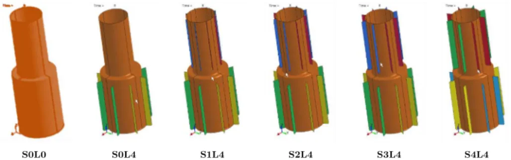
A new configuration of circular stepped tube named as stiffened circular stepped tube is proposed. As no previous work in this configuration, there is no limitations to construct this configuration with respect to the number of stiffeners (N) and width of stiffeners. In the present work, the stepped tube is made of Aluminum alloy AA6060-T4, double cylinders R1 and R2 are the radius of the small cylinder and the large cylinder, respectively. The two cylinders are connected by a flat connection with length (CL), as shown in Figure 1. Eight stiffeners(N=8) are distributed around the cross section of the small tube and the large tube. The ratio of the stiffener width of small tube or large tube (SSW or LSW) to the connection length (CL) is abbreviated as (Š)and can be ob-tained from following equations:
S
SSW CL
Š (1)
where ŠS and SSW are the small tube stiffener ratio and small tube stiffener width respectively.
L
LSW CL
Š (2)
where ŠL and LSW are the large tube stiffener ratio and large tube stiffener width, respectively.
In order to achieve the inversion process, it is assumed that the ratio (Š) is constrained by the length of connection (CL) hence it cannot exceed this length otherwise the inversion process is im-possible. Twenty-five configurations are conducted in order to investigate the energy absorption characteristics and the crushing behavior of the newly proposed design. All configurations have an identical wall thickness (t=1.5 mm), tube length (L1=100mm, L2=100mm), tube radius (R1=25mm, R2=35mm) and CL=10mm. All stiffeners have rectangular geometric shape with the same height (SSH=LSH=90mm) and thickness (t=1.5 mm), as shown in Figure 1. According to the literature reviews, the stiffened stepped tube can be manufactured in the practice through two techniques. The first technique is using “Friction stir welding” which is mainly used to overcomes many of the problems associated with traditional joining techniques. Several investigations studied the effect of the welding on the performance of the energy absorber. For example,Dundulis et al.(2015) studied the influence of the weld on vertical buckling of the crash absorber under impact loading. Their results showed that the longitudinal weld does not influence a noticeable adverse effect on the shock absorber operation, the tube deforms smoothly similarly to the one without weld and can withstand similar loads. The other technique called as “hydroforming of multi-curved hol-low parts” can be used to manufacture of the cylindrical element provided with ribs and stringers.
3 THEORETICAL ANALYSIS
3.1 Inversion Conditions
The stiffener’s role in the inversion process of circular stepped tubes can be predicted through a simple approach as follows:
Assuming an axial force F applies on a circular stepped tube with double cylinders (R1 and R2), they are connected by a flat connection with length (CL) as shown in Figure 1. According to the theory of mechanics, it is evident that the normal stress will be directly decreased if the second moment of inertia for the tube wall (Iw) is increased to be the second moment of inertia for the tube wall plus the second moment of inertia for the stiffeners (Iw+s). Starting from that concept, adding external longitudinal stiffeners to the small tube and the large tube is assumed to show the influ-ence on decreasing the curling normal stress so increasing the tubes resistance and energy absorp-tion of the stepped tube. The inversion process after adding the stiffeners can be classified to differ-ent kinds of inversion mechanisms as listed in Table 1.
Inversion Conditions Mechanism Name Description
I(w+s) small tube < I(w+s)large tube Regular Inversion
The small tube inverts inside the large tube which means that the large tube
acts as a die to the small tube.
I(w+s)small tube >I(w+s)large tube Irregular Inversion
The large tube deforms inside the small tube, which means that the small tube
acts as a die to the large tube.
I(w+s)small tube = I(w+s)large tube Simultaneous Inversion The large tube deforms at the same
time with the small tube.
3.2 Simplified Theory of (Guist and Marble, 1966)
The mean crushing force of circular tubes based on external free inversion process was investigated by a few studies (Guist and Marble 1966;Reddy, 1992;Colokoglu and Reddy, 1996;Qiu et al., 2014;andQiu et al., 2016). Firstly, Guist and Marble(1966) proposed a simplified theory to predict the steady-state inversion load of free inversion tube. Based on their theory some basic assumptions were assumed as follows: the material is perfectly plastic; the inversion process occurs at constant load and the work done by the inversion load is balanced to the internal plastic work (internal plas-tic dissipation). Then, Guist and Marble's steady inversion load can be predicted by:
m o
b t
F 2 σ rt
r 4b
(3)
where r is the radius of the upper tube, t is the thickness of the tube, b is the knuckle radius and σ0 is the dynamic flow stress.
In order to minimize the inversion load, it is assumed that the value of the knuckle radius is b = rt/ 2. In this theory, the energy absorbed in three separate processes bending, extension and bending. Moreover, the bending and extension processes dissipate the equal amount of energy. Their experimental and theoretical results showed that the steady inversion load formula provided an error within 15% (Guist and Marble, 1966).
3.3 New Improved Formula for the Steady Inversion Load of Stiffened Circular Stepped Tube
A simple method to predict the steady inversion load for stiffened stepped tube is using an equiva-lent thickness concept, which means that the stiffened tube is replaced by an unstiffened tube with the equivalent plate thickness. Numerous investigations were done to validate the equivalent plate thickness method for different types of structural members. Zhang and Suzuki(2007) introduced a new formula for the equivalent thickness of the longitudinal stiffeners and the mean crushing load. Zhang and Suzuki's formula validated by numerical and experimental work and it was found that the prediction of the mean crushing load is in good agreement with the experimental data. The equivalent thickness of the longitudinal stiffeners is given by(Zhang and Suzuki, 2007):
1 eq
NA
t t k
2 r
(4)
where teq is the equivalent thickness of stepped tube, t is the initial thickness of stepped tube, A1 is the sectional area of longitudinal stiffeners, N is the number of longitudinal stiffeners, r is the radius of the tube and K is a coefficient accounting for the influence of the longitudinal stiffeners. Accord-ing to Zhang and Suzuki's experimental data, K is set to be 1.05.
eq
ms o eq
t b F 2 σ rt
r 4b
(5)
where Fms is the static steady inversion load of stiffened circular stepped tube, σo is the dynamic flow stress, r is the radius of the upper tube, b is the knuckle radius and teq is the equivalent thick-ness of the stepped tube.
In the present investigation, the numerical results are compared with the new improved formula results in order to ensure the accuracy of the new improved formula. The application of dynamic load on structures of some materials makes them deform rapidly, resulting in high strain rates in the struc-ture. Thus, the plastic flow of material sensitive to the value of the strain rate is known as material strain rate sensitivity(Chen et al., 2009;Simhachalam et al., 2014). A lot of research has been done to calculate the strain rate sensitivity of the aluminum circular tube under impact loading. Recently, the dynamic factor range of aluminum alloys under different strain rates is conducted by Simhachalam et al.(2014), the dynamic impact factor of aluminum alloys for velocity 10 m/s comes out to be from 1.1 to 1.13 ,thus the theoretical dynamic steady inversion load (Fmd) for stiffened stepped tube varies from the range 1.1Fms to 1.13Fms . From the theoretical analysis, it is found that the thickness of the tube is an effective parameter on the steady inversion load and the inversion process then the follow-ing models are conducted with different equivalent thickness by addfollow-ing external longitudinal stiffeners to the large and the small tubes of the stepped tube with various values of width.
4 FINITE ELEMENT MODELLING
4.1 Numerical Program and Description of Numerical Groups
The numerical program includes five groups (Si, i = 0,1,2,3,4), as shown in Table 2. Each group is consisting of five numerical models and the difference between models is the ratio of the stiffener width (ŠS, ŠL). All numerical models are also compared with unstiffened stepped tube (S0L0). Such as, the first group S0 consists of five numerical models, i.e. S0L0, S0L1, S0L2, S0L3 and S0L4. The abbreviation of “S” and “L” are used to identify the small cylinder in the stepped tube and the large cylinder in the stepped tube, respectively. The abbreviation of “0” is used to identify the unstiffened stepped tube, the abbreviation of “1”, “2”, “3” and “4” are used to identify the stiffened stepped tube with ratio (ŠS or ŠL) = 0.25, 0.5, 0.75 and 1.0 respectively, that ratio can be calculated from Equa-tion (1) and EquaEqua-tion (2). In other words, the abbreviaEqua-tion of “1”, “2”, “3” and “4” means that (SSW or LSW) = 2.5 mm, 5 mm, 7.5 mm, 10 mm, respectively, as shown in Figure 2 and Table 2.
S0L0 S0L4 S1L4 S2L4 S3L4 S4L4
Group
name Description of models
S0L0 S0L1 S0L2 S0L3 S0L4
1st Group (S0) unstiffened stepped tube. unstiffened small tube and stiffened
large tube with ratio ŠL=0.25
unstiffened small tube and stiffened
large tube with ratio ŠL=0.5
unstiffened small tube and stiffened large tube with
ratio ŠL=0.75
unstiffened small tube and stiffened
large tube with ratio ŠL=1.0
2nd Group
(S1)
S1L0 S1L1 S1L2 S1L3 S1L4
stiffened small tube with ratio ŠS=0.25 and
unstiffened large tube
stiffened small tube with ratio ŠS=0.25 and
stiffened large tube with ratio
ŠL=0.25
stiffened small tube with ratio ŠS=0.25 and
stiffened large tube with ratio
ŠL=0.5
stiffened small tube with ratio ŠS=0.25 and
stiffened large tube with ratio
ŠL=0.75
stiffened small tube with ratio ŠS=0.25 and
stiffened large tube with ratio
ŠL=1.0
3rd Group
(S2)
S2L0 S2L1 S2L2 S2L3 S2L4
stiffened small tube with ratio ŠS=0.5 and
un-stiffened large tube
stiffened small tube with ratio ŠS=0.5 and
stiff-ened large tube with ratio
ŠL=0.25
stiffened small tube with ratio ŠS=0.5 and
stiff-ened large tube with ratio ŠL=0.5
stiffened small tube with ratio ŠS=0.5 and
stiff-ened large tube with ratio
ŠL=0.75
stiffened small tube with ratio ŠS=0.5 and
stiff-ened large tube with ratio ŠL=1.0
4th Group
(S3)
S3L0 S3L1 S3L2 S3L3 S3L4
stiffened small tube with ratio ŠS=0.75 and
unstiffened large tube
stiffened small tube with ratio ŠS=0.75 and
stiffened large tube with ratio
ŠL=0.25
stiffened small tube with ratio ŠS=0.75 and
stiffened large tube with ratio
ŠL=0.5
stiffened small tube with ratio ŠS=0.75 and
stiffened large tube with ratio
ŠL=0.75
stiffened small tube with ratio ŠS=0.75 and
stiffened large tube with ratio
ŠL=1.0
5th Group
(S4)
S4L0 S4L1 S4L2 S4L3 S4L4
stiffened small tube with ratio ŠS=1.0 and
un-stiffened large tube
stiffened small tube with ratio ŠS=1.0 and
stiff-ened large tube with ratio
ŠL=0.25
stiffened small tube with ratio ŠS=1.0 and
stiff-ened large tube with ratio ŠL=0.5
stiffened small tube with ratio ŠS=1.0 and
stiff-ened large tube with ratio
ŠL=0.75
stiffened small tube with ratio ŠS=1.0 and
stiff-ened large tube with ratio ŠL=1.0
Table 2: Description of numerical groups.
4.2 Description of Finite Element Modeling
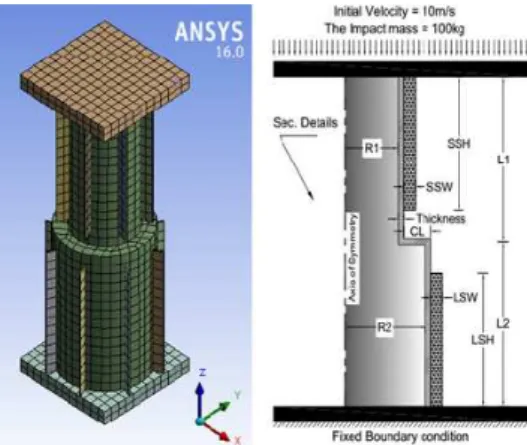
found to be sufficient to simulate the tubes with good accuracy. It may be noted that the coarse meshing is used to model the plates, as these are defined as rigid parts. The material model MAT_123 “MAT_MODIFIED_PIECEWISE_LINEAR_PLASTICITY” in LS-DYNA is adopted to model aluminum alloy tubes. The stepped tube is placed between two rigid plates modelled as lower and upper supports. The rigid body with initial impact velocity 10 m/s strikes the circular stepped tube axially and the mass of the rigid body is 100 kg, as shown in Figure 3. The upper plate is con-strained in all degrees of freedom except for the movement in the direction of the axis of tubes. The lower plate is constrained in all degree of freedom. Two different types of contacts are used to simu-late the interaction between surfaces. The first is used to model the interfaces between the wall of the tube and the rigid plates by using “AUTOMATIC_SURFACE_TO_SURFACE”. The second is adopted to avoid the interpenetration of the tubes wall during fold formation by using “AUTOMAT-IC_SINGLE_SURFACE”. The contacts between all surfaces are described as “FRICTIONAL”, with dynamic coefficient taken as 0.25. Based on Dundulis et al.(2015)study, The mesh contacts between the stepped tube and the longitudinal stiffeners are described as “NODE MERGE”.
The circular stepped tubes and stiffeners are made of aluminum alloy AA6060-T4 with the fol-lowing mechanical properties(Santosa et al., 2000) ,as listed in Table 3.
Material Young’s Modulus (E)
initial yield stress (ϭy)
ultimate stress (ϭu)
Poisson’s ratio (ν)
power law exponent (n)
Density ( )
GPa MPa MPa kg/m3
AA6060-T4 68.2 80 173 0.3 0.23 2770
Table 3: Mechanical properties of aluminum alloy AA6060-T4 (Santosa et al., 2000).
Moreover, σo =126.5 MPa is the dynamic flow stress, and is taken as the average of tensile yield stress and ultimate tensile stress (Zhang and Zhang, 2013). Aluminum alloy AA6060-T4 exhibit only slight sensitivity to the strain rate, and could be modelled as rate-insensitive with good accura-cy. Furthermore, the use of aluminum in energy absorption systems can decrease the weight of the energy absorber with a ratio of 25% compared with traditional steel energy structure, also, the rup-ture strain of steel is larger than the aluminum alloy which is undesired in the inversion or defor-mation process (Zarei and Kröger, 2006;Chen et al., 2009).
5 PERFORMANCE INDEX FOR ENERGY ABSORBER
There are many indexes that have been presented to assess the performance and efficiency of the energy absorber (Alghamdi, 2001;Lu and Yu, 2003;andJones, 2010). In the current investigation, the desired parameters, which used for comparison and could be obtained from load-displacement curve, as follows.
5.1 Total Absorbed Energy (EA)
The total absorbed energy during axial crushing is calculated by the area under load–displacement curve from the following equation:
EA
Fdδ (6)where F and δ are crushing load, and crushing distance, respectively.
5.2 Specific Energy Absorption (SEA)
SEA is common criterion for comparing the energy absorbers, which is defined as the ratio of the energy absorbed by a structure to its mass (m) and is given by:
t
Fdδ SEA
m
(7)where mt is total mass of the structure.
5.3 Stroke Length (SL)
Stroke length is the deformable distance of structure along the loading direction, which means the displacement before starting the densification zone on the load- displacement curve.
5.4 Crush Force Efficiency (CFE)
CFE is defined as the ratio of the mean crushing force (Fm) to the peak force (Fp) where the mean crushing force (Fm) is defined by dividing the total energy absorbed (EA) by the stroke crushing distance (SL). CFE can be obtained from the following equation:
m
P P
F EA
CFE
F F SL
(8)
where Fm and FP are mean crushing force and peak crushing force, respectively.
5.5 Inversion Stroke Length (ISL)
6 NUMERICAL RESULTS AND DISCUSSIONS
In the present investigation, five groups with different configurations (S0, S1, S2, S3, and S4) are proposed. Moreover, a comparative study carried out to compare the energy absorption indexes and inversion mechanism of all numerical models, in order to evaluate the crushing capability of all con-figurations considered in the current work.
6.1 Influence of External Longitudinal Stiffeners on Inversion Mechanisms of Stepped Tubes
Adding the external longitudinal stiffeners can make the inversion process of the stepped tubes with different kinds of inversion mechanisms. The effect of external longitudinal stiffeners on inversion mechanisms is shown in Figures 4-6 and Table 4. These figures show the progressive deformation patterns of models under axial impact.
a) Progressive deformation pattern of model S0L0 b) Progressive deformation pattern of model S0L1
Figure 4: Examples of regular inversion mechanism.
a) Progressive deformation pattern of model S3L0 b) Progressive deformation pattern of model S4L0
a) Progressive deformation pattern of model S2L3 b) Progressive deformation pattern of model S3L2
Figure 6: Examples of simultaneous inversion mechanism.
Mechanism Name Model ID
Regular Inversion S0L1, S0L2, S0L3, S0L4, S1L3, S1L4 Irregular Inversion S2L0, S3L0, S3L1, S4L0
Simultaneous Inversion S1L0, S1L1, S1L2, S2L1, S2L2, S2L3, S2L4, S3L2, S3L3, S3L4, S4L1, S4L2, S4L3, S4L4
Table 4: Inversion mechanisms of all numerical models.
During the inversion process, three different inversion mechanisms can be observed and named as regular inversion, irregular inversion, and simultaneous inversion, as shown in Table 4 and Fig-ures 4-6. The regular inversion means that the small tube inverts inside the large tube. This hap-pens due to increase in the stiffness of the large tube by adding the stiffeners, hence the stiffness of the smaller tube is much lower than the stiffness of the large tube as shown in Figure 4. The irregu-lar inversion means that the irregu-large tube deforms inside the small tube, which means that the small tube acts as a die to the large tube as shown in Figure 5. This behavior may not happen in the regular free inversion. The simultaneous inversion means that the large tube deforms at the same time with the small tube as shown in Figure 6. The deformation happens simultaneously as a result of the increase in the stiffness of the small tube with the addition of stiffeners. The stiffness of the smaller tube, in this case, is almost equivalent to the stiffness of the large tube. Figures 4‐6 show
the progressive deformation patterns of numerical models (S0L0‐S0L1‐S3L0S4L0‐S3L2‐S2L3)
longitudinal stiffeners to the small tube and the large tube show great influence on the inversion and deformation mechanism of the stepped tube.
6.2 Comparing Energy Absorption Indexes
The energy absorption indexes could be obtained from the force-displacement curve after perform-ing the crash simulations. These indexes are calculated usperform-ing the equations listed in the Section 5. Figures 7-11 show the force-displacement curves for the models, which have the best performance and the highest energy absorption indexes in each group (highlighted in Table 5.) in comparison with the unstiffened stepped tube. Table 5 presents the finite element results for the energy absorp-tions indexes and the theoretical predicabsorp-tions of all numerical models considered in the current inves-tigation.
Figure 7: Load-displacement curves of model S0L2 in-group S0 and S0L0.
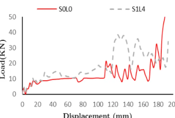
Figure 8: Load-displacement curves of model S1L4 in-group S1 and S0L0.
Figure 9: Load-displacement curves of model S2L1 in-group S2 and S0L0.
Numerical simulations Theoretical predictions (Eq. 5) Group name Model
ID Mass EA SEA
Increase
SEA ISL SL Fm FP
CF
E Fmd Error
(Kg) (KJ) (KJ) (%) (mm) (mm) (KN) (KN) (%) (KN) (%)
1st
Group S0
S0L0 0.16 1.43 8.72 0.00 108 183 7.83 32.8 23.8 8.25 5.09 S0L1 0.17 1.60 9.31 6.73 107 176 9.09 34.4 26.4 8.85 -2.69 S0L2 0.18 1.83 10.2 16.98 107 179 10.2 37.7 27.1 9.46 -7.96 S0L3 0.19 1.72 9.19 5.33 107 179 9.59 34.9 27.4 10.1 5.00 S0L4 0.19 1.71 8.78 0.69 107 172 9.92 27.5 36.1 10.7 7.55
2nd Group
S1
S1L0 0.17 1.66 9.66 10.67 129 163 10.2 25.4 40. 9.10 11.8 S1L1 0.18 1.73 9.68 10.90 129 175 9.91 28.6 34.6 9.71 -2.01 S1L2 0.19 1.91 10.2 17.04 121 181 10.5 34.4 30.6 10.4 -1.83 S1L3 0.19 2.10 10.8 23.84 117 186 11.2 34.9 32.3 10.9 -2.67 S1L4 0.20 2.23 11.0 26.63 120 186 11.9 37.2 32.2 11.6 -2.88
3rd Group
S2
S2L0 0.18 1.98 11.1 26.70 111 185 10.7 27.7 38.6 9.96 -7.47 S2L1 0.19 2.21 11.8 35.76 118 189 11.7 26.5 44.1 10.6 10.3 S2L2 0.19 1.93 9.93 13.87 125 188 10.2 39.8 25.7 11.2 8.78 S2L3 0.20 2.23 11.1 26.45 130 178 12.5 24.8 50.4 11.9 -4.95 S2L4 0.21 2.30 11.0 26.12 138 185 12.4 29.8 41.7 12.5 1.14
4th
Group S3
S3L0 0.19 2.04 10.9 25.28 105 185 11.0 32.4 34.0 10.8 -1.59 S3L1 0.19 2.29 11.7 34.99 108 188 12.1 27.3 44.5 11.5 -5.68 S3L2 0.20 2.37 11.7 34.59 127. 183 12.9 32.8 39.4 12.1 -6.26 S3L3 0.21 2.54 12.1 39.34 148 185 13.7 32.4 42.4 12.8 -6.90 S3L4 0.22 2.79 12.8 47.46 138 187 14.9 29.3 50.8 13.5 -9.97
5th
Group S4
S4L0 0.19 2.10 10.8 24.07 107 187 11.2 28.8 39.0 11.7 4.55 S4L1 0.20 2.55 12.6 44.96 122 183 13.9 27.7 50.3 12.4 -11.9 S4L2 0.21 2.65 12.6 45.11 127 185 14.3 33.8 42.3 13.1 -9.00 S4L3 0.22 2.93 13.5 54.92 150 189 15.4 38.4 40.3 13.8 -12.0 S4L4 0.22 3.00 13.3 53.27 136 185 16.2 32.7 49.5 14.5 -11.4 is the highest SEA in each group (S0L2-S1L4-S2L1-S3L4-S4L3)
Table 5: Numerical results and theoretical predictions.
energy. In addition, it is evident from Table 5 that the influence of external longitudinal stiffeners in-group S1 leads to significant improvement in the inversion stroke length (ISL) up to 129 mm in comparison with unstiffened stepped tube (107mm). Long inversion stroke length provides more stability for the energy absorber, which is needed to ensure that minimal accelerations are trans-ferred to the occupants or to the critical devices in the crashworthiness applications in case of im-pact or crash. It is observed from Figure 9 and Table 5 that, the stepped which has the best per-formance and the highest energy absorption indexes in group S2 is model S2L1. It has an improve-ment in energy absorption (EA) up to 54.27%, energy absorption per unit mass (SEA) up to 35.76% and the crush force efficiency up to 44.1% in comparison with unstiffened stepped tube (S0L0). The increasing of specific energy absorption is occurred due to increase in the stiffness of stepped tube by adding the stiffeners in the upper and lower tubes. Consequently, the inversion process is unlikely to occur which is obtained by dissipating a large amount of the crushing force during the inversion process at the inversion regions. then, the energy absorption would increase. In addition, it is evident from Table 5 that the influence of external longitudinal stiffeners in group S2 leads to significant improvement in the inversion stroke length(ISL) up to 138 mm in compari-son with unstiffened stepped tube (107mm) which provides more stability for the energy absorber. However, it is seen from Figure 10 and Table 5 that the absorbed energy in group S3 is the highest in model S3L4 in comparison with the unstiffened circular stepped tube (S0L0) with a ratio of up to 94.4%. Consequently, the specific energy absorption (SEA) is improved with a ratio of up to 47.46% and the crush force efficiency is increased up to 50.8%. In addition, it is observed that the influence of external longitudinal stiffeners in group S3 leads to a significant effect on the inversion stroke length(ISL) up to 148mm, in comparison with unstiffened stepped tube (107mm).
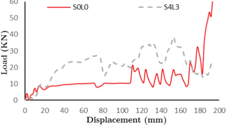
Figure 11: Load-displacement curves of model S4L3 in-group S4 and S0L0.
the annular connection zone (CL) of stiffened stepped tube deforms and affects the final crushing distance. Therefore, the width of stiffeners (SSW/LSW) should be adapted according to the width of the annular zone (CL) in the design process. The determination of the ratio of the stiffener width of the stepped tube to the connection length in Equation (1) and Equation (2) has considered this point, consequently, it cannot exceed this length otherwise, the inversion process is impossible.
In the previous sections, five groups with different configurations of stiffened circular stepped tubes are investigated. The results showed that the stiffened stepped tube could achieve an im-provement of absorbed energy up to 104.23%, specific energy absorption up to 54.9% and crush force efficiency 40.3% as in model S4L3, in comparison with the unstiffened circular stepped tube (S0L0), as shown in Figure 11 and Table 5. The increase of specific energy absorption occurs due to increase in the stiffness of stepped tube by adding the stiffeners in the upper and lower tubes. Hence, the inversion process is unlikely to occur, which is obtained by dissipating a large amount of the crushing force during the inversion process at the inversion regions. Consequently, the energy absorption would increase. In addition, especially in this model, due to the stiffener's width being the same length as step connection. Consequently, the friction between the stiffeners and wall of the stepped tubes plays a significant role, as a high value of the frictions can lead to high absorbed energy. In model S4L3, the influence of external longitudinal stiffeners leads to a significant effect on the inversion stroke length, which provides more stability for the energy ab-sorber. Furthermore, in the model S0L0 the small tube inverts inside the large tube. This mecha-nism happens due to the difference in stiffness between the two tubes, but in the model S4L3 the large tube deforms with the small tube simultaneously. The simultaneous deformation occurs due to increase in the stiffness of the small tube by adding the stiffeners. Hence, the stiffness of the small tube is almost equivalent to the stiffness of the large tube. From these results, it can be said that the simultaneous inversion mechanism is the most efficient mechanism in the design of energy absorbers, which implies high absorbed energy, high specific energy absorption, and high crush force efficiency, as shown in Table 5.
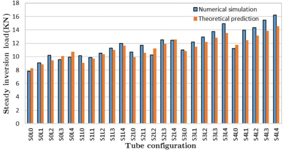
7 VALIDATION OF THE NEW IMPROVED FORMULA
Figure 12: Comparison of numerical results and theoretical predictions of steady inversion load.
8 CONCLUSIONS
In the current paper, a new structural configuration based on the free inversion of stiffened circular stepped tubes is presented to improve/enhance the energy absorption characteristics under axial impact loading. The new configurations of the circular stepped tube are constructed by adding ex-ternal longitudinal stiffeners distributed around the cross section of circular stepped tube. Numeri-cal analyses are conducted to simulate the inversion process of the proposed tubes using the non-linear finite element software (ANSYS-WORKBENCH/LS-DYNA). The numerical models are im-plemented under the axial impact crushing scenario. Furthermore, a new improved formula for pre-diction of steady inversion load is proposed in order to validate the numerical results. A compara-tive study in five groups with different configurations of stiffened circular stepped tubes is conduct-ed to compare the energy absorption characteristics and the inversion mechanism between the new-ly proposed tubes and the conventional stepped tube. The main findings of this study can be drawn as follows:
1. Reinforcing the stepped tubes with external longitudinal stiffeners could imply greatest im-provement for the energy absorption up to 104%, specific energy absorption up to 54.9% and the crush force efficiency up to 40.3% compared to the unreinforced section under axial impact load. Moreover, the stiffened stepped tubes increase the inversion stroke length dur-ing the inversion process which provides more stability for the stepped tube.
2. The width of stiffeners is the most effective parameter in the inversion and deformation mechanism after the end of curling, and it is constrained by the length of connection (CL), hence it cannot exceed this length otherwise the inversion process is impossible
absorbers, which implies high absorbed energy, high specific energy absorption, and high crush force efficiency.
4. The steady inversion loads of the stiffened stepped tube can be predicted by using the new improved formula with an error within 12% hence, the theoretical predictions are in good agreement with the numerical results.
Acknowledgment
The authors gratefully acknowledge the financial supports from National Natural Science Foundation of China under Grants 11472226 and 11672248.
References
Abramowicz, W., Jones, N. (1984). Dynamic axial crushing of circular tubes. International Journal of Impact Engi-neering 2(3): 263-281.
Adachi, T., Tomiyama, A., Araki, W., Yamaji, A. (2008). Energy absorption of a thin-walled cylinder with ribs subjected to axial impact. International journal of impact engineering 35(2): 65-79.
Al-Hassani, S., Johnson, W., Lowe, W. (1972). Characteristics of inversion tubes under axial loading. Journal of Mechanical Engineering Science 14(6): 370-381.
Alghamdi, A. (2001). Collapsible impact energy absorbers: an overview. Thin-walled structures 39(2): 189-213. Andrews, K., England, G., Ghani, E. (1983). Classification of the axial collapse of cylindrical tubes under quasi-static loading. International Journal of Mechanical Sciences 25(9): 687-696.
Chen, D.H., Yang, L. (2012). Numerical Simulation of the Collapse of Stepped Circular Tube Subjected to Oblique Load. Applied Mechanics and Materials, Trans Tech Publ.
Chen, Y., Clausen, A., Hopperstad, O., Langseth, M. (2009). Stress–strain behaviour of aluminium alloys at a wide range of strain rates. International Journal of Solids and Structures 46(21): 3825-3835.
Colokoglu, A., Reddy, T. (1996). Strain rate and inertial effects in free external inversion of tubes. International Journal of Crashworthiness 1(1): 93-106.
Dundulis, R., Kilikevicius, S., Krasauskas, P., Dundulis, G., Rimkevicius, S. (2015). Simulation of a shock absorber with vertical buckling tubes welded in the longitudinal direction. Engineering Failure Analysis 47: 102-110.
Galib, D.A., Limam, A., Combescure, A. (2006). Influence of damage on the prediction of axial crushing behavior of thin-walled aluminum extruded tubes. International Journal of Crashworthiness 11(1): 1-12.
Guist, L., Marble, D.P. (1966). Prediction of the inversion load of a circular tube. Nasa Technical Note. NASA TN D-3622.
Gupta, P. (2014). Numerical Investigation of Process Parameters on External Inversion of Thin-Walled Tubes. Jour-nal of Materials Engineering and Performance 23(8): 2905-2917.
Higuchi, M., Suzuki, S., Adachi, T., Tachiya, H. (2014). Improvement of Energy Absorption of Circular Tubes Sub-jected to High Velocity Impact. Applied Mechanics and Materials, Trans Tech Publ.
Huang, J., Wang, X. (2010). On a new crush trigger for energy absorption of composite tubes. International Journal of Crashworthiness 15(6): 625-634.
Jin, S.Y., Altenhof, W. (2011). An analytical model on the steady-state deformation of circular tubes under an axial cutting deformation mode. International Journal of Solids and Structures 48(2): 269-279.
Jones, N., Birch, R. (1990). Dynamic and static axial crushing of axially stiffened square tubes. Proceedings of the Institution of Mechanical Engineers, Part C: Journal of Mechanical Engineering Science 204(5): 293-310.
Liu, S., Tong, Z., Tang, Z., Liu, Y., Zhang, Z. (2015). Bionic design modification of non-convex multi-corner thin-walled columns for improving energy absorption through adding bulkheads. Thin-Walled Structures 88: 70-81. Lu, G., Yu, T. (2003). Energy absorption of structures and materials, Elsevier.
Luo, Y., Huang, Z., Zhang, X. (2007). FEM analysis of external inversion and energy absorbing characteristics of inverted tubes. Journal of materials processing technology 187: 279-282.
Manual, F. (2013). ANSYS, Release 15.0 ANSYS Documentation. ANSYS Inc, Canonsburg, PA.
Nia, A.A., Parsapour, M. (2014). Comparative analysis of energy absorption capacity of simple and multi-cell thin-walled tubes with triangular, square, hexagonal and octagonal sections. Thin-Walled Structures 74: 155-165.
Niknejad, A., Rezaei, B., Liaghat, G.H. (2013). Empty circular metal tubes in the splitting process–theoretical and experimental studies. Thin-walled structures 72: 48-60.
Olabi, A.-G., Morris, E., Hashmi, M. (2007). Metallic tube type energy absorbers: a synopsis. Thin-walled structures 45(7): 706-726.
Pedersen, P.T. (1973). Buckling of unstiffened and ring stiffened cylindrical shells under axial compression. Interna-tional Journal of Solids and Structures 9(5): 671-691.
Qiu, X., Yu, X., Li, Y., Yu, T. (2016). The deformation mechanism analysis of a circular tube under free inversion. Thin-Walled Structures 107: 49-56.
Qiu, X.M., He, L.H., Gu, J., Yu, X.H. (2014). An improved theoretical model of a metal tube under free external inversion. Thin-Walled Structures 80: 32-37.
Reddy, B. (1980). Buckling of elastic-plastic discretely stiffened cylinders in axial compression. International Journal of Solids and Structures 16(4): 313-328.
Reddy, T. (1992). Guist and Marble revisited—on the natural knuckle radius in tube inversion. International journal of mechanical sciences 34(10): 761-768.
Reid, S. (1993). Plastic deformation mechanisms in axially compressed metal tubes used as impact energy absorbers. International Journal of Mechanical Sciences 35(12): 1035-1052.
Rosa, P., Rodrigues, J., Martins, P. (2003). External inversion of thin-walled tubes using a die: experimental and theoretical investigation. International Journal of Machine Tools and Manufacture 43(8): 787-796.
Ross, C., Johns, T., Beeby, S., May, S. (1994). Vibration of thin-walled ring-stiffened circular cylinders and cones. Thin-walled structures 18(3): 177-190.
Salehghaffari, S., Rais-Rohani, M., Najafi, A. (2011). Analysis and optimization of externally stiffened crush tubes. Thin-walled structures 49(3): 397-408.
Salehghaffari, S., Tajdari, M., Panahi, M., Mokhtarnezhad, F. (2010). Attempts to improve energy absorption char-acteristics of circular metal tubes subjected to axial loading. Thin-Walled Structures 48(6): 379-390.
Santosa, S.P., Wierzbicki, T., Hanssen, A.G., Langseth, M. (2000). Experimental and numerical studies of foam-filled sections. International Journal of Impact Engineering 24(5): 509-534.
Simhachalam, B., Srinivas, K., Rao, C.L. (2014). Energy absorption characteristics of aluminium alloy AA7XXX and AA6061 tubes subjected to static and dynamic axial load. International Journal of Crashworthiness 19(2): 139-152. Tomesani, L. (1997). Analysis of a tension-driven outside-in tube inversion. Journal of materials processing technolo-gy 64(1): 379-386.
Zarei, H., Kröger, M. (2006). Multiobjective crashworthiness optimization of circular aluminum tubes. Thin-walled structures 44(3): 301-308.
Zhang, A., Suzuki, K. (2007). A study on the effect of stiffeners on quasi-static crushing of stiffened square tube with non-linear finite element method. International journal of impact engineering 34(3): 544-555.
Zhang, X., Cheng, G., Zhang, H. (2009). Numerical investigations on a new type of energy-absorbing structure based on free inversion of tubes. International Journal of Mechanical Sciences 51(1): 64-76.
Zhang, X., Zhang, H. (2013). Energy absorption of multi-cell stub columns under axial compression. Thin-Walled Structures 68: 156-163.