ISSN 1549-3636
© 2012 Science Publications
Corresponding Author: Pasumpon Pandian,A., Department of Computer Science and Engineering Sacs Mavmm Engineering College, Madurai, Tamilnadu-625301, India
Hybrid Algorithm for Lossless Image Compression
using Simple Selective Scan order with Bit Plane Slicing
1
Pasumpon Pandian, A. and
2S.N. Sivanandam
1
Department of Computer Science and Engineering,
SACS MAVMM Engineering College, Madurai, Tamilnadu-625301, India
2
Department of Computer Science and Engineering,
Karpagam College of Engineering, Coimbatore, Tamilnadu-641032, India
Abstract: Problem statement: Identifying the new lossless image compression algorithm for high performance applications like medical and satellite imaging; a high quality lossless image is most important when reproduction which leads to classify the data for decision making. Approach: A new lossless hybrid algorithm based on simple selective scan order with Bit Plane Slicing method is presented for lossless Image compression of limited bits/pixel images, such as medical images, satellite images and other still images common in the world. Efficient coding is achieved by run length and modified Huffman coding. This approach is combined with efficient selective scan order for entire image in one pass through. Results: The new hybrid algorithm achieves good compression rate, compared to the existing schemes of coding with different test images. Conclusion: Compared to the existing standards JPEG-LS and CALIC, the compression rate is reduced with our proposed algorithm for different standard test images.
Key words: Lossless image compression, medical and satellite image compression, hybrid algorithm, modified huffman coding, selective scan order, run length encoding, bit plane slicing
INTRODUCTION
Among the fast development of digital know-how, the requirement to save image data is growing. Lossless image compression is very much preferred in applications where the images are focused for additional processing, classification and forecasting, recognizing and frequent compression or decompression. This is usually an alternate for images obtained at extremely huge expenditure, or in applications where the preferred quality of the reconstructed image is yet unknown. Thus, satellite images (Magli, 2009), medical images (Philips et al., 2001; Ghrare et al., 2009) and other still images used in surveillance camera are all the applications of lossless compression.
Normally, lossless compression is prepared through simple sequencing of bits based on selective scan order and then the run length is calculated and modified Huffman encoding scheme is applied similar to an entropy coder. Since these samples disclose some residual correlation, modern lossless image compression schemes accept three separate and autonomous phases, slicing, sequencing and entropy coding (Podlasov and Franti, 2006; Cai and Li, 2005).
operation based on the scan order sorting methods. Optimum cost is required in the coding phase, particularly when a Huffman coding is applied for compression.
Apart from this compression rate, the above algorithm are also tried to improve the computational complexity, which is also important for real world applications. For example, in the lossless JPEG standard (Weinberger et al., 2000), two different coding is specified: One is arithmetic coding and another is Huffman coding. While the compression gap between the Huffman and the arithmetic coding is considerable, the latter did not achieve extensive use, possibly due to its high complexity requirements (Podlasov and Franti, 2006; Cai and Li, 2005). Although the Run length and Modified Huffman coding scheme can be applied to reduce the coding cost, the resulting complexity might be low for some applications such as in real-time compression of images.
This reading presents a new hybrid image coding algorithm HALIC which is based on simple sequencing with scan order followed by finding the run lengths of binary bits in the bit plane, which is an easy process and encodes the run lengths by applying Modified Huffman coding scheme. In this proposed algorithm, each image is processed into four parts: (1) bit plane slicing (2) sequencing with selected scan order, (3) calculate the run lengths and (4) apply modified Huffman coding. As a result, most of the neighborhood bits are arranged sequentially based on the scan order, which is then coded with a run length and modified Huffman entropy coding algorithm. By simply coding the pixels with selected scan order and hybrid coding scheme, excellent performance can be achieved with low computational cost. Moreover, with the aid of modified Huffman coding, the images are compressed with the high coding efficiency, compared to JPEG-LS (Wang et al., 2007; Wu and Memon, 1997; 2000) and CALIC standards.
MATERIALS AND METHODS
The proposed algorithm is applied for compressing the satellite STI and medical MRI brain images STI with low computational cost. This study is organized as follows, first section presents the coding algorithm requirements followed by our proposed algorithm HALIC method have presented which includes an overall introduction and descriptions. Then, simulation results are tabulated and discussed. Finally, Conclusions are drawn.
Coding algorithm requirements:
Modified huffman coding scheme: Generally, Huffman encoding algorithm starts by constructing a list of all the symbols in descending order of their
probabilities. This scheme constructs from the bottom to top, a binary tree with a symbol at every leaf. This is done in different steps, where at each step two symbols with the smallest probabilities are selected, added to the top of the partial tree, deleted from the list and replaced with an auxiliary symbol representing the two original symbols. When the list is reduced to just one auxiliary symbol (representing the entire symbol), the tree is absolute tree. The tree is then traversed to determine the code words of the symbols.
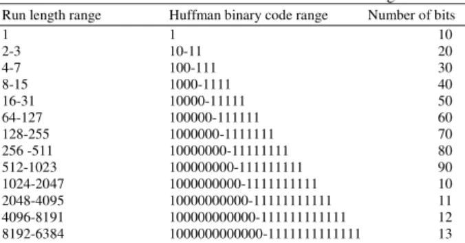
Where as our modified Huffman coding scheme is very simple, the Huffman binary tree is constructed based on the run lengths calculated from RLE method. The tree is constructed from top to bottom, starts from run length 1 to maximum run length in the image bits. For example, the Huffman tree is constructed for run lengths from 1 to 32 as shown in the Fig. 1, which contains nodes and edges. The node consists of run lengths and edge contains the binary bit either 0 or 1. The Root node is T, which is the first node, traversal starts from. This modified Huffman tree is constructed from top to bottom by arranging the run lengths in binary tree format along with assigning of binary bits 0 and 1 for every pair of child in the Huffman binary tree. There is no need of traversal to determine the code words of the run length and no need for calculating the frequency of occurrence of run lengths, therefore, time complexity is reduced. The modified Huffman table contains the different run lengths and their corresponding Huffman binary code, which is shown in Table 1. The Table 1 contains the Run length range and their corresponding Huffman binary code range. This coding scheme is a static variable length coding scheme.
Scan order selection: In modern compression methods like JPEG-LS, Predictive modeling method is used and it exploits spatial correlations by predicting the value of the current pixel by a function of its already coded neighboring pixels. In Context models, every distinctive pixel combination of the neighborhood is considered as its own coding context. The probability distribution of the pixel values is estimated for each context separately based on past samples. In grayscale images, however, the number of possible pixel combinations is huge and only a small neighborhood can be used. The number of contexts must therefore be reduced by context quantization. This approach, combined with predictive modeling, has been used in the CALIC algorithm.
Fig. 1: Modified huffman Tree for the run lengths
Fig. 2: Types of basic scan orders
Table 1: Modified Huffman Table for the different run lengths
Run length range Huffman binary code range Number of bits
1 1 10
2-3 10-11 20
4-7 100-111 30
8-15 1000-1111 40
16-31 10000-11111 50
64-127 100000-111111 60
128-255 1000000-1111111 70
256 -511 10000000-11111111 80
512-1023 100000000-111111111 90
1024-2047 1000000000-1111111111 10
2048-4095 10000000000-11111111111 11 4096-8191 100000000000-111111111111 12 8192-6384 1000000000000-1111111111111 13
The Scan order is a sequencing method and is a two-dimensional spatial-accessing methodology (Drost and Bourbakis, 2001; Maniccam and Bourbakis, 2001;
Memon et al., 2000; Ouni et al., 2011). Sequencing of bits can represent and generate a large number of wide varieties of scan order. In this algorithm, there are ten basic scan orders as shown in Fig. 2 have been used for sequencing the neighborhood bits in a bit plane. The time complexity of scan ordering of image array is O (n2), where n x n is the order of Image array.
Fig. 3:Selection of scan order
Fig. 4:HALIC Encoder and decoder
Algorithm-I:
Step-1: Read the image X in array format
Step-2: Repeat the Step-2 until scan order code s ≤ 9, initially s = 0
• Select the scan order code s which is 4-bit length. Arrange the pixels in X into the specific scan order s as shown in the Fig. 1. The result is stored in the Ds.
• Apply the Linear Prediction and DPCM method to find the difference on the data Ds from Step-2 (i), which improves performance of the compression. It is represented as Dp in Eq. 1
• Apply the Huffman encoding on the Dp, • Calculate the Compression Rate CR(Dp) for
the scan order s and Increment the s-value by 1
{
} {
}
p s s
D (i, j) D (i, j) D (i 1, j),
for all i 1 n , j 1 n
= − − = ⋯ = ⋯
(1)
Step-3: Select the scan order based on the objective function in Eq. 2:
(
p)
max CR(D ,s) ,
where s={0...9}
(2)
Step-4: Return the s-value to the HALIC Encoder.
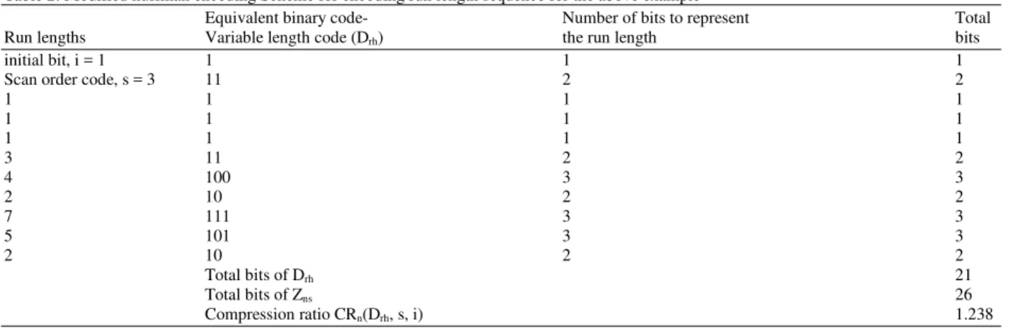
Table 2: Modified huffman encoding Scheme for encoding run length sequence for the above example
Equivalent binary code- Number of bits to represent Total
Run lengths Variable length code (Drh) the run length bits
initial bit, i = 1 1 1 1
Scan order code, s = 3 11 2 2
1 1 1 1
1 1 1 1
1 1 1 1
3 11 2 2
4 100 3 3
2 10 2 2
7 111 3 3
5 101 3 3
2 10 2 2
Total bits of Drh 21
Total bits of Zns 26
Compression ratio CRn(Drh, s, i) 1.238
Table 3: Modified Huffman decoding Scheme for the discussed example Equivalent binary code- Variable
length code, Drh Run length, Dr
1 initial bit, i = 1
11 Scan order code, s = 3
1 1
1 1
1 1
11 3
100 4
10 2
111 7
101 5
10 2
Table 4: Run length decoding Scheme for the discussed example
Bits to be replaced Actual bits to
Run length, Dr with run length stored, Zns
1 Initial bit, i = 1 1
1 0 0
1 1 1
3 0 0, 0, 0
4 1 1, 1, 1, 1
2 0 0, 0
7 1 1, 1, 1 ,1, 1, 1, 1
5 0 0, 0, 0, 0, 0
2 1 1, 1
HALIC encoding algorithm: The Compression process of the HALIC algorithm has two steps.
Algorithm-II:
Step-1: Find bit planes of given 8-bit image X(I,j), where i, j is the position of the pixel, i = {1, …, m}, j = {1, …, m} and m is the number of rows and columns of the image (the value of n is usually in powers of 2, i.e., 256, 512, 1024 and image should be a square image). The binary image Zn(i, j) is found with the Eq. 3, Z0 is the 0th Bit plane (LSB) and Z7 is the 7th Bit plane (MSB):
{
} {
}
n n
X(i, j)
Z (i, j) mod , 2 for all i 2
1 m , j 1 m ,and n [0,7]
=
= ⋯ = ⋯ =
(3)
Step-2: Repeat the Step-2 until bit plane code n ≤ 7, initially n = 0:
• Select the scan order code s for the image X, s is 4-bit length code. Arrange the pixels of ‘Zn’ into the specific selected scan order‘s’ found by the Algorithm-I. The result is stored as ‘Zns’
• Calculate the run lengths of Zns using RLE method, store the run length as Dr and store the initial bit as ‘i’. Example, Zns = [1, 0, 1, 0, 0, 0, 1, 1, 1, 1, 0, 0, 1, 1, 1, 1, 1, 1, 1, 0, 0, 0, 0, 0, 1, 1] and s = 3, then Dr = [1, 1, 1, 3, 4, 2, 7, 5, 2], initial bit i = 1 and scan order s = 3
• Apply the modified Huffman encoding on Dr. Dr consists of run lengths of sequenced binary plane Zns. This bits are encoded with modified Huffman coding as variable length code which is used to reduce the number of bits of Dr. Then the result is stored as Drh which is shown in the Table 2
• Calculate the Compression Rate CRn (Drh, s, i) for the scan order s and Increment the n value by 1 for next bit plane compression
Finally, the code book contains (Drh, s, i) n the compressed image.
HALIC decoding algorithm: Similar to the compression, the decompression process of the proposed algorithm has two steps:
Algorithm-III:
Step-1: Repeat the Step-2 until bit plane code n ≤ 7, initially n = 0:
• Decode the Dr with run length decoding method and it is represented as Zns, for example the decoded bits are tabulated in Table 4
• Arrange each bit in the selected scan order (for example, s = 3, spiral In )and it is represented as Zn Step-2: Finally Bit plane unification is done to get the reconstructed quality image, as shown in Eq. 4:
(
)
{
} {
}
7
n n n 0
X(i, j) Z (i, j) 2 ,
for all i 1 m , j 1 m
=
= ∑ × = ⋯ = ⋯
(4)
RESULTS
To asses the performance of our proposed HALIC coder, a image test set including five images STI with a wide variety of features are used here for
the simulations. These images are monochrome-8 bits/pixel images which are shown in Fig. 5.
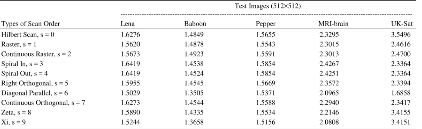
The Lossless image coder (Drost and Bourbakis, 2001; Cai and Li, 2005), which is the core of the CALIC (Wang et al., 2007; Wu and Memon, 1997; 2000) and JPEG-LS standard (Weinberger et al., 2000), is used for comparison. The compression ratio of test images for various scan order are tabulated in Table 5, which is helpful for selecting the scan order based on the maximum compression ratio.
The compression ratio of test image bit planes with our proposed algorithm is tabulated in Table 6. The average compression ratio is limited to 3.45. Our proposed HALIC coder shows a good performance on an average in comparison with CALIC with
Huffman coding and JPEG-LS.
Table 5: Comparison of Compression Ratio of Scan Order Selection algorithm for the test images Test Images (512×512)
---
Types of Scan Order Lena Baboon Pepper MRI-brain UK-Sat
Hilbert Scan, s = 0 1.6276 1.4849 1.5655 2.3295 3.5496
Raster, s = 1 1.5620 1.4878 1.5543 2.3015 2.4616
Continuous Raster, s = 2 1.5673 1.4923 1.5591 2.3013 2.4700
Spiral In, s = 3 1.6419 1.4538 1.5854 2.4267 2.3364
Spiral Out, s = 4 1.6419 1.4524 1.5854 2.4251 2.3364
Right Orthogonal, s = 5 1.5955 1.4545 1.5669 2.3572 2.3394
Diagonal Parallel, s = 6 1.5029 1.3505 1.5371 2.0965 1.6858
Continuous Orthogonal, s = 7 1.6273 1.4544 1.5588 2.2940 2.3417
Zeta, s = 8 1.5890 1.4335 1.5534 2.2146 3.4155
Xi, s = 9 1.5244 1.3658 1.5156 2.0808 3.4151
Table 6: Comparisons of compression ratio of HALIC coder with selective scan for test image bit planes Test Images (512×512) with Scan order
---
Bit Lena, Baboon Pepper, MRI-brain, UK-Sat,
Plane spiral in continuous raster spiral In spiral In hilbert
0 1.2751 1.2798 1.2738 1.76140 2.7947
1 1.2780 1.2785 1.2744 1.77950 2.8074
2 1.2985 1.3030 1.2777 2.02970 2.7923
3 1.4785 1.3663 1.6026 2.36330 3.2192
4 2.0373 1.5348 1.8638 3.83450 3.3515
5 2.8702 1.9854 2.6249 5.72550 4.8813
6 4.0970 3.0010 4.1769 11.1527 5.6295
7 7.0222 7.0397 7.1757 13.4889 9.0335
Average 2.6696 2.3486 2.6587 5.26690 4.3137
Table 7: Compression results (bits per pixel) for the different test
images
Compression rate in bits/pixel --- Test Images
(512×512) HALIC JPEG-LS CALIC
Lena 2.9967 4.95970 4.20560
Baboon 3.4063 7.83470 4.39020
Pepper 3.0090 6.87050 4.61870
MRI-brain 1.5189 3.46430 2.34960
UK-Sat 1.8546 4.93260 4.05970
Average 2.5571 5.61236 3.92476
DISCUSSION
The HALIC coder achieves good compression rate as 2.56 bits/pixel on an average compared to the performance of other lossless coders, which is shown in Table 7. This proposed HALIC algorithm is more suitable for applications like compression of medical images (Ghrare et al., 2009) and satellite images (Magli, 2009) where image classifications required.
CONCLUSION
This study addresses a new hybrid image coding algorithm based on a sequencing that is simple to cast and encode the bit planes. The core idea is to sequence the bits in the bit plane with selected scan order and then encode the bits by the combination of Run Length and modified Huffman coding scheme. Moreover, two coding modes are proposed for efficient compression requirements particularly in the applications of medical and satellite image compression. The proposed HALIC lossless coding algorithm obtains the good results when compared to the JPEG-LS and CALIC standards achieved on specified image test set.
REFERENCES
Drost, G.W. and N.G. Bourbakis, 2001. A hybrid system for real-time lossless image compression. Microproc. Microsyst., 25: 19-31. DOI: 10.1016/S0141-9331(00)00102-2
Ghrare, S.E., M.A.M. Ali, K. Jumari and M. Ismail, 2009. An efficient low complexity lossless coding algorithm for medical images. Am. J. Applied Sci.,
6: 1502-1508. DOI:
10.3844/ajassp.2009.1502.1508
Magli, E., 2009. Multiband lossless compression of hyperspectral images. IEEE Trans. Geosci. Remote
Sens., 47: 1168-1178. DOI:
10.1109/TGRS.2008.2009316
Maniccam, S.S. and N.G. Bourbakis, 2001. Lossless image compression and encryption using SCAN. J. Patt. Recogn., 34: 1229-1245. DOI: 10.1016/S0031-3203(00)00062-5
Memon, N., D.L. Neuhoff and S. Shende, 2000. An analysis of some common scanning techniques for lossless image coding. IEEE Trans. Image Proc., 9: 1837-1848. DOI: 10.1109/83.877207
Ouni, T., A. Lassoued and M. Abid, 2011. Gradient-based space filling curves: Application to lossless image compression. Proceedings of the IEEE International Conference on Computer Applications and Industrial Electronics, Dec. 4-7, IEEE Xplore Press, Penang, pp: 437-442. DOI: 10.1109/ICCAIE.2011.6162175
Philips, W., S.V. Assche, D.D. Rycke and K. Denecker, 2001. State-of-the-art techniques for lossless compression of 3D medical image sets. Comput. Med. Imag. Graph., 25: 173-185. PMID: 11137794
Podlasov, A. and P. Franti, 2006. Lossless image compression via bit-plane separation and multilayer context tree modeling. J. Elec. Imag., 15: 1-1.
Wang, H., S.D. Babacan and K. Sayood, 2007. Lossless hyperspectral-image compression using context-based conditional average. IEEE Trans. Geosci. Remote Sens., 45: 4187-4193. DOI: 10.1109/TGRS.2007.906085
Weinberger, M.J., G. Seroussi and G. Sapiro, 2000. The LOCO-I lossless image compression algorithm: Principles and standardization into JPEG-LS. IEEE Trans. Image Proc., 9: 1309-1324. DOI: 10.1109/83.855427
Wu, X. and N. Memon, 1997. Context-based, adaptive, lossless image coding. IEEE Trans. Commun., 45: 437-444. DOI: 10.1109/26.585919
Wu, X. and N. Memon, 2000. Context-based lossless interband compression-extending CALIC. IEEE Trans. Image Proc., 9: 994-1001. DOI: 10.1109/83.846242