An Iterative Frequency-Domain Decision-Feedback
Receiver for MC-CDMA Schemes
Rui Dinis, Paulo Silva and Ant´onio Gusm˜ao
CAPS-IST, Tech. Univ. of Lisbon, Av. Rovisco Pais, 1049-001 Lisboa, Portugal,
Phone: +351 218419358; Fax: +351 218465303; email: [email protected]
Abstract - The MC-CDMA techniques (Multicarrier Coded Division Multiple Access) combine a CDMA scheme with an OFDM modulation (Orthogonal Frequency Divi-sion Multiplexing), so as to allow high transmisDivi-sion rates over severely time-dispersive channels without the need of a complex receiver implementation.
In this paper we propose an iterative frequency-domain decision-feedback receiver for MC-CDMA signals. The proposed receiver has excellent performance, close to the single-code MFB (Matched Filter Bound), even for severe time-dispersive scenarios and/or in the presence of strong interfering channels.
I. Introduction
The MC-CDMA schemes (Multicarrier Coded Division Multiple Access) [1], [2] combine a CDMA scheme with an OFDM modulation (Orthogonal Frequency Division Mul-tiplexing) [3], so as to allow high transmission rates over severe time-dispersive channels without the need of a complex receiver implementation. As with conventional OFDM, an appropriate cyclic extension is appended to each transmitted block. Since the spreading is made in the frequency do-main, the time synchronization requirements are much lower than with conventional Direct Sequence CDMA schemes. Moreover, by spreading a given data symbol over several subcarriers, there is an inherent diversity effect in frequency-selective channels. However, since transmission over those channels destroys the orthogonality between spreading codes, an FDE (Frequency-Domain Equalizer) is required before the de-spreading operation [4].
Since conventional FDE schemes can be regarded as infinite-length linear equalizers, we can have significant noise enhancement when a ZF (Zero Forcing) equalizer is em-ployed in channels with deep in-band notches, which can lead to significant performance degradation. For this reason, an MMSE (Minimum Mean-Squared Error) FDE equalizer is usually preferable [2], [4]. However, an MMSE FDE does not perform an ideal channel inversion. Therefore, when this type of equalizer is employed within MC-CDMA systems we are not able to fully orthogonalize the different spreading codes. This means that we can have severe interference levels especially when different powers are assigned to different spreading codes.
For this reason, it is usually preferable to employ a non-linear frequency-domain receiver. For this propose, we will consider an iterative decision-feedback receiver that can be regarded as an extension to multicode MC-CDMA schemes of the IB-DFE (Iterative block Decision Feedback Equalizer), recently proposed for block transmission with single-carrier modulations [5], [6]. The proposed technique can also be employed successfully in the downlink transmission (i.e., the transmission from the BS (Base Station) to the MT (Mobile Terminal)). In that case, we estimate not just the data symbols associated to the desired user but also the data symbols from the other users. Therefore, our receiver technique can be regarded as a frequency-domain multiuser detection technique with parallel interference cancelation.
This paper is organized as follows: Sec. II describes the transmitted signals. The proposed receiver structure is pre-sented in sec. III. As set of performance results is prepre-sented in sec. IV and sec. V is concerned with the conclusions of this paper.
II. Transmitted Signals
In this paper we consider a multicode transmission within MC-CDMA systems employing frequency-domain spreading. A constant spreading factor K is assumed (the extension to VSF schemes (Variable Spreading Factor) is straightforward). The frequency-domain block to be transmitted is an interleaved version 1 of the block fSk; k = 0; 1; : : : ; N ¡ 1g, where
N = KM, with K denoting the spreading factor and M the number of data symbols associated to each spreading code. The frequency-domain symbols are given by
Sk = P
X
p=1
»pSk;p (1)
where»pis an appropriate weighting coefficient that accounts for the power control in the downlink (the power associated to the pth spreading code is proportional to »p2) and Sk;p = Ck;pAbk=Kc;p is the kth chip for the pth spreading code (bxc
denotes ’larger integer not higher that x’), where fAk;p; k = 0; 1; : : : ; M ¡ 1g is the block of data symbols associated to 1Typically, the transmitted frequency-domain block is generated by
submit-ting the blockfSk; k = 0; 1; : : : ; N ¡ 1g to a rectangular interleaver with dimensionsK £ M, i.e., the different chips associated to a different data symbol are spaced byK subcarriers
thepth spreading code and fCk;p; k = 0; 1; : : : ; N ¡ 1g is the corresponding spreading sequence. An orthogonal spreading is assumed throughout this paper, withCk;pbelonging to a QPSK constellation (Quadrature Phase Shift Keying). Without loss of generality, it is assumed that jCk;pj = 1. After removing the cyclic extension, the received samples are passed to the frequency domain, leading to the blockfYk; k = 0; 1; : : : ; N ¡ 1g. It is well-known that, when the cyclic extension is longer than the overall channel impulse response, the samplesYk can be written as
Yk= HkSk0 + Nk; (2)
whereHk andNk denote the channel frequency response and the noise term for thekth frequency, respectively, and the block fS0
k; k = 0; 1; : : : ; N ¡1g is an interleaved version of the block
fSk; k = 0; 1; : : : ; N ¡ 1g.
Since the orthogonality between spreading codes is lost in frequency selective channels, the de-spreading operation cannot be applied directly to the frequency-domain samples Yk.
III. Proposed Receiver Structure
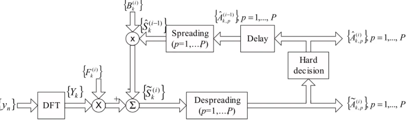
Fig. 1 presents the receiver structure that we are considering in this paper. For a given iteration i, the output samples are given by
~
Sk(i)= Fk(i)Yk¡ Bk(i)S^(i¡1)k (3)
where fFk(i); k = 0; 1; : : : ; N ¡ 1g and fB(i)k ; k = 0; 1; : : : ; N ¡ 1g denote the feedforward and the feedback coefficients, respectively. f ^S(i¡1)k = PPp=1»pS^k;p(i¡1); k =
0; 1; : : : ; N ¡ 1g, with ^Sk;p(i¡1)= ^A(i¡1)bk=Kc;pCk;p. In (3), ^A(i¡1)k
denotes the estimate ofAk;pfor the(i¡1)th iteration, obtained from ~ Ak;p = X k02ªk ~ Sk0Ck¤0;p: (4)
withªk = fk; k + M; : : : ; k + (K ¡ 1)Mg denoting the set of frequencies employed to transmit thekth data symbol of each spreading code.
The coefficients Fk(i) and Bk(i) (k = 0; 1; : : : ; N ¡ 1) are chosen so as to maximize the overall SNR (Signal-to-Noise Ratio) in the samples ~Sk(i). It can be shown that the optimum coefficients are given by
B(i)k = ½(i¡1)³F(i)
k Hk¡ °(i) ´ (5) and Fk(i) = SNR ¢ Hk¤ 1 + SNR(1 ¡ (½(i¡1))2)jHkj2; (6) respectively, where °(i) = 1 N N¡1X k=0 Fk(i)Hk (7)
andSNR = E[jSkj2]=2¾2N, with¾2N denoting the variance of the real and imaginary parts of the noise component.
The coefficient½(i¡1), which can be regarded as the block-wise reliability of the decisions used in the feedback loop (from the previous iteration), is given by
½(i¡1)= E[ ^S(i¡1)
k Sk¤]=E[jSkj2]: (8)
This correlation factor is crucial for the good performance of the proposed receivers. Assuming uncorrelated data blocks, it can be easily shown that
½(i¡1)=XP p=1 »2 p E[ ^Ak;pA¤k;p] E[jAk;pj2] = P X p=1 »2 p½(i¡1)p ; (9) with ½(i¡1) p =E[ ^Ak;pA ¤ k;p] E[jAk;pj2] : (10)
If theAk;pbelong to a QPSK constellation, it can be shown that
½(i¡1)
p = 1 ¡ 2Pb;p(i¡1); (11)
withPb;p(i¡1)denoting the average BER for thepth user, at the (i ¡ 1)th iteration. This BER rate can be estimated during the training phase, using reference blocks. We can also employ the method proposed in [6] for estimating½p.
It should be noted that, for the first iteration (i = 0), we do not have any information about Sk and the correlation coefficient is zero. This means that Bk(0)= 0 and
Fk(0)= SNR ¢ Hk¤
1 + SNRjHkj2; (12)
corresponding to the optimum frequency-domain equalizer coefficients under the MMSE criterion [4]. After the first iteration, and if the residual BER is not too high, at least for the spreading codes for which a higher transmit power is associated, we have ^Ak;p = Ak;p for most of the data symbols, leading to ^Sk ¼ Sk. Consequently, we can use the feedback coefficients to eliminate a significant part of the residual interference.
For M = 1 and a Fourier spreading/despreading, the MC-CDMA scheme considered in this paper is equivalent to a single-carrier block-transmission scheme [7], and our receiver reduces to the IB-DFE receiver described in [5], [6].
IV. Performance Results
In this section we present a set of performance results concerning the proposed receiver structure. We consider the downlink transmission, with each spreading code intended to a given user. It is assumed thatN = 256 (similar results could be obtained for other values of N) and the data symbols are selected from a QPSK constellation under a Gray mapping rule. A linear power amplifier is assumed at the transmitter and we consider two channel models:
² Channel I: Power delay profile type C for the HIPER-LAN/2 (HIgh PERformance Local Area Network) [8], with uncorrelated Rayleigh fading on the different paths. The subcarrier separation is 0.2MHz.
X
{ }
Y
k{ }
(i) k F DFT{ }
y
n x{ }
(i) k BΣ
Hard decision{ }
Ai p P p k , 1,..., ~() , ={ }
~
(i) kS
{ }
Ai p P p k , 1,..., ˆ() , ={ }
ˆ
(i−1) kS
+ Delay{ }
Ai p P p k , 1,..., ˆ( 1) , = − Spreading (p=1,...,P) Despreading (p=1,...,P)Fig. 1. Proposed iterative receiver.
² Channel II: Uncorrelated Rayleigh fading on the different subcarriers.
Perfect synchronization and channel estimation is assumed in all cases.
For the sake of comparisons, we included the SU perfor-mance (Single-User), which, for thekth data symbol could be defined as Pb;SU;k= E 2 4Q 0 @s2Eb N0 1 K X k02ªk jHk0j2 1 A 3 5 ; (13)
where the expectation is over the set of channel realizations (it is assumed that E[jHkj2] = 1 for any k). We also include the corresponding MFB performance (Matched Filter Bound), defined as Pb;MF B = E " Q Ãs 2Eb N0 1 N X k jHkj2 !# : (14)
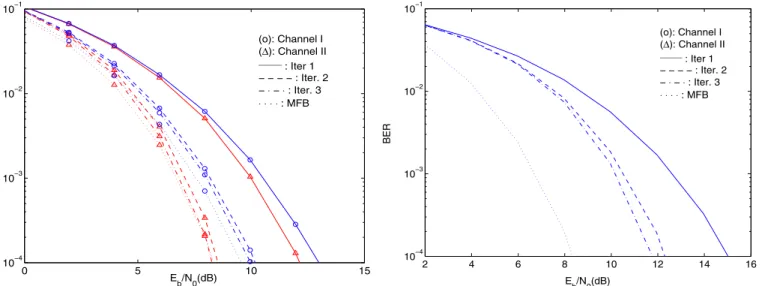
Let us first assume that the spreading factor is K = 256, i.e.,M = 1 and all subcarriers are used to transmit a given data symbol. Figs. 2 and 3 concern the case when the same power is attributed to all spreading sequences. In fig. 2 we haveKU = 256 users (i.e., a fully loaded system) and in fig. 2 we haveKU = 64 users. The first iteration corresponds to the conventional linear FDE receiver [4]. Clearly, the iterative procedure allows a significant improvement relatively to the conventional linear FDE: for both channels, we can have gains of about 6dB for BER= 10¡4 from the first iteration to the
third iteration (although the performance in channel II is better due to the higher diversity effects), especially for a fully loaded system. Moreover, the achievable performances are close to the MFB (identical to the SU performance when N = K) after three iterations.
Let us consider now a fully loaded scenario where the power attributed toK=2 = 128 users is 6dB below the power attributed to the otherK=2 = 128 users. Clearly the low-power users face strong interference levels. Figs. 4 and 5present the performance for the low-power and the high-power users, respectively, in channel II. Once again, the iterative receiver allows significant performance improvements. From these fig-ures, it is clear that gains associated to the performance of
0 5 10 15 10−4 10−3 10−2 10−1 E b/N0(dB) BER (o): Channel I (∆): Channel II _____ : Iter 1 − − − − : Iter. 2 −⋅ − ⋅ : Iter. 3 ⋅ ⋅ ⋅ ⋅ : MFB
Fig. 2. Average BER performance whenK = 256 (M = 1) and KU= 256 users, with the same attributed power.
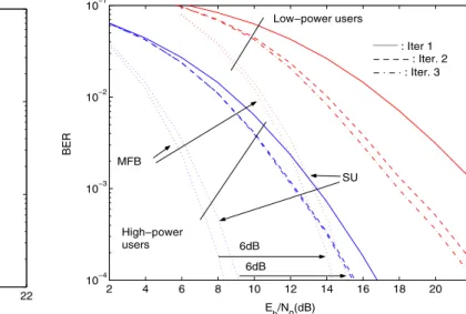
the iterative procedure are higher for low-power users and the BERs are closer to the MFB than for the high-power users: for low-power users we can have gains of about 6dB form the first iteration to the third, and the BER after three iterations is less than 2dB from the MFB; for high-power user, we have gains of about 3dB from the first iteration to the third and the BERs are still more than 3dB from the MFB after three iterations. This can be explained as follows: the BER is much lower for high-power users, allowing an almost perfect interference cancelation of their effects on low-power users; the higher BERs for the low-power users preclude an appropriate interference cancelation when we detect high-power users (see also figure 6, where the BERs are expressed as a function of theEb=N0of high-power users, 6dB below theEb=N0of low-power users). A similar behavior was observed for channel I (see fig. 7).
Let us consider now the case whereK = 16 (i.e., M = 64). Fig. 8 concerns the case when the same power is assigned to all spreading sequences and we have KU = 16 users (i.e., a fully loaded system). Although the iterative procedure allows
0 5 10 15 10−4 10−3 10−2 10−1 Eb/N0(dB) BER (o): Channel I (∆): Channel II _____ : Iter 1 − − − − : Iter. 2 −⋅ − ⋅ : Iter. 3 ⋅ ⋅ ⋅ ⋅ : MFB
Fig. 3. Average BER performance whenK = 256 (M = 1) and KU= 64 users, with the same attributed power.
2 4 6 8 10 12 14 16 10−4 10−3 10−2 10−1 Eb/N0(dB) BER (o): Channel I (∆): Channel II _____ : Iter 1 − − − − : Iter. 2 −⋅ − ⋅ : Iter. 3 ⋅ ⋅ ⋅ ⋅ : MFB
Fig. 4. Average BER performance in channel I, whenK = KU= 256, for the low-power users.
gains of about 2dB, the achievable performances are identical after iteration two and after iteration three, and still far from the MFB and the SU performances (the SU performance is slightly worse that the MFB when K < N). Contrarily to the case where N = K, both channels have identical performances. This is a consequence of the smaller value of K: although the diversity effects are better for channel II, we cannot take advantage of it since a given data symbol is spread by a smaller number of subcarriers.
Let us consider a fully-loaded scenario where the power attributed toK=2 = 8 users is 6dB below the power attributed to the other K=2 = 8 users. Figs. 9 and 10 concern chan-nel I and chanchan-nel II, respectively. Once again, the iterative receiver allows higher gains for low-power users significant
2 4 6 8 10 12 14 16 10−4 10−3 10−2 10−1 Eb/N0(dB) BER (o): Channel I (∆): Channel II _____ : Iter 1 − − − − : Iter. 2 −⋅ − ⋅ : Iter. 3 ⋅ ⋅ ⋅ ⋅ : MFB
Fig. 5. Average BER performance in channel I, whenK = KU= 256, for the high-power users.
2 4 6 8 10 12 14 16 18 20 22 10−4 10−3 10−2 10−1 E b/N0(dB) BER _____ : Iter 1 − − − − : Iter. 2 −⋅ − ⋅ : Iter. 3 ⋅ ⋅ ⋅ ⋅ : MFB High−power users Low−power users 6dB
Fig. 6. Average BER performance in channel I, whenK = KU= 256, for low-power and high-power users.
performance improvement. As expected, similar results were observed for channel I and channel II.
V. Conclusions and Final Remarks
In this paper we presented an iterative frequency-domain receiver for multicode transmission within an MC-CDMA sys-tem. For a given iteration, we employ previous data estimates to cancel the residual interference.
The proposed receiver has excellent performance, close to the SU and MFB performances when the spreading factor is high, even for severe time-dispersive scenarios and/or in the presence of strong interfering channels.
It should be noted that the proposed receiver is very flexible, with the number of iterations dependent on the type of receiver and/or the quality requirements for a given service.
2 4 6 8 10 12 14 16 18 20 22 10−4 10−3 10−2 10−1 Eb/N0(dB) BER _____ : Iter 1 − − − − : Iter. 2 −⋅ − ⋅ : Iter. 3 ⋅ ⋅ ⋅ ⋅ : MFB Low−power users High−power users 6dB
Fig. 7. Average BER performance in channel II, whenK = KU = 256, for low-power and high-power users.
2 4 6 8 10 12 14 16 18 20 22 10−4 10−3 10−2 10−1 E b/N0(dB) BER _____ : Channel I − − − − : Channel II SU Iters. 2 and 3 MFB Iter. 1
Fig. 8. Average BER performance whenK = 16 (M = 64) and KU= 16 users, with the same attributed power.
References
[1] S. Hara and R. Prasad, “Overview of Multicarrier CDMA”, IEEE Comm. Magazine, Dec. 1997.
[2] S. Hara and R. Prasad, “Design and Performance of Multicarrier CDMA System in Frequency-Selective Rayleigh Fading Chan-nels”, IEEE Trans. on Vehicular Technology, Vol. 48, No. 5, Sep. 1999.
[3] L.Cimini Jr., “Analysis and Simulation of a Digital Mobile Channel using Orthogonal Frequency Division Multiplexing”, IEEE Trans. on Comm., Vol. 33, No. 7, July 1985.
[4] H. Sari, “Orthogonal Multicarrier CDMA and its Detection on Frequency-Selective Channels”, European Trans. on Telecomm., Vol. 13, No. 5, pp. 439–445, Sep.–Oct. 2002.
[5] N. Benvenuto and S. Tomasin, “Block Iterative DFE for Single
2 4 6 8 10 12 14 16 18 20 22 10−4 10−3 10−2 10−1 Eb/N0(dB) BER _____ : Iter 1 − − − − : Iter. 2 −⋅ − ⋅ : Iter. 3 Low−power users High−power users 6dB 6dB MFB SU
Fig. 9. Average BER performance in channel I, whenK = KU= 16, for low-power and high-power users.
2 4 6 8 10 12 14 16 18 20 22 10−4 10−3 10−2 10−1 Eb/N0(dB) BER _____ : Iter 1 − − − − : Iter. 2 −⋅ − ⋅ : Iter. 3 Low−power users High−power users 6dB 6dB MFB SU
Fig. 10. Average BER performance in channel II, whenK = KU= 16, for low-power and high-power users.
Carrier Modulation”, IEE Elec. Let., Vol. 39, No. 19, pp. 1144– 1145, Sep. 2002.
[6] R. Dinis, A. Gusm˜ao, and N. Esteves, “On Broadband Block Transmission over Strongly Frequency-Selective Fading Chan-nels”, Proc. Wireless 2003, Calgary, Canada, July 2003. [7] K. Br¨uninghaus and H. Rohling, “Multi-carrier Spread Spectrum
and its Relationship to Single-carrier Transmission”, IEEE VTC’98, May 1998.
[8] ETSI, “Channel models for HIPERLAN/2 in Different Indoor Scenarios”, ETSI EP BRAN 3ERI085B, pp. 1-8, March 1998.