Pipeline Stress Analysis Through Stress Function Fittings
Abstract
This work presents a hybrid experimental technique for stress analysis in pipes due to soil-pipe interaction. It was used a variation of Digital Speckle Pattern Interferometry (DSPI) combined with a small indentation setup for acquiring radial displacement points. Data collected are fitted under the Airy stress functions method for the determination of displacements and strain components. The radial displacement data is fitted in to extract Airy stress function coefficients in a short combination selected specifically for the analysis of stress fields in pipes. This technique is of great utility as an auxiliary approach to the actual field data compilation.
Keywords
hybrid technique, Airy Stress Function, instrumented indentation, stress fields in pipes
1 INTRODUCTION
This paper presents an interesting technique to evaluate radial displacement data to obtain the strain and the stress field information present in pipelines, Freire et al. (2009). Such analysis is of vital importance when dealing with areas subjected to ground movements, Freitas et al. (2009). The stress field depends on several conditions and this work will focus on bending stresses due to ground-pipe interaction. A first work was recently presented, Fontana (2015) and Fontana et al. (2016) which develops and evaluates a bending stress measurement applied to pipes using instrumented indentation in a minimally invasive way. This paper extends this technique adding the Airy stress analysis, Albertazzi et al (2008), Cavaco (2011) and Cavaco and Brito (2015), to fit the radial dis-placement data. The measurement system uses a laser interferometer characterized by radial in-plane sensitivity to measure radial displacement data in response to a controlled indented print. The indentation is well correlated to the stress state of the material. A detailed description of the optical interferometer as well as the combination with instrumented indentation can be found in Albertazzi et al (2008) and in Viotti and Albertazzi (2013). This hybrid technique uses displacement information, Pacheco et al (2016), collected from a predefined mesh around the indentation. Stress function coefficients are determined from the experimental data and the displacement information is fitted to extract stress function parameters.
2 INDENTATION AND DSPI
This work associates the reliable Airy Stress Analysis for modeling the bending moment due to soil-pipe in-teraction and instrumented indentation technique Viotti et al (2008, 2009). A singular procedure is developed for measuring the stress acting on a pipeline cross-section. The stress field on a pipeline cross-section can be de-scribed as a combination of loadings: (a) internal pressure (b) axial load, bending moment due to soil-pipe inter-action and (c) pipeline manufacturing residual stresses.
The latter component is difficult to determine and usually masks other components of stresses. Cavaco, M.A.M.a*
Viotti, M. R.a
Albertazzi, Jr. G.A.a
a Laboratório de Metrologia e Automatização -
LABMETRO - Universidade Federal de Santa Catarina - UFSC, Florianópolis, SC, Brasil. E-mail:
[email protected], [email protected], [email protected]
*Corresponding author
http://dx.doi.org/10.1590/1679-78254812
Figure 1: (a) Radial interferometer positioned in a 200mm diameter pipe, Fontana, (2015). (b) pipeline section mod-eled as a combination of loadings (p - pressure due to soil; M - bending moment, F - axial loading, T - torsional loading).
3 AIRY STRESS ANALYSIS
An elementary approach for obtaining solutions of the bi-harmonic equation uses polynomial functions of various degrees with their coefficients adjusted so that Eq. (1) is satisfied (Timoshenko and Goodier (1970) and Muskhelishvili (1963)),
𝛻 𝛷 = 0 (1)
If we start with a polynomial of the second degree as in Eq. (2),
𝛷 = 𝑥 + 𝑏 𝑥𝑦 + 𝑦 (2)
it automatically satisfies Eq. (1) and the associated stress are:
𝜎 = 𝑐 , 𝜎 = 𝑎 , 𝜏 = −𝑏 (3)
according to 𝜎 = , 𝜎 = and 𝜏 = − which satisfies the equations of equilibrium and compatibility equations (Timoshenko and Goodier, 1970).
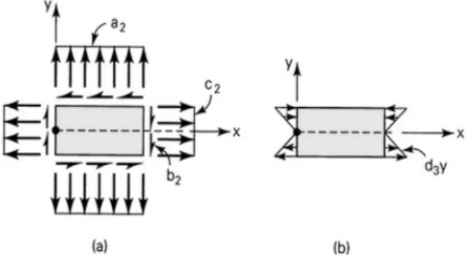
If all three stress components are constant throughout the body (Figure 2) (typical pipeline condition), it is apparent that the foregoing may be adapted to represent a uniform tensile uniaxial stress (c ≠ 0), a uniform tensile biaxial stress (c ≠ 0, a ≠ 0), or a pure shear stress (b ≠ 0). On the other hand, a polynomial of the third degree,
𝛷 = 𝑥 + 𝑥 𝑦 + 𝑥𝑦 + 𝑦 (4)
fulfills Eq. (1) and leads to stresses
𝜎 = 𝑐 𝑥 + 𝑑 𝑦 + 𝐶 𝜎 = 𝑎 𝑥 + 𝑏 𝑦 + 𝐶 ,
𝜏 = −𝑏 𝑥 − 𝑐 𝑦 + 𝐶 (5)
where 𝐶 , 𝐶 , 𝐶 are independent constants of x and y. For 𝑎 = 𝑏 = 𝑐 = 𝐶 = 𝐶 = 𝐶 = 0, these expressions reduce to
𝜎 = 𝑑 𝑦, 𝜎 = 𝜏 = 0 (6)
representing the case of pure bending of a rectangular plate. Looking close to the Eq.(3) and Eq.(6) they are well suited to model a pipeline subjected to a combination of axial, bending and torsional loadings. Figure 2 schematically shows the constants modeling the loading condition on the surface of a pipeline.
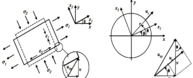
Figure 3: Stress/Strain element related to displacement in a point.
To go from stress to displacement, collected from DSPI method, it is necessary to calculate
𝑢 = ∫ 𝜀 𝑑𝑥 = 𝑥 and 𝑣 = ∫ 𝜀 𝑑𝑦 = 𝑦 (7)
and according to ur=u cosè +𝑣sinè, from Figure 3,
𝑢 = (𝑐𝑜𝑠 θ − 𝜈𝑠𝑖𝑛 θ)𝜎 + (𝑠𝑖𝑛 θ − 𝜈𝑐𝑜𝑠 θ)𝜎 + (𝑠𝑖𝑛𝜃𝑐𝑜𝑠𝜃)𝜏 + 𝑇 𝑐𝑜𝑠𝜃 + 𝑇 𝑠𝑖𝑛𝜃 (8)
where E and G represent Young's and shear modulus respectively for the pipeline material. 𝑇 and 𝑇 represent translation components that are radius independent. Now substituting Eq. (3) and Eq. (5) into equation Eq. (8), we obtain Eq. (9) that models the radial displacement close to the indentation print,
𝑢 = [𝑐𝑜𝑠 𝜃 − (2 + 3𝜈)𝑠𝑖𝑛 𝜃𝑐𝑜𝑠𝜃]𝑐 + [−(𝜈)𝑠𝑖𝑛 𝜃 + 𝑠𝑖𝑛𝜃𝑐𝑜𝑠 𝜃]𝑑 + [𝑠𝑖𝑛 𝜃 − (2 + 3𝜈) 𝑐𝑜𝑠 𝜃𝑠𝑖𝑛𝜃]𝑏 + [−(𝜈)𝑐𝑜𝑠 𝜃 + 𝑐𝑜𝑠𝜃𝑠𝑖𝑛 𝜃]𝑎 + [𝑐𝑜𝑠 𝜃 − 𝜈𝑠𝑖𝑛 𝜃]𝑐 + [𝑠𝑖𝑛 𝜃 − 𝜈𝑐𝑜𝑠 𝜃]𝑎 + [𝑠𝑖𝑛𝜃𝑐𝑜𝑠𝜃]𝑏 + 𝑇 𝑐𝑜𝑠𝜃 +
𝑇 𝑠𝑖𝑛𝜃 (9)
This expression contains the necessary information to model axial, bending and torsional loading in a real pipeline under combined loads. It is important to point out that boundary conditions should be added to the above equations to take care of the sign and directions for the derivatives to determine the actual stress field. Some care must be taken when selecting the necessary boundary conditions.
4 LEAST SQUARE APPROACH
To determine the solution for Eq. (9), an over deterministic system for the Airy’s coefficients must be solved along with the set of equations that come from the boundary conditions for ór=0 (on the boundary of the
indenta-tion) and ôrè=0 (along symmetry lines).
Now, if we only work with displacement data, the system of equations would look like
u
re=
u
r (10)or expanding
u
re=
u
r( )3+
u
r( )2 (11)or even in a system format, 𝑢( )
( ) (𝑟, 𝜃) + 𝑢( )(𝑟, 𝜃) = ( )𝑢
𝑢( )
( ) (𝑟, 𝜃) + 𝑢( )(𝑟, 𝜃) = ( )𝑢
⋮ {𝑢( )
( ) (𝑟, 𝜃) + 𝑢( )(𝑟, 𝜃) = ( )𝑢
(12)
where ur(2)and ur(3) represent Eq. (9) for “k” collected data points from the combination of functions 𝛷 , 𝛷 . The
ure(i) terms are the measured (experimental) displacement collected around the indentation. The linear system
A
*
C
=
u
re (13)where,
A - constant matrix (data from 𝑟, 𝜃) around the indentation; C - matrix of coefficients;
𝑢 - Independent vector with the experimental data. The boundary conditions can be written as: a) ór=0 at r=R (indentation radius):
ór= 𝑎 (2 − 2𝑐𝑜𝑠 (2𝜃)) + 𝑎 𝑟(𝑐𝑜𝑠 (𝜃) − 𝑐𝑜𝑠 (3𝜃)) − 𝑏 𝑠𝑖𝑛 (2𝜃) + 𝑏 𝑟(𝑠𝑖𝑛 (𝜃) − 3𝑠𝑖𝑛 (3𝜃)) + 𝑐 (2𝑐𝑜𝑠 (2𝜃) +
2) + 𝑐 𝑟(𝑐𝑜𝑠 (𝜃) + 3𝑐𝑜𝑠 (3𝜃)) + 𝑑 𝑅(𝑠𝑖𝑛 (𝜃) + 𝑠𝑖𝑛 (3𝜃)) ) = 0 (14)
and them for the symmetry lines, b)ôrè =0 (symmetry lines),
ôrè = 𝑎 sin (2𝜃) + 𝑎 𝑟sin (2𝜃)cos (𝜃) − b cos (2𝜃) + 𝑏 𝑟( sin (𝜃)sin (2𝜃) − cos (𝜃)cos (2𝜃)) − 𝑐 sin (2𝜃) +
𝑐 𝑟(sin (𝜃)(−cos (2𝜃)) − sin (2𝜃)cos (𝜃)) − 𝑑 𝑟sin (𝜃)sin(2𝜃) = 0 (15)
An algorithm can be used to find symmetry regions on the indentation fringe pattern. Solving in the least square sense the system from Eq. (12-15) would look like:
C=
( )
A-1*ure (16)From Eq. (16) the stress function coefficients 𝑎 , 𝑎 , 𝑏 , 𝑏 , 𝑐 , 𝑐 , 𝑑 , are determined.
5 EXPERIMENTAL SETUP
A large scale bending test bench was developed to evaluate the proposed methodology Fontana et al, (2016). Two seamless pipes with a length of 12 m were used as the main structure. The pipe with a nominal diameter of 200 mm comprised the test piece, and the larger one, with nominal diameter of 250 mm, provided the counter part for the bend loading. Their ends were coupled by means of connecting rods that allow their rotations to ma-terialize a simple supported beam. A hydraulic jack and a calibrated load cell, joined to it, were used to respective-ly apprespective-ly and monitor the central load. Thus, a known amount of bending moment was applied and a reference bending stress was computed. Figure 4(a) shows a photograph of the experimental bench. The loading device and connecting rods are highlighted in this photograph to show what kind of technical solutions are adopted to gener-ate bending moments.
Eight cross-sections called as S1 to S8 were selected in the test pipe (with 200 mm diameter, right pipe in Figure 4 (a)). Considering the eight cross-sections, a pair of strain gages was installed in each diametrically oppo-site position to quantify the amount of deformation introduced in each cross-section. Therefore, a redundant evaluation of bending moment and stress was performed. A load of 37,621 ± 58 N was applied for the present experiment, producing a variable linear bending moment distribution as shown in the diagram of Figure 4(b). Circular points represent the bending stresses and moments directly computed from the strains measured with the strain gages. On the other hand, the dashed curve was calculated by using the central load measured by the loading cell. Both curves show a good agreement between them and demonstrate a triangular stress distribution along the pipe length which is coincident with a distribution for a bending device.
Figure 4. Test bench: (a) photograph showing detailed views and (b) obtained bending stress distribution.
6 PIPELINE APPLICATION
One indentation test result can be seen in Figure 5 where it shows raw (a),(b) and fitted data (c) using coeffi-cients obtained from Eq. (16) after compilations from Eq. (10-15). A bidirectional state of stress is analyzed for a 200mm bended pipe according to Figure 4. An approximately 45MPa and -20MPa stress state is represented in Figure 5 (a) as displacement data.
Figure 5: Radial displacement output from experimental data. (a) Raw unwrapped (phase) displacement data, (b)Raw pre-processed displacement. (c) calculated displacement from Airy's fitted coefficients (post-processed).
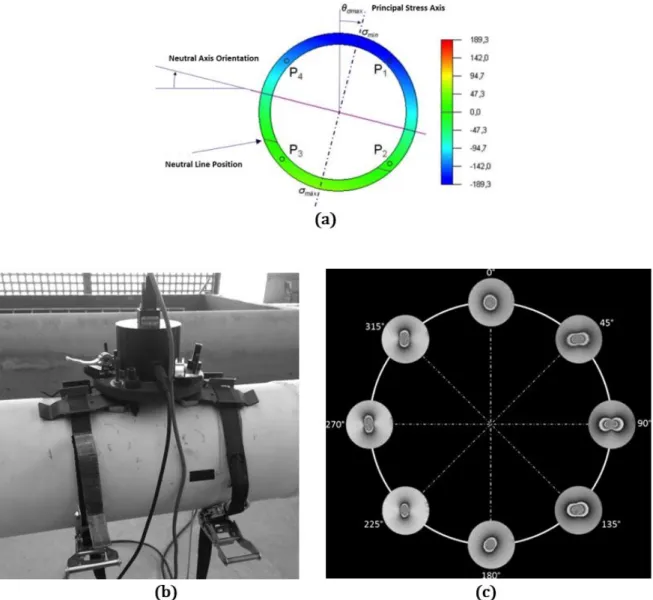
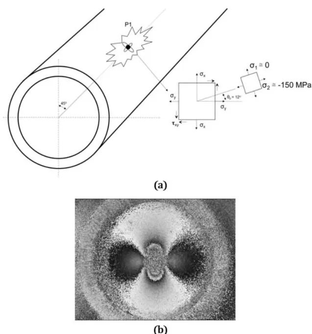
A second test was made in a point on the surface of the pipe with an expected principal stresses of 150 MPa (≈ 148MPa) and 0 (zero) close to the P1 position as seen in Figure 6(a) and (b) for the 200mm diameter tube. Figure 6(c) shows the DSPI difference phase maps obtained around the perimeter of the cross-section S4 of the loaded pipe. Figure 7(a), shows the experimental displacement data and Figure 7(b) the Airy fitted displacement field around a 2mm indentation.
Figure 6: (a) Typical bending stress distribution in a pipeline cross section under combined loads. (b) Simulated bend-ing applied to a 200mm diameter pipe. (c) Typical phase maps acquired in cross-section S4 after indentation Fontana et
Figure 8: (a) shows the principal directions and principal stresses for P1 position. (b) shows the difference phase maps measured at point P1 in the cross-section S4.
Principal stresses were easily obtained from the fitted data. Results with errors close to 10% were found for the principal stresses (≈165MPa and -10MPa). A compilation of these results in two or more cross-sections of a pipeline allows a visualization of pipe-soil behaviour.
pre-7 CONCLUSION
An interesting approach was presented to evaluate data from a bended pipe. This technique could roughly be used as a first “hot” and “cold” pre-analysis for pipeline inspections. This situation approximately models the in-teraction from pipe to ground movements. The experimental technique is based on indentation stresses super-posed to the surface of a pipe during inspections and maintenance. A radial in-plane DSPI interferometer using diffractive optics is used to collect points of interest. An algorithm using Airy’s stress function coefficients maps the radial displacement field close to the indentation. Results representing 10% to 15% error regarding the prin-cipal stresses were shown. The hybrid Airy stress fitting technique demonstrated to be adequate for a pretest analysis.
ACKNOWLEDGEMENT
The author wants to thank Eng. João Henrique R. Heinzen of Labmetro, UFSC. This work was supported from PETROBRAS grant no. 0802.0076459.12.9.
References
A. Pacheco, M. R. Viotti, C. L. N. Veiga, A. Albertazzi Jr., (2016). “Evaluation of bending stresses in pipelines by us-ing hole-drillus-ing measurements combined with interferometry,” Exp. Mech.56, 133-143 .
Albertazzi, Matias, Kapp, (2008). A radial in-plane DSPI interferometer using diffractive optics for residual stress-es mstress-esurement”. Ninth International Symposium on Laser Metrology, edited by Chenggen Quan, Anand Asundi Proc. of SPIE Vol. 7155, 715525.
ASTM E837-1, (2013). “Standard test method for determining residual stresses by the hole-drilling strain-gage method,” Annual Book of ASTM Standards. American Society for Testing and Materials.
Cavaco, M. A. M., (2011).A hybrid technique for residual stress analysis through stress function fitting. Latin American Journal of Solids and Structures (printed) v. 1, p. 259-264.
Cavaco, M. A. M., Brito, Antonio, (2015)”A Hybrid ESPI Technique for Residual Stress Analysis in Ducts”. 23rd ABCM International Congress of Mechanical Engineering, Rio de Janeiro, RJ, Brazil, Dec. 6-1.
Fontana, F., M.R.Viotti, A.Albertazzi Jr., (2016).Bending Stress Determination in a Pipe Test Bench Using DSPI Combined with Instrumented Indentation. Experimental Me-chanics, Society for Experimental Mechanics .
Fontana, Filipe, (2015).Measurements of Bending Moment of Pipes Using Instrumented Indentation Combined with Radial Interferometer, Master Dissertation, UFSC.
Freire, J. L. F. et al. (2009).Pipe Integrity (in Portuguese). Pipeline Engineering. Rio de Janeiro, Brasil: ABCM.
Muskhelishvili NI., (1963). Some basic problems of the mathematical theory of elasticity, 4th ed. Groningen, Neth-erlands: P. Noordhoff.
Timoshenko and Goodier, (1970).Theory of Elasticity. Third Edition. McGraw Hill.
Viotti, M. R. and Albertazzi Jr., A., (2013). “Compact sensor combining DSPI and the hole-drilling technique to measure non-uniform residual stress fields,” Opt. Eng. 52, 101905 .
Viotti, M. R., Albertazzi Jr., A., and Kapp, W., (2008). “Experimental comparison between a portable DSPI device with diffractive optical element and a hole drilling strain gage combined system,” Opt. Lasers Eng. 46, 835-841.