Development of a Robotic Prototype System for the
Preparation and Partition of Radioactive Products
Gabriela Guevara
1, José Lima
1,2, Paulo Leitão
1,3, Maria do Carmo Baptista
4 1 Polytechnic Institute of Bragança, Campus Sta Apolónia, Apartado 1134, 5301-857 Bragança, PortugalEmail: [email protected], [email protected], [email protected]
2 INESC TEC (formerly INESC PORTO) - Robotics and Intelligent Systems, Rua Dr. Roberto Frias, 4200-465 Porto, Portugal 3 LIACC - Artificial Intelligence and Computer Science Laboratory, Rua Dr. Roberto Frias, 4200- 465 Porto, Portugal
4 Medical Physics Department, Dr. Campos Costa - Consultório T.C. SA., Rua de Avis 13, 4050-075 Porto, Portugal Email: [email protected]
Abstract- The ionizing radiation is used in the nuclear medicine field during the execution of diagnosis exams. The continuous exposure of humans to the radiation may cause organs and tissues damage, being its severity dependent of the quantity of the radiation and the exposure time. The main objective of this work is to design a virtual environment to carry out the simulation of the several stages for the preparation of radioactive products based on the use of a robotic arm. In this work, the V-REP robotic simulation tool was used for the specification and development of the manipulation processes, without the need to consider the real manipulator, being timely and costly efficient. During this study, the preparation process of the dosages in the diagnostic exams was analyzed, being posteriorly translated into mechanical processes for a better perception. The materials and equipment needed were designed as virtual 3D models and posteriorly imported into the V-REP simulation platform in order to be distributed and programmed to achieve a closer approximation to reality.
I. INTRODUCTION
The medical imaging is an area of knowledge with continuous technological innovation, applying new techniques for the medical diagnosis in order to provide an image of the anatomy of the human body and its functions [1]. Nowadays, diagnosis tests are used to allow the acquisition of images with detailed information of a particular organ. The scintigraphy is one of the diagnosis tests that detects with some precision when a certain part of the body has a change in the metabolism [2].
In the field of the nuclear medicine, the minimally invasive diagnosis requires intravenous administration of radiopharmaceutical components [3]. The preparation of the radioactive doses is currently performed by nuclear medicine specialists [4]. During the preparation of the radioactive doses, protection techniques are used to minimize the exposure of these technicians to the ionizing radiation [5]. However, the continuous exposure to the radiation may cause the damage in the organs and tissues of technicians.
According to NUMDAB (Nuclear Medicine Database), there are 1348 nuclear medicine institutions in the world, of which 1157 are active. Actually, half million PET (Positron Emission Tomography) and PET-CT (Computed
Tomography) annual examinations are registered in the world [6]. In Portugal, data shows an average of 20 exams per day.
The use of manipulator robots allow to automatize repetitive operations, being advantageously deployed in several industrial domains. Their intrinsic properties will bring important benefits, namely in terms of productivity, flexibility, quality and possibility to remove the operators from hostile environments [7]. New applications for robots are emerging in the medical sector, considering the general requirements related to the safety of medical electrical equipment and systems. Medical applications cover invasive and non-invasive procedures, such as surgery, rehabilitation therapy, imaging, diagnosis and treatment [8]. As examples, the DaVinci system is used to perform routine and complex surgeries, such as laparoscopy [9], and the Walischmiller Engineering manipulator system is used in inaccessible areas to humans, mainly in the nuclear and chemical industries, e.g., hot cells and nuclear power plant decommissioning [10]. Master-slave manipulator systems are used for the remote handling of hazardous materials in nuclear medicine, biotechnology and nuclear technology [11]. As example, robots are used to reduce the radioactive dose levels to which workers are exposed during the decommissioning processes [12]. Other example is related to the use of an automatic system to execute the fractioning and the calibration of the radiopharmaceutical in syringes and vials, with the possibility to sterilize them through an autoclave. This equipment has an automatic dispensing system to fill the vial/syringe with the radioactive product (e.g. BBST Series) [13].
The main objective of this work is to minimize the exposure levels of radiation absorbed by the nuclear medicine technicians through the development of a robotized system with the capability of execute the elution and partition of radioactive products in an efficient way. In this study, a robotic simulator platform was used since it allows a rapid proof of concept by modelling and testing different alternative solutions without the need to use the physical robot manipulator, saving costs and time.
motion planning, allowing the pre-evaluation of new concepts and algorithms. The repeatability of experiments, the avoidance of expensive robotic hardware, combined with the increasing computational power, made simulations more and more important in the last decade [14]. For this purpose, this work considers a robotic prototype system using a virtual platform. A high diversity of robotic simulators is currently available, such as Gazebo, ODE, Bullet, OpenRave, V-REP, XDE and Blender [15]. In this study, the V-REP simulator was selected to develop the virtual platform since it addresses several important aspects, such as advanced functionalities, tutorials, active community and API (Application Protocol Interface) to interconnect other tools.
This paper is organized as follows: Section II presents the case study to be analyzed in this paper and Section III formalizes the system architecture for the robotic system. Section IV describes the development of the robotic prototype using the V-REP simulation platform and Section V describes the system operation and analyses the obtained results. At last, section VI rounds up the paper with the conclusions and points out the future work.
II. CASE STUDY: PREPARATION AND PARTITION OF RADIOACTIVE PRODUCTS
The execution of the elution and partition processes of radioactive products are made by nuclear medicine technicians. The technicians must possess appropriate skills and know the risks involved in this type of work.
The process in study is divided in several phases: the first phase is the radioisotope elution, the second one is the partition of the patient doses, and in some cases the intermediary phase is considered, including the addition of a pharmaceutical component into the radioactive solution [16]. A.First Phase
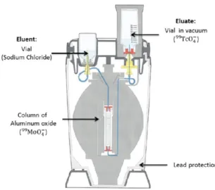
Initially, the radionuclide generator produces the radioisotope (in this case the technetium 99mTc, also named sodium pertecnetato). The technetium is continuously produced from the radioactive molybdenum (99Mo). The generator allows the collection of the technetium in an injectable solution. The collection of the radioactive solution is performed using a vacuum vial that is connected with the needle fixed in the molybdenum/technetium generator, as illustrated in Fig. 1.
The quantity of the extracted technetium depends of the residue quantity of molybdenum and the time since the last extraction. It cannot be despised the radioactive decay of the radioactive products, which is given by A=A0e-t, in which is the disintegration (decay) constant, having a characteristic value for every radionuclide, A0 is the activity at time t=0 and A is the activity at time t [18].
After the first radionuclide elution, the vial is transferred to the dose calibrator, which will execute the measurement of the radioactive activity of the eluato.
Fig. 1. Execution of the first phase: preparation of the elution of the technetium (99mTc) from the radioactive molybdenum (99Mo).
B.Second Phase
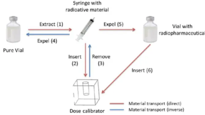
The second phase (also known as partition process), illustrated in Fig. 2, begins after the end of the first phase and is related to the execution of the partition of the radioactive solution by the total number of patients scheduled in that day.
Fig. 2. Execution of the second phase: scheme of the partition process performed by the successive steps for the obtainment of the desired dose.
The quantity of the solution partition is different for each patient, since the needs and characteristics of each patient are different. The number of scheduled patients in one day depends of the quantity of eluted solution that can be produced in that day.
C.Intermediary Phase
will be injected in the respective patient. Fig. 3 shows each step made during the intermediary phase.
Fig. 3. Execution or the intermediary phase.
III. SYSTEM ARCHITECTURE
The description of the processes made in the nuclear medicine laboratories clearly shows the quantity of radiation absorbed by the technicians during the execution of these phases. Considering the statistical data and the occupational dosimetry applied in the nuclear services, it is important to develop robotic systems that handle the radioactive products aiming to minimize the radiation exposure of the nuclear medicine technicians.
For this purpose, an integrated robotic system was build, made of several components, as illustrated in Fig. 4. The first component is the SinaDix application that aims to constitute a simple, friendly and intuitive user interface, where technicians can access after introducing their credentials. The application has several buttons, some to start the elution or partition processes, and others to introduce the parameters of the process, to access the database, to make the choice of the material (type of envase or the selection of the radionuclide) that will be used, among others. This application also makes the calculus of the radiation decay of the selected radionuclide, which means that the user can observe the loss of the radiation activity over the time.
Fig. 4. System architecture for the robotic system.
The SinaDix application accesses the radionuclide activity data by interfacing the Curiementor3 dose calibrator through a RS232 connection. The radiation activity values will be
stored in the MySQL database, which is performing a relation with the exams schedule program in the RIS (Radiology Information System) database. The application screen shows the patients’ data and the dose of radiation that they will need in the diagnosis exams. With this information the technicians know what processes are made and calculate the needs to be executed for the obtainment of the exact dose volume.
The RoboDix application consists of the robotic system used to manipulate the radioactive devices during the preparation of the doses. For this purpose, a virtual robotic environment using the V-REP simulator is used, which communicates with the SinaDix application through an UDP (User Datagram Protocol) interface. This interface allows to exchange information related to the name of the phase that will be executed and the associated parameters.
The rest of the paper will detail the RoboDix application, by describing the creation of the robotic simulation environment to replicate the real processes, namely the elaboration of the 3D models for the equipment and the programming of the manipulator. The V-rep simulator is known for several features, among them the wide range of stable options and properties included in the dynamic behavior of a body, as well as the powerful and flexible inverse kinematics calculation module for real robots approaching the simulation to reality [17].
IV. ROBOTIC SIMULATION PLATFORM
The RoboDix application is composed by a scene that represents the room where the elution and partition processes are executed and includes the materials and equipment for the execution of the processes. Fig. 5 illustrates the layout of the environment used for the execution of the several phases.
Fig. 5. Distribution of the objects around the scene.
This layout optimizes the free space in the room, as well the movements of the manipulator.
A.Design of the 3D Models
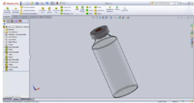
laboratory as auxiliary syringe/vial support. For the elution process, the manipulator will transport the "Adaptor" (with the syringe or vial) from the table to the calibration cylinder, that is the responsible for the radioactive activity reading. A component of great importance is the vial, which has a crucial role in the transportation and containment of the radioactive material. The model used in this work was a vacuum vial with 20 ml of capacity, which 3D model is represented in Fig. 6 with their respective dimensions.
Fig. 6. Virtual model of the 20 ml vial.
Fig. 7 illustrates the 10 ml syringe used to transport the radioactive product.
Fig. 7. Virtual model of the 10 ml syringe.
In some situations, the manipulator needs auxiliary equipment to perform some complex processes, e.g., the extraction of the liquid hosted in the syringe. For this purpose, this auxiliary device was also designed in SolidWorks, being composed by the syringe support and the syringe/vial support. The syringe/vial support can be observed in Fig. 8.
Fig. 8. Virtual model of the syringe/vial support.
The syringe/vial support will be used in the second phase allowing the easy and safe extraction of the syringe content by the robotic manipulator. This equipment fixes the vial and
the syringe in the correct position and will perform the extraction process.
B.Programing the robotic system
The selected manipulator is a "7 DoF Manipulator", illustrated in Fig. 9, which is available from the V-REP libraries. The manipulator is positioned in the center of the scene and the rest of the objects are distributed around it.
Fig. 9. Manipulator used in the robotic simulation system.
The joints allow the motion of the robot but for their good performance it is necessary the definition of constraints. Each joint has its properties that can be the rotation degrees for the rotate joint or the distance for the cylindrical joint. The most used joint mode is the "joint is in torque/force mode" [18]. When the joint torque/force mode is used, the user can change the joint velocity, the maximum torque/force applied and the maximum velocity.
The dynamic model of the manipulator joints are in the inverse kinematics mode. The inverse kinematics is related to find the required joint variables to achieve a specified end effector position and orientation [19]. The application of the inverse kinematics requires the creation of the inverse kinematics group where it is defined the inverse kinematics properties, such as the maximum number of iterations, the joint limits and the calculation method.
The "pseudo inverse" is the fastest calculation method but can be unstable when the target and tip lie too far apart, when a kinematic chain is over constrained or when the mechanism is close to a singular configuration or the target is out of reach. The Damped Least Squares (DLS) method is slower but more stable since it is a damped resolution method (note that the damping factor can be specified). The inverse kinematics groups were created considering both methods allowing to use firstly the pseudo inverse method to calculate the position and orientation of the "tip", and in alternative the DLS method if the previous one fails [17].
The V-REP simulator can be programmed in many languages, like C/C++, Python, Java, Lua, Matlab, Octave or Urbi. In this work, the Lua synopsis was used to program the trajectories of the manipulator to perform the required tasks.
position and orientation of the reference point to calculate the values of rotation for each joint.
Fig. 10. Flowchart to execute a trajectory illustrated for the elution process. The calculation of the inverse kinematics requires to know two points: the starting point (i.e. the reference point named "tip") and the target point (in this case P0). The difference between the "tip" and the target point will be the distance that the robotic arm has to go through to get its new position. The implementation of the inverse kinematics function should be written as a Lua script, which may use the dynamic objects defined in the virtual platform. The Lua function that passes an object to a variable is:
handle=simGetObjectHandle("gripper")
where the gripper represents the created object (i.e. the dynamic object) in the platform and handle is the name of the variable calling the object. When a platform object is called, the object parameters can be changed or consulted applying API functions in the Lua script. The auxiliary Lua functions for the acquisition of the position and orientation of the object, e.g., the "tip", are:
simGetObjectPosition(tip,-1) simGetObjectOrientation(tip,-1)
where the input parameter “-1” represents the calculus of the object position in the simulation world. The output of the functions are two vectors, one for the position (x,y,z) and the other for the values of the orientation (,,).
When these objects are called and the position and orientation of the "tip" and the new point are known, the inverse kinematics function is called. The Lua script for the inverse kinematics is composed by many sub-functions of the Lua synopsis as illustrated in the bellow pseudo-code. The function reads the current position and orientation of the robot and calculates the rotation values of the joints that will be needed for the relocation of the manipulator for the new point.
for i=1 to 7 do
currentJ[i]=simGetJointPosition( ...jHandles[i])
endfor
maxVariationAllowed=maxJointVelocity* ...simGetSimulationTimeStep()
for i=1 to 7 do
delta=desiredJ[i]-currentJ[i]
if math.abs(delta) > maxVariationAllowed then
delta=maxVariationAllowed*delta/ ...math.abs(delta)
endif
simSetJointPosition(jHandles[i], ...currentJ[i]+delta)
endfor
posTip=simGetObjectPosition(tip,-1) simSetObjectPosition(target,-1,posTip) oriTip=simGetObjectOrientation(tip,-1) simSetObjectOrientation(target,-1,oriTip)
The first cycle creates a vector with the rotation degrees of the joints. The second cycle changes the rotation of the joints by using the current rotation of each joint plus the degrees needed for the desired position. The last functions are used to ensure that the "tip" is in the correct position and orientation.
When the manipulator reaches the P0 position the simulator waits for a message from the SinaDix application sent by the user (in this case, it was used the "Elution" message). After receiving the message, the manipulator decomposes the overall trajectory into partial movements between points. In an iterative manner, the manipulator will read the next point, calculates the inverse kinematics (as described before) and moves the arm to the next point. The complete trajectory will be finished when the manipulator will reach the final point.
After the definition of the joints properties and the development of the Lua script, the robot can be able to move effectively all its joints. Fig. 11 shows the manipulator grasping the "Adaptor".
Fig. 11. Manipulator motion grasping the “Adaptor”.
It is important to remember that the manipulator is fixed to the ground, which reduces its amount and type of movements.
V. SYSTEM OPERATION
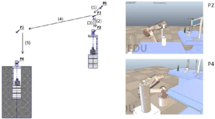
Fig. 12. Execution of the elution process (only one way).
The mechanical schema is an easy representation of the trajectories for the elution process. The manipulator always begins and ends the execution of a process (elution or partition phase) in the rest position.
During this work, some hypotheses for the design and distribution of equipment in the simulator platform were applied. In some cases, to avoid the collision between the robot and the objects, the right distribution of the target points is not enough. When the simulator executes the calculus of the joints rotation angles using the inverse kinematics, the obtained result is not unique. This means that it is necessary to increase the constraints around the robot until the manipulator performance be the more appropriate one.
The developed robotic system was intensively tested using the simulator environment, allowing the adjustment and correction of errors (e.g., possible collisions during the movements). Particularly, the most practical and efficient trajectories for the execution of the manipulation tasks were defined. At the end, the designed robotic system at the virtual environment was validated and serves as a proof-of-concept.
The next step is the migration from the virtual robotic platform to the real physical world, where a real manipulator will be used to perform the manipulation tasks during the execution of the elution and partition processes. This task is simplified since the model was already tested and validated in the V-REP environment, being only necessary the translation of the programming code to the real manipulator.
VI. CONCLUSIONS
Nowadays, a significant number of diagnostic exams using radioactive products are daily performed. The continuous exposure of the skilled technicians in radioactive environments may cause the damage of the human cells and the consequences can be the serious diseases in the future.
The main objective of this work was the development of a robotic prototype solution based on simulation that minimizes the radiation exposure of technicians in the nuclear medicine laboratories. The repeatability, precision and radioactive resistance provided by robots make them the ideal for this kind of dangerous environments. Using the V-REP robotic simulator software, it was possible to create a virtual robotic environment that emulates the real one and simulate the robot movements in a safe environment.
The case study under analysis, comprising the preparation of radioactive doses, was modelled in V-REP, and a robotic system was specified and programmed to perform the manipulation tasks in an effective and safe manner. The robotic model was intensively simulated allowing the correction of errors and optimization of some trajectories, constituting a proof-of-concept for the designed solution validating all the developed components.
Future work is related to study other radioactive processes executed in the nuclear medicine departments and to migrate from the simulation platform to the real physical world.
REFERENCES
[1] P. Suetens, “Fundamentals of Medical Imaging”, 2nd ed., Cambridge University Press, New York, United States, 2009.
[2] G. Saha, “Basic of PET Imaging - Physics, Chemistry, and Regulations”, 2nd ed., Springer, 2010.
[3] J. Stauss et al., “Guidelines for 18F-FDG PET and PET-CT Imaging in Paediatric Oncology”, European Journal of Nuclear Medicine and Molecular Imaging, 35(8), Springer, pp. 1581-1588, 2008.
[4] A. Carnicer, et al., “Hand Exposure in Diagnostic Nuclear Medicine with 18F- and 99mTc-labelled Radiopharmaceuticals - Results of the ORAMED Project”, Intern. Workshop on Optimization of Radiation Protection of Medical Staff, 46(11), Elsevier, pp. 1277-1282, 2011. [5] G. Hammer, U. Scheidemann-Wesp, F. Samkange-Zeeb, H. Wicke, K.
Neriishi, M. Blettner, “Occupational Exposure to Low Doses of Ionizing Radiation and Cataract Development: a Systematic Literature Review and Perspectives on Future Studies”, Radiat Environ Biophys 52(3), pp. 303-319, 2013.
[6] NUMDAB, International Atomic Energy Agency (IAEA), http://nucmedicine.iaea.org/default.asp (accessed on 14/11/2014). [7] M. Xie, Fundamentals of Robotics, World Scientific Publishing, 2003. [8] International Electrotechnical Commission, “e-tech - International
Standards Vital for Medical Robots Safety”, May 2013, http://www.iec.ch/etech/2013/etech_0513/tech-1.htm (accessed on 20/11/2014).
[9] da Vinci Surgery, Intuitive Surgical, http://www.davincisurgery.com/, (accessed on 21/11/2014).
[10] Walischmiller Engineering, “Master-Slave Manipulator System HWM A100”,
http://www.hwm.com/12-1-Master-Slave+Manipulator+Typen+A100.html (accessed on 20/11/2014). [11] H. Bässler and F. Lehmann, “Containment Technology: Progress in the
Pharmaceutical and Food Processing Industry”, Springer, 2013. [12] M. Bakari, K. Zied and D. Seward, “Development of a Multi-Arm
Mobile Robot for Nuclear Decommissioning Tasks”, International Journal of Advanced Robotic Systems, 4(4), pp. 387-406, 2007. [13] Comercer, “TALIA Series - Class A Laminar Flow Hot Cell for
Dispensing Systems”, https://www.comecer.com/nuclear-
medicine/radiochemistry-pet-cyclotron-conventional-nuclear-medicine/hot-cells/class-a-laminar-flow-cells-mod-bbst/ (accessed on 10/01/2015).
[14] A. Roennau, F. Sutter, G. Heppner, J. Oberlaender, R. Dillmann, “Evaluation of Physics Engines for Robotic Simulations with a Special Focus on the Dynamics of Walking Robots”, Proceedings of the 16th International Conference on Advanced Robotics (ICAR), pp. 1-7, 2013. [15] S. Ivaldi, J. Peters, V. Padois and F. Nori, “Tools for Simulating Humanoid Robot Dynamics: a Survey Based on User Feedback”, IEEE-RAS International Conference on Humanoid Robots, 2014. [16] IAEA Human Health Campus, “Virtual Course in Radiopharmacy”,
http://nucleus.iaea.org/HHW/Radiopharmacy/VirRad/index.html (accessed on 20/11/2014).
[17] V-REP, Coppelia Robotics, http://coppeliarobotics.com/ (accessed on 18/11/2014).
[18] D. Halliday, R. Resnick and J. Walker, “Fundamentals of Physics”, John Wiley & Sons, 10th ed., 2013.
[19] G. Singh, J. Claassens, “An Analytical Solution for the Inverse Kinematics of a Redundant 7DoF Manipulator with Link Offsets”, IEEE/RSJ Int. Conf. on Intel. Robots and Syst., pp. 2976-2982, 2010.