E-legging for monitoring the human locomotion patterns
6
0
0
Texto
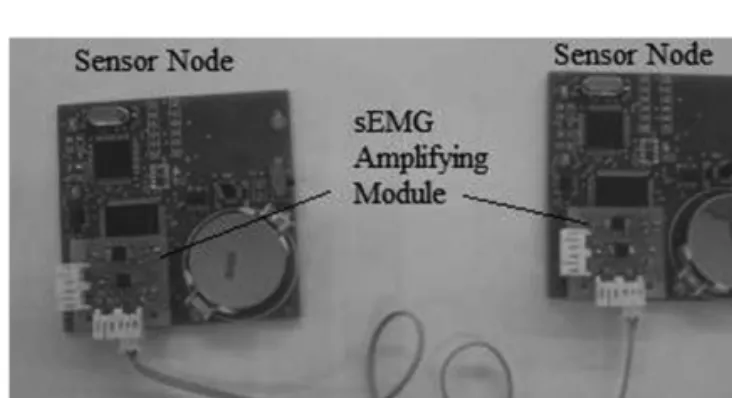
(2) અ. 【T:】Edianserver/日本繊維機械学会/Journal of Textile Engineering/Vo. 59, No. 6/□ 12-11S. 校. CATARINO André, ROCHA Ana Maria, ABREU Maria José, DEROGARIAN Fardin, DA SILVA José, FERREIRA João, TAVARES Vitor, CORREIA Miguel, DIAS Ruben. electromyography (sEMG) of several muscles (quadriceps femoris,. accurate time alignment. The CPM gathers information from all. biceps femoris, tibialis anterior and gastrocnemius medialis). The. the nodes, performs some local processing, and sends aggregated. sensors communicate by means of sensor nodes (SN) to the central. data, immediately or later, via a wireless link to a personal. processing module (CPM), which on its turn sends the information. computer for further processing.. by wireless communication. The analogue signals measured with. The communication among SN is performed over a single signal. the sensors are immediately converted to digital signals in the. line. Also, as wireless-based systems are prone to be affected by. sensor nodes (SN), in order to reduce as much as possible the. interferences, in order to improve data communication reliability. presence of artifacts. These sensor nodes (SN) are placed nearby. the CPM module is also equipped with a USB port and a MicroSD. the sensors and connected to them using special conductive textile. card. yarns, made of polyamide filaments covered with silver. The. communication fails. Fig. 2 illustrates two sensor nodes developed. central processing module (CPM) is placed on the waist, while the. for this project, connected through hard wire during the test period.. sensor nodes are distributed on the garment (Fig. 1). These sensor. This first version boards had the approximate dimensions of 50. nodes share paths between them with the purpose of having. mm×50 mm and a height of 25 mm. The final version of these. alternative paths to send the data collected by the sensors. Using. sensor nodes will include all the hardware in one single card, with. this approach, the system can select the most favorable path or. 30×30 mm and 5 to 8 mm height. The weight will be of 30 g.. to. save. and. transfer. data. whenever. the. wireless. have alternatives in case of damage on one of the paths. It is. Energy efficiency and integration of systems are considered. important to note that the sensor nodes (SN) do not communicate. fundamental milestones for the proposed body-area network. The. wirelessly with the central processing module (CPM), rather than. system should work for long periods of time, especially during. communicate through wires, in this case textile conductive wires. prolonged monitoring. Thus, a reactive, energy-efficient routing. that build these paths.. protocol, described in [3], was developed and adopted for the. The prototype sensor network under development comprises one CPM and eight SN, although capable to be extended to 255 SNs.. network data layer. This protocol does not require each node to possess global information about the network, but still ensures that. It was decided to integrate each sEMG and inertial signals associated with the same limb segment in one SN for a more. Fig. 1. Interconnection topology of the mesh sensors network.. Fig. 2. Two sensor node prototypes connected to each other.. 16 MHz. Network Interface (FPGA) TX. Line 1 Line 2 Line 3 Line 4. Line Driver. (SPI1). (SPI1). Control. Line Control. (INT). (INT). RX Clock. UC PIC24FJ64GA104. SPI Port. (CLK) (ADC(10 bit). EMG Fig. 3. (SPI2). (INT). (I2C). Inertial sensors. Block diagram of the sensor node prototype.. 154. Vol.59_No.6_.mcd. Page 32. 13/12/18 08:39. v6.20.
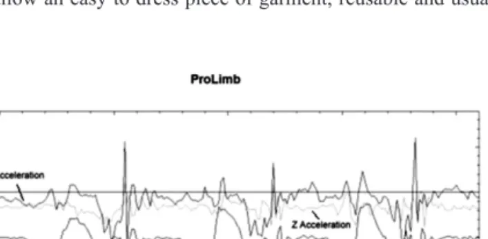
(3) અ. 【T:】Edianserver/日本繊維機械学会/Journal of Textile Engineering/Vo. 59, No. 6/□ 12-11S. 校. Journal of Textile Engineering (2013), Vol. 59, No. 6, 153 - 158. all data communication uses minimum cost paths. It also handles. methods for cleaning and maintenance.. link and node failures gracefully. Simulation results show that this. Regarding the sensors to be embedded in the E-legging, the. protocol provides better performance than the standard minimum-. biopotential parameters are the ones that are more successful in. cost forwarding protocol [4]. Results also indicate higher. terms of reliability. For that reason sEMG electrodes were. throughput and less energy dissipation, leading to increased. embedded in the knitted fabric, making use of the technology. network lifetime. Fig. 2 illustrates the sensor nodes.. available on weft knitting. Although several yarns exist that. The first hardware prototypes for the SN and the CPM have. present good electrical properties, specific physical characteristics. been designed and fabricated (Fig. 3), for proof of concept. are required in order to being used in textile production. purposes. Fig. 3 shows the block diagram of a sensor node (SN).. equipment : rigidity, friction and mechanical resistance. Yarns. The network interface (physical and data link layer) is. must bent easily, present a low dynamic friction coefficient, and. implemented in a low-power FPGA (Actel AGLN125) operating at. have an acceptable mechanical resistance, since they will be. 16 MHz. The physical layer employs baseband communication. submitted to high traction forces during the knitting production. using the NRZI (non-return-to-zero, inverted) line code, with 0 V. process.. and 1.5 V signal levels. Future plans include the miniaturization of the sensor node, so that it can be attached to the garment.. As mentioned above, previous research [6] has shown that it is possible to measure electric potentials using electrically conductive. The PIC24 16-bit microcontroller in the SN implements the. fibers or yarns instead of conventional electrodes, being possible to. routing protocol, performs sEMG signal acquisition using the. measure biopotentials using dry or wet textile based electrodes.. built-in 10-bit A/D converter, and uses the I2C bus to acquire. Regarding the raw material to be used as conductive element,. acceleration and angular movement data.. yarns made of pure copper present excellent electrical conductivity. Fig. 4 shows an example of accelerometer signal captured with. and are cost effective, however the resulting fabric, if possible to. this setup while the test subject executed three steps, and. be produced, usually results rigid and uncomfortable. Moreover,. transferred from the CPM to a PC through Bluetooth.. these yarns break during production or cut the other yarns built in. Signal processing methods will include the real-time calculation. the surrounding structure, which constitute the support of the. of the average rectified value (AVR) and standard root mean. electrodes. Thus, these yarns may not be used directly in knitted. square of sEMG signals, providing the onset and offset of muscle. fabric, unless they are covered with a smoother surface that at the. activity above a customized preconfigured threshold. Further. same time offers a mechanical behavior more adjusted to weft. developments are taking place to include methods to characterize. knitting.. muscle fiber properties and muscle fatigue, which are relevant for rehabilitation and training [5].. In order to successfully produce fabrics with conductive yarns, and particularly to build textile sensors, namely sEMG electrodes, two types presenting relatively good electrical properties have been. 3.. Textile based sensors in the E-legging. used : A) spun yarns with a mixture of polyester, and stainless steel fibers with linear resistances of 350 Ohm/m ; B) and yarns made. A wearable garment meant to be comfortable implies an adequate combination of materials, compression effect and. with twisted filaments, each one a polymeric filament covered with silver with linear resistances of about 30-40 Ohm/m.. preferably with electronic components incorporated in the textile. The fundamental assumptions of this project demand for a fabric. and interconnected with data and power tracks, if possible made. made from weft knit due to its inherent properties, such as. with conductive yarns embedded in the fabrics. This solution. elasticity, body fit and comfort. There are weft knitting machines. would allow an easy to dress piece of garment, reusable and usual. that allow producing fabrics specially conceived for body size, being the seamless technology one of the most used ones. The capabilities of modern textile machines also permit designing textile-based electrodes with the most adequate shape, as well choosing the most convenient position. This is achieved by selecting a proper structure, and by inserting and removing the conductive yarns in the fabric, by exchanging with a base yarn or simply by adding the conductive yarn to the base yarn already being used in the fabric’s production. The knitting machine used has one single needle system, gauge E28, it is a full jacquard machine with eight feeding and cam systems. The yarns are supplied into the knitting zone with storage feeders and electronic. Fig. 4. Accelerometer signal captured by the sensor node. feeders whenever elastane is used. The yarns are selected through. prototype, corresponding to muscle activity during 3 steps.. one of seven yarn guides of each stripper and cut when not needed.. 155. Vol.59_No.6_.mcd. Page 33. 13/12/18 08:39. v6.20.
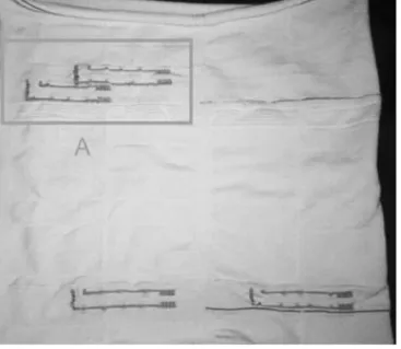
(4) અ. 【T:】Edianserver/日本繊維機械学会/Journal of Textile Engineering/Vo. 59, No. 6/□ 12-11S. 校. CATARINO André, ROCHA Ana Maria, ABREU Maria José, DEROGARIAN Fardin, DA SILVA José, FERREIRA João, TAVARES Vitor, CORREIA Miguel, DIAS Ruben. electrodes and conducting tracks for all the sensor nodes, a suitable but complex design of the tracks is necessary in order to knit the yarns without crossing each other. This is where the capabilities of the production machines assume a critical importance, justifying Fig. 5. Detail of an electrode (left side) and its track for signal transport into the sensor node (center and right).. the technology that was adopted. Our machine is capable of drawing a pattern where the conductive yarn is carefully selected to be inserted in specific places, thus guarantying that the tracks will not intersect. Other issues will then rise, like isolating the. Fig. 5 illustrates an electrode and conductive track, both embedded in the knitted fabric. The electrode can be seen in far. tracks. This matter shall be addressed in a next stage of this project.. left side of Fig. 5 and presents an area of 1×1 cm2, knitted with a. Fig. 8 illustrates a version of the program used to produce the. special structure that improves the contact with skin and thus. tracks and electrodes. Although the resulting tube represents a 3D. reduces the skin to electrode impedance. The interconnection line. shape, it is necessary to transform the legging into a 2D shape,. comprises six consecutive rows of the same conductive yarn. The. considering that the first column of pixels at the left side of the. vertical line on the far right side of Fig. 5 is also made with six. drawing will be the same as the column that is more far away, on. columns of conductive yarn.. the right side. The number of columns in the drawing represents. Fig. 6 illustrates how the electrodes are presented in a finished. the number of needles in the knitting machine, in this case 1152. piece of garment and a Fig. 7 shows the resulting waveform for a. needles. The letter A represents an area where two pairs of. sEMG signal captured with these electrodes.. electrodes are knitted, and B shows where the hip will be. The two. Comparing to the signals obtained with conventional electrodes. coarser light grey vertical lines that are nearby B are the place. it was observed that these signals present some additional noise,. where the tube will be cut and later sewed in order to produce the. which can be reduced by improving the electrode ― skin contact. two legs. Several lines are displayed in Fig. 8. Regarding the. impedance and afterwards with signal filtering. There is a similar. horizontal stripes, the thinner ones represent fixed distances in. behavior between the signal patterns obtained with conventional. order to better place the electrodes during design and also as. and textile electrodes [6].. orientation for the user. The coarser horizontal bands coincide with. In order to develop a legging-like garment, with embedded. Fig. 6. the regions where the electrodes are knitted, which demand for a. sEMG electrodes placed in a legging and the obtained myoelectric signal.. Fig. 7. sEMG signal obtained with the electrodes presented in Fig. 6.. Fig. 8. Drawing of the e-legging, using the knitting machineʼ s CAD system.. 156. Vol.59_No.6_.mcd. Page 34. 13/12/18 08:39. v6.20.
(5) અ. 【T:】Edianserver/日本繊維機械学会/Journal of Textile Engineering/Vo. 59, No. 6/□ 12-11S. 校. Journal of Textile Engineering (2013), Vol. 59, No. 6, 153 - 158. Table 1 Yarn. Thickness and density of onion sheet. Relaxed. Stretched 50%. Ω/ cm. nH/ cm. Ω/ cm. nH/ cm. 1. 0.65. 16.4. 0.47. 6.68. 2. 6.76. 35. 4.43. 33. in order to obtain a suitable communication frequency. The yarn impedance together with the circuits output and input capacitances create a π interconnection, whose step response presents a rise time given by tr≈2.2RC+0.6 LC A mesh like network is being used for the interconnected sensor nodes. The worst case interconnection impedance is that of the path between the central processing unit (CPM), to be placed in the user’s belt, and one of the SN placed in the shank. Considering a Fig. 9. Fabric produced based on the drawing made on the knitting machineʼs CAD system.. more elastic and stronger structure, able to better sustain the. voltage defined signal, it was found that each track should be made with a minimum of 4 yarns to ensure a transmission frequency of 10 MHz with rise and falling times shorter than 12 ns. Nevertheless, tracks with six yarns were adopted.. electrodes in place. The vertical lines are made with different. The interconnections reliability raises two issues. One concerns. colors and are used both to provide an orientation to the user for a. the yarn impedance variability and the other the quality of the. correct positioning of the electrodes. Fig. 9 illustrates the resulting. interface between yarn and electronics. A specific interconnections. fabric, where one can observe the electrodes and corresponding. test methodology is being developed to assess the conformity of. tracks in region A. The different loop length on different zones like. the link between two SN, and to detect signal integrity violations.. A, the knitted structure and elastane provide the means for a. This test can be performed on-line or off-line, that is, using. correct legging adjustment to user’s body.. mission signals or dedicated pseudo-random signals, respectively. This version does not consider the interconnection paths between SNs, since it is under development.. [6]. Another critical aspect concerns power management. SN may be. Another issue of major concern is the compression. The. powered by small batteries, or power may be distributed to the. compression is obtained by combining the raw material, the. whole network by the CPM through the conductive yarns. In the. presence of elastane, the structure that is knitted, and the loop. first prototype each sensor has its own power battery, but the final. length. The compression needs to high enough to maintain the. objective is to have each SN harvesting power from the mesh. sensors in place, but not too high in order to avoid discomfort and. network.. difficulty to dress the e-legging. Studies are being conducted with the purpose of determining the proper compression to satisfy both conditions.. 5.. Conclusions. This paper presented a research that is being developed with the. 4.. The interconnection paths made with conductive textile yarns. objective of proposing a e-legging for monitoring lower limb movements and help technicians to assess the severity of diseases or accidents on human locomotion. Several issues were presented. The use of conductive yarns in the interconnections raises an. like the body sensor network, which will be built using conductive. important issue : the higher impedance (comparing to pure copper. yarn, the electrodes embedded in the knitted fabric, as well as the. conductors) will limit the communication frequency, and. communication and energy path made with textile conductive yarn.. consequently the available bandwidth. The conductive yarn can be. Generally, one can say that it is possible to transmit signal at the. modeled as series RL impedance. It can be seen that both. adequate time rate and measure muscle activity with textile based. resistance and inductance vary with frequency, i.e. Z=f (f)=r (f)+. sensors. Several improvements are currently under development in. j2πωl (f). Table 1 shows that impedance also varies when. order to achieve the most flexible and reliable system.. stretching or relaxing the yarn. The yarns presented are a 235 dtex/f34 polymer covered with silver as number 1 and a 200 dtex yarn spun with polyester and stainless steel as number 2. This electrical behavior requires using several yarns in parallel. 6.. Acknowledgements. The authors wish to thank National Funding Agency (FCT) by. 157. Vol.59_No.6_.mcd. Page 35. 13/12/18 08:39. v6.20.
(6) અ. 【T:】Edianserver/日本繊維機械学会/Journal of Textile Engineering/Vo. 59, No. 6/□ 12-11S. 校. CATARINO André, ROCHA Ana Maria, ABREU Maria José, DEROGARIAN Fardin, DA SILVA José, FERREIRA João, TAVARES Vitor, CORREIA Miguel, DIAS Ruben. financing this project PTDC/ EEA-ELC/ 103683/ 2008.. [4]. Ye F, Chen A, Lu S, Zhang L (2001) Proceedings of the Tenth. References [1]. [2]. Iezzoni L, O’Day B (2005) More than Ramps : A Guide to. Conference. on. Computer. Communications and Networks, 304-309 [5]. Vila-Chã C (2012) Electrophysiological assessment of. Improving Health Care Quality and Access for People With. neuromuscular adaptations to training, PhD thesis in. Disabilities, Oxford University Press, Oxford. Biomedical engineering, University of Porto, Faculty of. Yuting, Z, Markovic S, Sapir L, Wagenaar R, Little T (2011) 5th International Conference on Pervasive Computing. Engineering, http ://hdl.handle.net/10198/6908 [6]. Technologies for Healthcare (PervasiveHealth), 370-373 [3]. International. Congresso Nacional de Biomecânica, Coimbra, Portugal,. Derogarian F, Ferreira J, Tavares V (2011) SENSORCOMM 2011, The Fifth International Conference on Sensor Technologies and Applications, 85-90. Barros L, Dias M, Carvalho H, Catarino A (2011) 4º 671-676. [7]. Zambrano A, da Silva J (2012) 18th International MixedSignals, Sensors, and Systems Test Workshop, 79-84. 158. Vol.59_No.6_.mcd. Page 36. 13/12/18 08:39. v6.20.
(7)
Imagem

Documentos relacionados
'Alarme MST - A carga ultrapassou o limite da Margem de Segurança de Tensão. Acionar o botão <Carregar Dados da Tela> no Painel 5. Para a opção selecionada, o programa
Consulta as condições Desde Service Reparação no momento XIAOMI REDMI 6A Smartphone 1226380 Câmara 5 mpx Frontal 13 mpx Traseira Ecrã 5.45" HD+ Memória RAM 2GB Capacidade
No 1T19 o caixa gerado nas atividades operacionais de R$247,6 milhões foi destinado para: investimentos em imobilizados e intangíveis no valor de R$14,6
Cartografia do grafite carioca : transgressão, cooptação e mercado na Zona Sul do Rio de Janeiro / Hely Geraldo Costa Júnior ; orientadora: Denise Berruezo Portinari.. Rio
interpretar dados de natureza diversa (laboratoriais, bibliográficos, internet...) sobre estratégias de obtenção de matéria por diferentes seres heterotróficos.. -
p – – (( probability probability )) Pr Prooba babi bili lida dade de de de so sobr brev eviv ivên ênci ciaa q. q – – Probab Pro babili ilida dade de de de fal
Cabeça, mesossoma e metassoma de coloração verde metálica escura. As pernas são amareladas. Ocelos laterais distam entre si cerca de 0,5 a 1 vez o diâmetro do
Portanto, a menor medida do ângulo possível em que se deve girar a tela para retornar à posição original é de 135º no sentido horário.. QUESTÃO 46:
