1
Development of a patient-specific atrial phantom model for planning and training of
inter-atrial interventions
Pedro Morais, MSc a,b,c, João Manuel R. S. Tavares a, PhD, Sandro Queirós, MSc b,c,d, Fernando Veloso, MSc e, Jan D’hooge, PhD c, João L. Vilaça, PhD b,e
a Instituto de Ciência e Inovação em Engenharia Mecânica e Engenharia Industrial, Faculdade de Engenharia, Universidade do Porto, Portugal bICVS/3B’s - PT Government Associate Laboratory, Braga/Guimarães, Portugal cLab on Cardiovascular Imaging & Dynamics, Department of Cardiovascular Sciences, KULeuven - University of Leuven, Leuven, Belgium dAlgoritmi Center, School of Engineering, University of Minho, Guimarães, Portugal eDIGARC – Polytechnic Institute of Cávado and Ave, Barcelos, Portugal Name and Address for Correspondence: Name: Pedro André Gonçalves Morais
Address: Life and Health Sciences Research Institute (ICVS), Universidade do Minho, Campus de Gualtar, 4710-057 Braga, Portugal Phone: +351 253 604 891; Fax: +351 253 604 809 E-mail: [email protected] Conflict of Interest The authors declare that they have no conflict of interest
2
Abstract
Background: Several authors have presented cardiac phantoms to mimic the particularities of the heart, making it suitable for medical training and surgical planning. Although the initial models were mainly focused on the ventricles, personalized phantoms of the atria were recently presented. However, such models are typically rigid, the atrial wall is not realistic and it is not compatible with ultrasound, being sub-optimal for planning/training of several interventions.
Methods: In this work, we propose a strategy to construct a patient-specific atrial model. Specifically, the target anatomy is generated using a computed tomography (CT) dataset and then constructed using a mold-cast approach. An accurate representation of the inter-atrial wall (IAS) was ensured during the model generation, allowing its application for IAS interventions. Two phantoms were constructed using different flexible materials (silicone and polyvinyl alcohol cryogel, PVA-C), which were then compared to assess their appropriateness for ultrasound (US) acquisition and for the generation of complex anatomies. Results: Two experiments were set up to validate the proposed methodology. First, the accuracy of the manufacturing approach was assessed through the comparison between a post-production CT and the virtual references. The results proved that the silicone-based model was more accurate than the PVA-C-based one, with an error of 1.68±0.79, 1.36±0.94, 1.45±0.77 mm for the left (LA) and right atria (RA) and IAS, respectively. Secondly, an US acquisition of each model was performed and the obtained images quantitatively and qualitatively assessed. Both models showed a similar performance in terms of visual evaluation, with an easy detection of the LA, RA and the IAS. Furthermore, a moderate accuracy was obtained between the atrial surfaces extracted from the US and the ideal reference, and again a superior performance of the silicone-based model against the PVA-C phantom was found.
Conclusions: The proposed strategy proved to be accurate and feasible for the correct generation of complex personalized atrial models.
Keywords: Patient-specific phantom models, cardiac atria, inter-atrial septal wall, 3D-printing,
3
1. Introduction
During the last two decades, multiple authors focused on the development of 3D models, typically termed as phantoms, of multiple human organs (e.g., liver, heart, brain) 1,2. Computational and physical models were initially presented and compared, with the physical models showing several advantages (e.g. easy to understand and simple to learn the anatomy) when compared with the virtual ones 2. In this sense, the physical models were applied to characterize the anatomical shape, to study physiological mechanisms and as a surgical learning tool 3. Nevertheless, mean/standard shape models were used, while patient-specific models could be beneficial. Furthermore, such mean models are not necessarily adequate in non-healthy patients, where abnormal anatomies are typically found. As such, some authors presented patient-specific models, where the anatomical particularities of each patient are taken into account during the model construction. The patient anatomy is extracted from a high-resolution imaging acquisition (e.g., computed tomography – CT), post-processed and then used to create the model 4-7. Besides allowing a correct patient-specific anatomy assessment, these personalized models also improve surgical planning strategies and surgical training techniques 8-10. Moreover, these realistic models can be used as a validation scenario 11-13.
Specifically for the heart, multiple authors developed left ventricular models to study the dynamic behavior of this cardiac chamber 14-16. Initially, simple models (e.g., a cylinder) were used 17, while recent ones are more realistic 15. The heartbeat is simulated through water or air pumps 13,14, with functional parameters similar to the physiological ones. Recently, some authors focused on atrial phantom models 11,18,19. These models were mainly used for training/planning of cardiac ablations 19,20, presenting the atrial body and the proximal part of the pulmonary veins. Nevertheless, these solutions were either rigid 19 or not appropriate for ultrasound acquisition 11. Furthermore, the thin and complex inter-atrial wall was not correctly modeled 18,20, hampering the
4 identification of the atrial anatomy. Finally, the accuracy of the manufacturing technique was rarely assessed (i.e. the error between the virtually designed model and the physical one). In this work, we present a strategy to construct a patient-specific model of the atrial region. This is modeled from a high-resolution CT and then constructed by a mold-cast approach using a flexible and ultrasound-compatible material. Moreover, a correct representation of the atrial wall is ensured, particularly for the inter-atrial wall, improving the identification of this region and allowing its application as training/validation scenario in several atrial wall interventions, such as transseptal puncture or atrial septal defect closure.
2. Methods
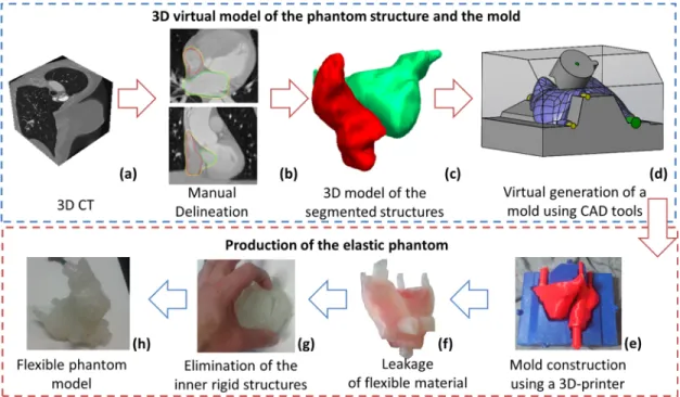
An overview of the proposed technique is presented in Figure 1. The patient-specific atrial model is constructed from a 3D CT of the patient (Figure 1a), by manual delineation of the left and right atria (LA, RA) and atrial wall (Figure 1b). Multiple 2D slices are manually segmented and then 3D reconstructed (Figure 1c). These 3D surfaces are required to generate a mold (as a negative of the target shapes) using a computer-aided design (CAD) software package (Figure 1d) and finally Figure 1 - Overview of the proposed method to construct patient-specific atrial phantom models.5
physically constructed using a 3D-printer (Figure 1e). The final model is composed by inner structures (red molds in Figure 1e), which represents the hollow cavities of the atrial bodies, and an external mold (blue mold in Figure 1e), with the external shape of the target anatomy. The flexible phantom is created through the pouring of a flexible material inside the mold (Figure 1f), followed by the elimination of the inner rigid structures (red parts, Figure 1g). Each of these steps are described in detail in the following sections. Furthermore, a step-by-step description of the mold construction is presented in Multimedia File I.
2.1. Data acquisition
The 3D CT of the anatomy was acquired with a Sensation 64 (Siemens Medical Solutions, Erlangen, Germany). The acquisition was performed with 64 rows, rotation time 0.36 ms, gantry angle of ±30 degrees. One hundred and twenty milliliter (ml) of iodinated contrast agent (Omnnipaque 350; GE Healthcare, Waukesha, WI) was injected at 5 ml/s. A matrix size of 512 x 512 x 96 with an isotropic voxel spacing of 0.4 mm and a slice thickness of 1 mm were used. The dataset was reconstructed at the ventricular end-diastole phase, with a convolution kernel B20f. The patient was enrolled in this study with indications for left atrial pathology, but with normal anatomy. Because of the retrospective nature of this study, no written informed consent was obtained from the patient. 2.2. Manual delineation The manual delineation was initially performed for the atrial cavities, followed by the atrial outer wall. No pre-processing stage was used, using directly the real information of the image. All delineations were performed by one experienced observer using the Medical Imaging Interactive Toolkit Software (MITK, 21) and its specific interactive segmentation menu. Specifically, a few 2D slices were manually segmented and then used as anchors points to reconstruct the final 3D surface. The reconstructed surface was assessed and extra corrections were performed if needed.
6
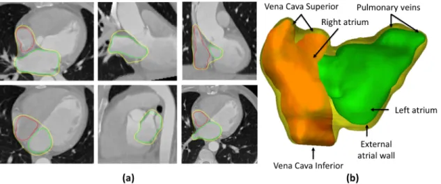
The LA and RA contours rely on the atrial body region, with both left and right atrial appendage being excluded (Figure 2). Moreover, only the proximal part of the pulmonary veins (PV) and vena cava (VC) were included. The mitral valve (MV) and tricuspid valve (TV) regions were identified by a plane. This plane was used to separate the target atrial region from the ventricular cavities. Multiple access points were defined for each atrium, namely: two for the PV, two for the VC (i.e. inferior and superior) and one for each ventricle. The size and orientation of each access point was defined with a specific contouring label. Since the current phantom model is intended to be used for planning/training multiple surgeries, realistic access points (i.e. similar to the real input and output orifices of the human atria) are required.
The external atrial wall was defined using the aforementioned LA and RA regions as references. Indeed, it was initially defined as a dilated version of the LA and RA with a constant thickness (approximately 3 mm). Then, multiple refinements were manually performed in order to guarantee maximum adaptation between the contour and the anatomy. It should be noted that intermediate atrial regions (i.e. inter-atrial septal wall) were merged. Moreover, free wall regions (e.g., mitral valve and tricuspid valve regions) were not refined and the constant thickness was kept. Figure 2 - Manual delineation strategy. a) Multiple 2D slices; and b) 3D representation of the atrial shape. Yellow – External atrial wall, Green – Left Atrium, Red – Right Atrium.
7
2.3. Virtual modeling of the phantom mold
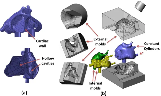
In order to manufacture the segmented anatomy, a cast-mold strategy was used. The entire design was performed on a CAD software package (SolidWorks, Dassault Systèmes S.A, Vélizy-Villacoublay, France) using multiple solids of the obtained segmentations (i.e. LA, RA and cardiac wall). The abovementioned solids were generated using GeoMagic (3D Systems, South Carolina). Note that, as output, a compact representation of each contour was obtained (i.e. the contour and its inner region are a unique solid without hollow regions). Specifically, the patient-specific mold was designed through a two-steps strategy, namely: 1) generation of the cardiac wall solid (see Figure 3a), through the intersection between the external atrial wall solid and the negative of both LA and RA solids. It should be noticed that the atrial wall solid is a compact component that includes both LA and RA solids and its outer surface Figure 3 - Technique used to create the phantom mold. (a) Three different solids (LA, RA and external atrial wall) are combined. (b) Using the combined solid, internal and external molds representing the negative of their shape were designed.
8
shape is the external atrial anatomy manually delineated in stage 2.2. As such, the intersection between the different components results in a new solid with hollow cavities (see Figure 3a), that represents the desired phantom anatomy;
2) design of the target mold as the negative of the cardiac wall solid generated in step (1). Due to the complexity of the atrial anatomy, three external (gray molds in Figure 3b) and two internal models (yellow and green mold in Figure 3b) are required. The external molds are the negative of the atrial wall, and the internal molds are the LA and RA solids themselves (see Figure 3b). Multiple external molds are needed to allow correct positioning of the internal parts, reduce manufacturing costs and consequently allow multiple usages of the same mold. As a result, after final mold construction through the combination of the different external and internal parts, a compact structure with a small cavity (i.e. empty space) was obtained. A schematic (with dimensions) of the phantom wall is presented in Multimedia File II.
Regarding the different access points (i.e. PV, VC, MV and TV), these were designed and constructed as constant cylinders with specific diameter and thickness (Figure 3b and dimensions in Multimedia File II). The cylinder orientation and positions were defined based on the user labeling done in section 2.2. Moreover, these cylinders are detachable in order to allow the pouring of material through multiple mold orifices, while guaranteeing the correct position of the inner molds relatively to the external mold. As a final remark, the authors would like to emphasize that these ‘adapted’ orifices can be used to develop a dynamic phantom by connecting hydraulic tubes to these cylinders, and therefore simulating the blood circulation into de atria (see one schematic of the dynamic phantom model in Appendix A). 2.4. Construction of the phantom mold using a 3D-printer The designed molds were converted into G-code format using the Cura software (Ultimaker, Geldermalsen, Netherlands) and 3D-printed using an Ultimaker II (Ultimaker, Netherlands).
9
Polylactic acid (PLA) was used (filament of 2.85 mm, Ultimaker, Geldermalsen, Netherlands). The following parameters were applied during the 3D-printing: speed of 60%, nozzle temperature of 225 °C, build-plate temperature of 60 °C, material flow at 100% and fan speed at 50%. An in-plane resolution (X-Y) of 0.25 mm with a layer height of 0.06 mm (resolution in Z) was used.
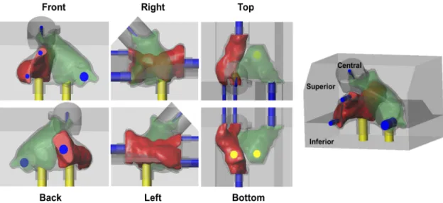
The printed mold is assembled as illustrated in Figure 4. We start by connecting the multiple cylinders (yellow for the ventricle region, and blue for the PV and VC) with the inner mold of the RA (green structure) and LA (red structure). Then, the obtained component (atria plus cylinders) is positioned on the inferior part of the external mold (see gray mold in Figure 4). The yellow and blue cylinders provide support and guarantee correct positioning of the inner molds. Finally, the mold is closed with the superior and central part of the external mold. As above mentioned, in order to pour the flexible material, each cylinder is detached (one at a time) and used as access point.
2.5. Flexible Materials
Two different materials were used to produce the flexible phantom, namely: silicone and polyvinyl alcohol cryogel (PVA - C, Figure 5). Figure 4 – Illustration of the assembled 3D printed-molds. Red and green are the inner molds of the right atrium and left atrium, respectively. Blue and yellow cylinders are the support structures to the pulmonary veins/vena cava and ventricles, respectively. The external mold (gray mold) is composed of three independent components, i.e. the inferior, superior and central.
10
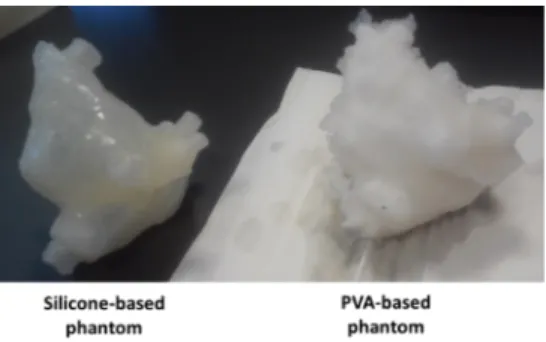
The silicone used is an additive HB FLEX 5513 A+B transparent (HBQuimica, Porto, Portugal). This material presents a Young’s modulus of approximately 720 kPa, linear contraction <0.05% and stretching until breaking of 450 %. The flexible material was prepared by mixing 75 g of both part A and B. Then, the material was poured into the mold. After 24 hours, the external molds were removed. Regarding the internal molds, one small incision was done to remove them, followed by the addition of silicone on the small incision region to close it. The PVA relies on Mowiol 10-98 (Kuraray Europe GmbH, Hattersheim am Maim, Germany) with a molecular weight of 61,000 𝑢, 98-98.8 mol% hydrolysis, ∼14000 polymerization, 1.1-1.9% of impurities, viscosity of 9-11mPa.s, 4% in H20 (20°C) and ester number of 15-25. Initially, the PVA powder was milled and mixed with water (temperature 80°C, during 2 hours), creating a viscous solution. This solution was subsequently poured into the mold. Then, two thaw-freeze cycles were performed, resulting in a compact and flexible wall with a Young’s Modulus of near 110 kPa and Poisson’s ratio of 0.45 22,23. Each cycle consisted of 12-h freezing period in a freezer at -20°C, followed by a 24h thawing period. At the end of the freezing stage, the freezer was turned off and the temperature slowly increased until the environment temperature. Finally, after 3-days, the external mold was removed and two incisions were mad to remove the internal molds. The viscous material was used to cover the incision site, and a third freeze/thaw cycle (12 hours freezing and 24 thawing) was performed. Figure 5 - Final silicone-based and PVA-C-based phantoms.
11
3. Experiments
Two independent experiments were performed to validate the proposed phantom model, namely: (i) evaluation of the accuracy of the proposed phantom production technique and (ii) qualitative and quantitative assessment of the resulting ultrasound image of each phantom model. 3.1. Accuracy of the proposed production technique After phantom production, we assessed the accuracy of the proposed production technique, through the comparison between the resulting phantom models and the original virtual design. In this sense, a high-resolution CT image was acquired for each constructed model (i.e. PVA-C and silicone), using a Somatom Force CT (Siemens Medical Solutions, Erlangen, Germany). A total of 2 x 192 rows, with a collimator width of 0.6 mm, a rotation time of 250 ms and a convolution kernel Ur73u was used. Furthermore, a matrix size of 512 x 512 x 437 with an isotropic pixel spacing of 0.35 mm and a slice thickness of 0.3 mm was used.
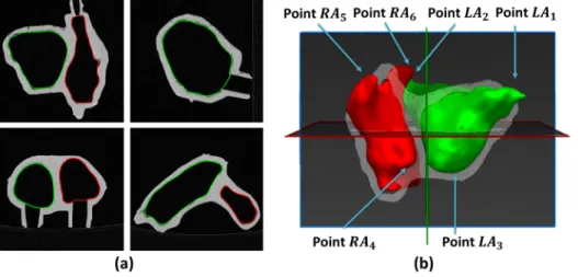
The obtained images were manually delineated using MITK. A threshold-based strategy followed by manual corrections was applied to generate the 3D surfaces of the LA and RA bodies and cardiac wall (Figure 6). In order to compare the post-production meshes with the
pre-
Figure 6 - (a) CT image with manual delineated contours. (b) 3D surface of the left and right atrium and representation of the manual landmarks required to perform the surface alignment. Green – Left atrium, Red – Right atrium.
12
production one, a surface-to-surface alignment using the iterative closest point algorithm (ICP, 24) was applied. Specifically, a set of landmarks were manually selected in each model (see Figure 6b), allowing to initially align both models with a similar orientation and position, which was subsequently refined using a rigid ICP strategy. An overview of the selected landmarks is presented in Figure 6b, in which we can observe that the model’s extremities were used to obtain a robust initialization. The initial transformation was computed through a least square solution between the reference (pre-production model) and target (post-production model) landmarks. The optimal rigid transformation (initialization plus ICP) was finally applied to each surface (i.e. LA, RA and cardiac wall), consequently aligning the pre- and post-production models. The differences between pre- and post-production surfaces (i.e. LA, RA and cardiac wall) were assessed through three metrics, namely point-to-surface (P2S) distance, Dice and 95th percentile of the Hausdorff distance. The volume of each chamber was also computed. Furthermore, we evaluated the accuracy of the method for thin walls (in this case, the inter-atrial septal wall). As such, a small region of interest (ROI) was created around the thin wall region. This ROI was defined as the largest connected region with a thickness lower than 5 mm. The abovementioned threshold (i.e. 5 mm) was selected based on the expected thickness of the thinner region, as previously described in literature 25.
3.2. Qualitative and quantitative evaluation of the phantom model in ultrasound imaging Both phantom models (i.e. silicone or PVA-C) were submerged in a large water tank (water at room temperature and tank dimension of 45.5x35x25 cm3) and the resulting ultrasound images were evaluated. The acquisition was performed with a transesophageal echocardiography (TEE) ultrasound probe (Vivid E9 Breakthrough 2012, General Electrics, Connecticut, USA) connected to a 4D-ultrasound system (Vivid E9, General Electrics, Connecticut, USA). The maximum image depth
13
was 18 mm and the image resolution was 0.07x0.07x1 mm3. The frequency of the transducer was set to 4 MHz. The differences in terms of image appearance were visually evaluated by one observer. Next, in order to compare the resulting ultrasound images of each phantom model with the ideal reference, we applied a strategy similar to section 3.1. In detail, we start by manually segmenting the LA and RA in each US image (for each model), identifying subsequently multiple landmarks to initialize the alignment strategy (see Figure 6b). A final refinement through a rigid ICP is applied to improve the alignment of both US and reference surfaces. Finally, the difference between each surface is quantitatively assessed using the P2S, Dice and 95th of the Hausdorff distance. Moreover, the volume of each surface extracted from the US is computed and compared with the ideal value.
4. Results
Table 1 shows the shape differences between the final post-production silicone-based and PVA-C-based phantom models (through a CT acquisition) when compared with the ideal model. The errors spatial distribution is presented in Figure 7, showing the high accuracy of the production technique for the real atrial body. A superior performance was found for the silicone-based
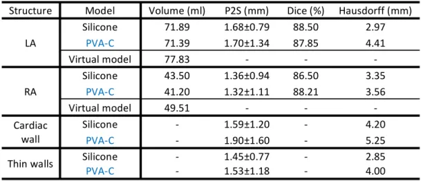
Table 1 - Assessment of the proposed production technique in terms of volume, point-to-surface error (P2S, mm), Dice (%) and 95th percentile of the Hausdorff distance (mm). The study is performed independently for the left atrium (LA), right atrium (RA), cardiac wall and thin walls.
Structure Model Volume (ml) P2S (mm) Dice (%) Hausdorff (mm) LA Silicone 71.89 1.68±0.79 88.50 2.97 PVA-C 71.39 1.70±1.34 87.85 4.41 Virtual model 77.83 - - - RA Silicone 43.50 1.36±0.94 86.50 3.35 PVA-C 41.20 1.32±1.11 88.21 3.56 Virtual model 49.51 - - - Cardiac wall Silicone - 1.59±1.20 - 4.20 PVA-C - 1.90±1.60 - 5.25 Thin walls Silicone - 1.45±0.77 - 2.85 PVA-C - 1.53±1.18 - 4.00
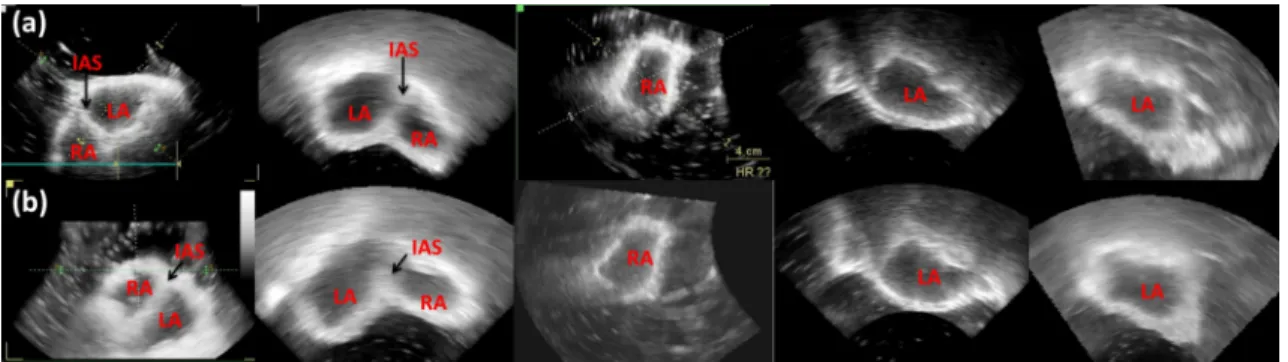
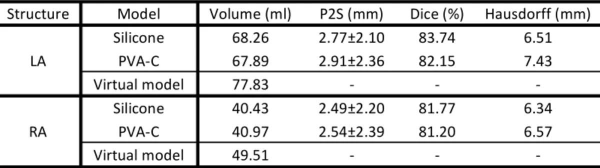
14 phantom. Moreover, Figure 8 shows the errors’ spatial distribution for the thin-wall, i.e. the inter-atrial septal wall, with both models showing high accuracy with a mean error around 1.5 mm and a maximum error of 2.8 mm. Figure 9 presents the ultrasound image appearance of each phantom model. Both chambers (LA, RA) and inter-atrial wall are easily visible. Furthermore, the final 3D shape observed in US was visually compared with the ideal model (Figure 10), showing a high similarity. Table 2 quantitatively compare (i.e. P2S, Dice, 95th percentile of Hausdorff and volume) the data extracted from the resulting US image and the ideal model, showing a moderate accuracy of the proposed method.
Figure 7 - Accuracy of the proposed production technique. (a) Left atrium, (b) right atrium, (c) cardiac wall. First row represents the silicone-based phantom, with the second row being the PVA-C-based phantom.
Figure 8 - Accuracy of the proposed production technique for thin walls. (a) Silicone-based phantom and (b) PVA-C-based phantom.
15
5. Discussion
In the current study, we present and assess the accuracy of a phantom production technique. The proposed strategy generates realistic and patient-specific models using as a reference a high-resolution medical acquisition based on CT. Besides the accurate representation of the atrial anatomy (i.e. LA and RA bodies), a correct representation of the inter-atrial wall was also pursued, improving the realism of the proposed atrial model. Indeed, particular attention was given to the design of the inter-atrial wall, consequently showing the particular interest of this phantom for simulation of atrial wall interventions, specifically: transseptal puncture26 and atrial septal defect closure27. To the author’s best knowledge, no patient-specific phantom model with correct representation of the mid atrial wall was previously presented, being a clear novelty of this work. Figure 9 - Resulting ultrasound image for (a) silicone-based and (b) PVA-C-based phantom. LA- Left atrium, RA – Right Atrium, IAS – Inter-atrial septal wall. Figure 10 - 3D visualization of the proposed phantom model in 3D US images. (a) Ideal model, b) Silicone-based and (c) PVA-C-based phantom model.
16
Regarding the phantom construction, it relies on four main stages: 1) accurate anatomical model generation using pre-procedural image acquisition, 2) virtual and 3) physical construction of the phantom mold and 4) pouring of the flexible and ultrasound-compatible material inside the mold. The first stage is applied to obtain an accurate representation of the patient anatomical details with a particular interest in the design of the atrial boundaries at the inter-atrial septum region, improving the accuracy of the phantom model at this region. Previous works have used a similar approach to generate the phantom model for catheter ablation simulation 19,20,28. Nevertheless, they failed to correctly generate the entire inter-septal wall 19,20. Furthermore, in order to allow the future expansion of the current model for a dynamic version similar to the suggested in Appendix A, the current phantom shape was segmented at the ventricular end-diastole (i.e. minimal atrial volume along the cardiac cycle). In this sense, by connecting a water pump with our flexible phantom, the beating of both atria can be simulated. In detail, the water pump continuously eject water inside the model, increasing the pressure inside the cavities and increasing their volume (simulating the ventricular end-systolic phase). Then, an interrupter (through a valve) can be posteriorly applied to stop the water flow, consequently reducing the pressure and reducing the atrial volume until the initial stage (i.e. end-diastolic phase).
Secondly (i.e. stage 2), the atrial and wall surfaces are exported into a CAD tool, virtually generating a mold that represents the target anatomy. This stage is also crucial to include multiple
Table 2 – Comparison of the atrial surfaces extracted from the ultrasound imaging and the ideal models. The comparison was performed in terms of point-to-surface error (P2S, mm), Dice (%) and 95th percentile of the Hausdorff distance (mm).
Structure Model Volume (ml) P2S (mm) Dice (%) Hausdorff (mm) LA Silicone 68.26 2.77±2.10 83.74 6.51 PVA-C 67.89 2.91±2.36 82.15 7.43 Virtual model 77.83 - - - RA Silicone 40.43 2.49±2.20 81.77 6.34 PVA-C 40.97 2.54±2.39 81.20 6.57 Virtual model 49.51 - - -
17
entry points (mimicking the circulatory system) on the target anatomy. Nevertheless, due to software (CAD) limitations with extreme irregular shapes, smoothed atrial surfaces were used (obtained through MITK), decimating the detailed mesh and making it suitable for the CAD software. Although this smoothing process will slightly modify the patient anatomy, it only represents a mean error of approximately 0.3 mm. Note that this error is lower than the CT voxel size (0.4 mm), which ultimately discretize the patient anatomy, or even the errors caused by the remaining stages of the production technique. During the remaining phantom construction stages (stage 3 and 4), rigid and outer molds are constructed using the recent 3D-printer technology (stage 3) and the atrial anatomy generated by leaking flexible material inside the mold (stage 4). Although such strategy allows a fast and accurate generation of complex anatomies, in particular of the inter-atrial walls (which are the focus of the current work), the usage of rigid inner molds hampers the inclusion of the atrial appendages and the pulmonary veins. Please note that, although 3D-printing could be directly applied to generate a flexible atrial phantom model (instead of a mold approach), allowing the inclusion of atrial appendages and pulmonary veins in the phantom model, ultrasound compatible 3D printing materials are not available hampering its application for simulation of the real intervention through ultrasound image 28, not following therefore the aims of the current study. Moreover, the proposed phantom construction through rigid inner molds is a sub-optimal approach, due to the latter incision of the final phantom model (required to remove the inner molds). Indeed, in order to improve the extraction stage, a 3D printing material with a dissolvable support solution or even a highly flexible inner mold (which could be extracted by the virtually generated entry points) could be interesting solutions, preventing the incision stage. Nevertheless, further studies to prove the real advantages of such techniques still missing.
In order to evaluate the accuracy of the described phantom production technique, we start by comparing a post-production CT acquisition of each model with the ideal reference. Both models
18 showed high accuracy (P2S always lower than 2 mm), being the errors found explained by several intrinsic limitations of the proposed technique, such as: material tolerance during 3D printing of the mold, flexible material retraction after cooling; reagent addition process; small errors linked to the delineation and errors caused by sub-optimal surface alignment through ICP. When comparing both models, a superior performance was found for the silicone-based phantom, which is clearly supported by the different metrics assessed in Table 1 and through the errors’ spatial map (Figure 7). Indeed, the low performance found for the PVA-C-based phantom is related with the low viscosity of the material, which hampers the material pouring and the incision closing stage. Furthermore, and contrary to the silicone-based phantom, the PVA-C-one required storage in a controlled environment (i.e. water tank with water at a specific temperature) and an inherent small shrinking of the material along the time was observed, which again can explain the lower accuracy of this model.
Due to the particular interest on the inter-atrial wall, we also assessed the technique accuracy at this specific region (Figure 8). Again, a mean error of approximately 1.5 mm was obtained for the silicone and PVA-C-based phantom at the selected ROI, corroborating their accuracy and applicability for the simulation/training of the aforementioned interventions. Interestingly, it is possible to observe that the lower errors (Figure 8) were found at the central position of the selected region, being the highest errors detected on the limits of the ROI. This result is explained by the anatomy of the inter-atrial wall, being thin and straight at the central part and presenting a more complex shape in the peripheries 25,29. In this sense, the proposed phantom construction technique was able to accurately generate the straight inter-atrial wall, presenting a sub-optimal performance on the remaining regions. Nevertheless, the authors would like to emphasize that the majority of the inter-atrial interventions focus on the straight inter-atrial wall (e.g. transseptal puncture26).
19
In order to assess the adequacy of the proposed phantom model for atrial interventions, we also assessed the resulting model appearance on a traditional intra-procedural image modality, namely ultrasound. Indeed, the acquired ultrasound images (Figure 9) proved that the different cardiac chambers (i.e. LA and RA) can be easily observed and identified in both phantom models (i.e. silicone-based and PVA-C-based). Similar to the expected and observed in normal clinical practice, a double chamber view was easily obtained for both models. A 3D analysis of the obtained ultrasound model (Figure 10) showed a high similarity when compared with the pre-production one. Moreover, a clear definition/identification of the inter-atrial septal wall was also achieved, reinforcing the appropriateness of the proposed phantom model for inter-atrial wall interventions. Although gelatin-based phantom models have been widely described for different scenarios 30,31, its application for this specific model was not possible due to its mechanical properties (high viscoelasticity and low stiffness).
Similar to the post-processing evaluation experiment (section 3.1), a comparison between the data extracted from the US and the ideal model was also performed. Globally, the results (Table 2) confirmed a moderate accuracy of the different phantom models, presenting errors lower than 3 mm for both chambers. A slightly superior performance of the silicone-based model was found when compared with the PVA-C model, which is explained by the more detailed walls observed (not so smooth as observed in PVA-C models, Figure 9) and also its superior accuracy throughout the phantom construction stage. Although an inferior performance was obtained in this experiment (Table 2) when compared with experiment 1 (CT acquisition versus ideal model, Table 1), it can be easily explained by the difficulties to visualize the boundary positions (instead of smooth boundaries as typically found in the US), image artifacts caused by the water tank walls used throughout the acquisition, difficulties to detect limits of the generated orifices and to distinguish these region from the outer environment, and the low field of view of the TEE probe (which hamper the identification
20 of the phantom’s extreme positions and also superimposed regions with multiple interfaces) 32-34. Additionally and as discussed in other studies 32,35, manual segmentation of US image is more prone to errors and harder to be performed than in CT imaging, justifying again the higher errors found in Table 2. In order to increase the realism of the current ultrasound image, graphite particles or glycerin should be combined with the flexible material, as suggested in previous studies 14. Such particles will generate speckle noise in the resulting ultrasound image, making the cardiac wall heterogeneous (i.e. multiple intensity values in the ultrasound image) and thus obtaining more realistic, non-saturated walls. Furthermore, although PVA-C is typically described as one of the most realistic materials for ultrasound-based phantom model construction 36, superior performance was not visually found in this study. Thus, further analysis will be required to assess the real performance of each material. Regarding the mechanical properties, both materials presented a Young modulus higher (720 kPa for the silicone and 110 kPa for the PVA-C) than the expected for the real tissue. Note that previous studies focused on the estimation of the mechanical properties of the atrial region, showing that the elastic modulus varies with the specific atrial location and the specific patient anatomy. Indeed, a Young modulus between 20–70 kPa is usually reported for the entire atrial wall 37,38. Specifically for the thin wall region, a value around of 30 kPa is expected 37. In this sense, the developed phantom models are stiffer than in reality and assume a homogeneous elasticity throughout the entire model, consequently presenting a sub-optimal performance to mimic the real deformations of the atrial walls. In other words, when puncturing the atrial wall, a higher force (when compared with the real situation) would need to be applied on the needle to create an access route between the two cavities. Nevertheless, similar limitations can be found for previous phantom
21
models 16,19,39,40, due to difficulties to correctly replicate the complex and heterogeneous structure of the cardiac muscle.
Overall, the current phantom models proved its added-value for simulation of inter-atrial interventions. They overcome the previously described rigid or ultrasound not compatible models, allowing the simulation of all procedural stages (i.e., planning using CT and guidance through ultrasound). Moreover, both phantoms (i.e., silicone and PVA-C) were designed to allow its simple adaptation for a dynamic setup (as presented in Appendix A), making the procedural simulation/training more realistic. It should be noticed that since a clear visualization of the both atrial chambers was obtained with CT and US images, the current dual-chamber model also showed potential for its application as a development or validation scenario of novel image fusion strategies. Inspired by a similar goal, Laing et al.28 presented a flexible phantom model for transseptal puncture simulation. The model also uses realistic atrial models extracted from a CT, showing a high production accuracy when comparing a post-production CT acquisition with the real model. A correct representation of the fossa ovalis (optimal location of the transseptal puncture) is ensured through a post-processing of the obtained atrial surfaces. Nevertheless, a detailed description of the phantom construction strategy is missing. Furthermore, correct modeling of the mid thin atrial walls (except the fossa ovalis region) is not described and not validated, constant outer atrial walls are used, method’s validation using intra-procedural data (i.e. ultrasound) is not presented, and model’s expansion for a dynamic version is not possible. Finally, their production technique is more time consuming than the current one, taking upward of 2 weeks 28 against the 3 days required by the proposed silicone-based phantom (1 week for the PVA-C model), making the current method more attractive for the normal clinical practice 28. Moreover, it should be noticed that the current construction time of the proposed technique can be notably reduced through the application of an
22
automatic segmentation strategy focused on both atrial models and its mid-walls, as described in our previous work 41.
As future work, an exhaustive study about the optimal phantom material will be performed, identifying the compound that correctly mimics the real atrial tissue (i.e. similar mechanical properties, similar acoustic properties, among others). Furthermore, we intend to construct the proposed dynamic phantom model and apply it for simulation of specific inter-atrial interventions. By applying it in a real scenario, we expect to receive a correct and realistic clinical feedback of the proposed model, ultimately validating the proposed phantom for accurate simulation of such interventions. Finally, we intend to apply it as an optimal validation scenario for a novel integrated interventional framework, based on an image-fusion strategy, to assist the physician throughout inter-atrial interventions 26.
6. Conclusions
The proposed production technique showed high accuracy for the generation of patient-specific atrial phantom models with flexible and realistic walls. The current method overcomes some limitations of the state-of-the-art models (i.e. the majority are rigid and not personalized to the patient anatomy), allowing its use for intervention planning and training. Phantom production with silicone proved to be more accurate due to its simple manipulation, high viscosity, and a simple construction technique. Both phantom models proved to be suitable for interventional planning and training based on ultrasound guidance, being both chambers and inter-atrial wall easily identified. Moreover, a realistic anatomy of the entire atrial region was obtained in these two cases. Overall, due to the simple manipulation and superior accuracy during model construction, the silicone-based phantom appears to be more feasible for the construction of complex anatomies such as the atrial region.
23
Acknowledgements
The authors would like to acknowledge Walter Coudyzer and Steven Dymarkowski (Department of Radiology, UZLeuven, Leuven, Belgium) for providing the CT acquisitions.
The authors acknowledge “Fundacão para a Ciência e a Tecnologia” (FCT), in Portugal, and the European Social Found, European Union, for funding support through the “Programa Operacional Capital Humano” (POCH) in the scope of the PhD grants SFRH/BD/95438/2013 (P. Morais) and SFRH/BD/93443/2013 (S. Queirós).
Authors gratefully acknowledge the funding of Projects NORTE-01-0145-FEDER-000013 and NORTE-01-0145-FEDER-000022, cofinanced by “Programa Operacional Regional do Norte” (NORTE2020), through “Fundo Europeu de Desenvolvimento Regional” (FEDER).
24
Appendix A – Dynamic Atrial Phantom Model
In the current appendix, we propose a setup to develop a dynamic version of the proposed phantom model. Inspired by the previous work from Cygan et al. 39, where a hydraulic setup was described to mimic the beating of the left ventricle, we suggest a hydraulic scheme to simulate the beating of both atria. Since the LA and RA volume curves are quasi-synchronous (i.e. increase their volume until the end of the T wave, and then reduce until the end of the ventricular diastole), a continuous water pump can be used to control the volume in each atrium. The pump continuously ejects water into the circuit (outflow in Figure A.1), which circulates through the phantom until a reservoir. Since a closed pump circuit is used, a connection between the inflow (see Figure A.1) of the pump and the reservoir is used. A solenoid valve is used to mimic the atrial valve function and it state is controlled by a virtual electrocardiogram (ECG). The ECG is defined through a graphic user interface, and multiple trigger functions are applied to open or close the circuit. An on/off digital controller (+5/0V) is used to modify the valve position. Specifically, 1) before the T-wave, the valve is closed. As such, the pump will eject water into the setup, increasing the pressure inside the phantom and consequently the atrial volume. 2) after the T-wave and until the end of the ventricular diastole, the valve is open. In this sense, there is not pressure (or volume) increase within the phantom model, and the water only circulates through the phantom until the reservoir. An overview of the setup can be found in Figure A.1. For this specific scheme, we selected a CardioFlow 5000 (Shelley Medical Imaging Technologies, Canada) pump, which includes an external controller with an ECG simulation function and multiple triggers embedded. Furthermore, a 3/4’’ solenoid valve (Emerson, United State of America) is used.25 Figure A.1 – Schematic of the dynamic phantom model. (A) – Hydraulic pump; (B) Computer station; (C) Adapter between tubes; (D) Phantom mock model; (E) Teflon membrane to allow catheter insertion for minimally invasive atrial interventions training; (F) – Solenoid valve; (G) – Water reservoir. (D-1) and (D-2) are different views of the connections near the phantom model (D). Note that P1 and P2 represent the same positions in both schemes. Furthermore, for each tube, the inner and
outer diameter is represented (as inner/outer). PV – Pulmonary veins; VC – Vena Cava;
26
References
1. Estevez ME, Lindgren KA, Bergethon PR. A novel three-dimensional tool for teaching human neuroanatomy. Anatomical sciences education. 2010;3(6):309-317. 2. Preece D, Williams SB, Lam R, Weller R. “Let's get physical”: advantages of a physical model over 3D computer models and textbooks in learning imaging anatomy. Anatomical sciences education. 2013;6(4):216-224. 3. Sugand K, Abrahams P, Khurana A. The anatomy of anatomy: a review for its modernization. Anatomical sciences education. 2010;3(2):83-93. 4. Rengier F, Mehndiratta A, von Tengg-Kobligk H, et al. 3D printing based on imaging data: review of medical applications. International journal of computer assisted radiology and surgery. 2010;5(4):335-341.5. Winder J, Bibb R. Medical rapid prototyping technologies: state of the art and current limitations for application in oral and maxillofacial surgery. Journal of oral and maxillofacial surgery. 2005;63(7):1006-1015.
6. Carton A-K, Bakic P, Ullberg C, Derand H, Maidment AD. Development of a physical 3D anthropomorphic breast phantom. Medical physics. 2011;38(2):891-896.
7. Sodian R, Weber S, Markert M, et al. Stereolithographic models for surgical planning in congenital heart surgery. The Annals of thoracic surgery. 2007;83(5):1854-1857.
8. Spottiswoode B, Van den Heever D, Chang Y, et al. Preoperative three-dimensional model creation of magnetic resonance brain images as a tool to assist neurosurgical planning. Stereotactic and functional neurosurgery. 2013;91(3):162-169.
9. Matsumoto JS, Morris JM, Foley TA, et al. Three-dimensional physical modeling: Applications and experience at mayo clinic. Radiographics. 2015;35(7):1989-2006.
10. Tam MD, Laycock SD, Brown JR, Jakeways M. 3D printing of an aortic aneurysm to facilitate decision making and device selection for endovascular aneurysm repair in complex neck anatomy. Journal of Endovascular Therapy. 2013;20(6):863-867.
11. Jeevan M, Jebaraj R, Krishnakumar R. In-vitro Validation of Image Guided Surgery System with 3D Pre-Operative Visualization for Atrial Transseptal Puncture. Paper presented at: 18th International Conference on Information Visualisation (IV), 20142014. Link: http://ieeexplore.ieee.org/abstract/document/6902927/.
12. Huang X, Moore J, Guiraudon G, et al. Dynamic 2D ultrasound and 3D CT image registration of the beating heart. IEEE Transactions on. Medical Imaging, 2009;28(8):1179-1189. 13. Linte CA, Moore J, Wedlake C, Peters TM. Evaluation of model-enhanced
ultrasound-assisted interventional guidance in a cardiac phantom. IEEE Transactions on. Biomedical Engineering, 2010;57(9):2209-2218.
14. Heyde B, Cygan S, Choi HF, et al. Regional cardiac motion and strain estimation in three-dimensional echocardiography: A validation study in thick-walled univentricular phantoms. IEEE Transactions on. Ultrasonics, Ferroelectrics, and Frequency Control, 2012;59(4):668-682.
15. Vannelli C, Moore J, McLeod J, Ceh D, Peters T. Dynamic heart phantom with functional mitral and aortic valves. Paper presented at: SPIE Medical Imaging2015. Vol. 9415. 2015. Link: http://proceedings.spiedigitallibrary.org/proceeding.aspx?articleid=2210202.
16. Lesniak-Plewinska B, Cygan S, Kaluzynski K, et al. A dual-chamber, thick-walled cardiac phantom for use in cardiac motion and deformation imaging by ultrasound. Ultrasound in medicine & biology. 2010;36(7):1145-1156.
17. Olszewski R, Trawiński Z, Wójcik J, Nowicki A. Mathematical and ultrasonographic model of the left ventricle: In vitro studies. Archives of Acoustics. 2012;37(4):583-595.
27
18. Bourier F, Reents T, AMMAR-BUSCH S, et al. Sensor-Based Electromagnetic Navigation (Mediguide®): How Accurate Is It? A Phantom Model Study. Journal of cardiovascular electrophysiology. 2015;26(10):1140-1145.
19. Rettmann ME, Holmes III DR, Kwartowitz DM, et al. Quantitative modeling of the accuracy in registering preoperative patient-specific anatomic models into left atrial cardiac ablation procedures. Medical physics. 2014;41(2):021909.
20. Sun D, Rettmann ME, Packer D, Robb RA, Holmes DR. Simulated evaluation of an intraoperative surface modeling method for catheter ablation by a real phantom simulation experiment. Paper presented at: SPIE Medical Imaging2015. Proceedings of SPIE--the International Society for Optical Engineering. Vol. 9415. NIH Public Access, 2015. Link: https://www.ncbi.nlm.nih.gov/pmc/articles/PMC4576352/. 21. Wolf I, Vetter M, Wegner I, et al. The medical imaging interaction toolkit. Medical image analysis. 2005;9(6):594-604. 22. Fromageau J, Gennisson J-L, Schmitt C, Maurice RL, Mongrain R, Cloutier G. Estimation of polyvinyl alcohol cryogel mechanical properties with four ultrasound elastography methods and comparison with gold standard testings. IEEE transactions on ultrasonics, ferroelectrics, and frequency control. 2007;54(3):498-509. 23. Leśniak-Plewińska B, Cygan S, Żmigrodzki J, Kałużyński K. A new thick-walled conical model of the Left Ventricle. Paper presented at: Computational Vision and Medical Image Processing V: Proceedings of the 5th Eccomas Thematic Conference on Computational Vision and Medical Image Processing (VipIMAGE 2015, Tenerife, Spain, October 19-21, 2015)2015. Link: https://www.crcpress.com/Computational-Vision-and-Medical-Image-Processing-V-Proceedings-of-the/Tavares-Jorge/p/book/9781138029262
24. Besl, Paul J., and Neil D. McKay. "A method for registration of 3-D shapes." IEEE Transactions on pattern analysis and machine intelligence 14.2 (1992): 239-256.
25. Reig J, Mirapeix R, Jornet A, Petit M. Morphologic characteristics of the fossa ovalis as an anatomic basis for transseptal catheterization. Surgical and Radiologic Anatomy. 1997;19(5):279-282. 26. Morais P, Vilaça JL, Ector J, D'hooge J, Tavares JMR. Novel solutions applied in transseptal puncture: a systematic review. Journal of Medical Devices. 2017;11(1):010801. 27. Faletra FF, Perk G, Pandian NG, Nesser H-J, Kronzon I. Closure of Patent Foramen Ovalis and Atrial Septal Defect. In: Real-Time 3D Interventional Echocardiography. Springer; 2014:21-41.
28. Lainga J, Mooreb J, Bainbridgec D, Drangovaab M, Petersab T. Patient-Specific Atrium Models for Training and Pre-Procedure Surgical Planning. Paper presented at: SPIE Medical Imaging2017. Link: http://proceedings.spiedigitallibrary.org/proceeding.aspx?articleid= 2609152.
29. Anderson RH, Webb S, Brown NA. Clinical anatomy of the atrial septum with reference to its developmental components. Clinical Anatomy. 1999;12(5):362-374.
30. Gerstenmaier JF, McCarthy CJ, Brophy DP, Cantwell CP. Evaluation of the Particulate Concentration in a Gelatin-Based Phantom for Sonographically Guided Lesion Biopsy. Journal of Ultrasound in Medicine. 2013;32(8):1471-1475.
31. Richardson C, Bernard S, Dinh VA. A Cost-effective, Gelatin-Based Phantom Model for Learning Ultrasound-Guided Fine-Needle Aspiration Procedures of the Head and Neck. Journal of Ultrasound in Medicine. 2015;34(8):1479-1484.
32. Noble JA, Boukerroui D. Ultrasound image segmentation: a survey. IEEE Transactions on medical imaging. 2006;25(8):987-1010.
28
33. Housden RJ, Ma Y, Arujuna A, et al. Extended-field-of-view three-dimensional transesophageal echocardiography using image-based x-ray probe tracking. Ultrasound in medicine & biology. 2013;39(6):993-1005.
34. Haak A, Ren B, Mulder HW, et al. Improved segmentation of multiple cavities of the heart in wide-view 3-D transesophageal echocardiograms. Ultrasound in medicine & biology. 2015;41(7):1991-2000.
35. Huang Q, Zeng Z. A Review on Real-Time 3D Ultrasound Imaging Technology. BioMed research international. 2017;2017. 36. Ceh D, Peters TM, Chen EC. Acoustic characterization of polyvinyl chloride and self-healing silicone as phantom materials. Paper presented at: SPIE Medical Imaging2015. Liver 1595 (2015): 0-5. Link: http://proceedings.spiedigitallibrary.org/proceeding.aspx? articleid=2210201 37. Howard SA, Quallich SG, Benscoter MA, Holmgren BC, Rolfes CD, Iaizzo PA. Tissue Properties of the Fossa Ovalis as They Relate to Transseptal Punctures: A Translational Approach. Journal of interventional cardiology. 2015;28(1):98-108.
38. Hunter RJ, Liu Y, Lu Y, Wang W, Schilling RJ. Left atrial wall stress distribution and its relationship to electrophysiologic remodeling in persistent atrial fibrillation. Circulation: Arrhythmia and Electrophysiology. 2012;5(2):351-360.
39. Cygan S, Werys K, Błaszczyk Ł, Kubik T, Kałużyński K. Left ventricle phantom and experimental setup for MRI and echocardiography–Preliminary results of data acquisitions. Biocybernetics and Biomedical Engineering. 2014;34(1):19-24.
40. Stevanella M, Maffessanti F, Conti CA, et al. Mitral valve patient-specific finite element modeling from cardiac MRI: application to an annuloplasty procedure. Cardiovascular Engineering and Technology. 2011;2(2):66-76.
41. Morais P., Vilaça JL, Queirós S, et al. A competitive strategy for atrial and aortic tract segmentation based on deformable models. (in press) Medical Image Analysis. doi: 10.1016/j.media.2017.07.007. Link: http://www.sciencedirect.com/science/article/pii/ S1361841517301159