An encoderless high-performance synchronous
reluctance motor drive
Álvaro Oliveira, Diogo Cavaleiro, Ricardo Branco, Hazem Hadla, Sérgio Cruz Department of Electrical and Computer Engineering
University of Coimbra / Instituto de Telecomunicações Coimbra, Portugal
[email protected] Abstract—This paper presents an encoderless
high-performance synchronous reluctance motor drive for traction applications. The control system is based on the active flux concept and a hybrid rotor position estimation algorithm is used, being this algorithm based on the injection of high-frequency signals at low speeds and on the position of the active flux vector for medium and high-speeds. A smooth transition algorithm between the two rotor position estimation methods is provided. Moreover, in order to improve the efficiency of the overall drive system, a loss minimization algorithm is proposed in order to reduce the motor copper losses when operating in steady-state.
Experimental results obtained in the laboratory confirm the validity and adequacy of the proposed algorithms for the developed drive system.
Keywords—High-frequency signal injection; hybrid sensorless control; synchronous reluctance motor; loss minimization; active flux; cross-magnetic saturation.
I. INTRODUCTION
In recent years, the synchronous reluctance motor (SynRM) has received considerable attention by the research community due to the high-efficiency and torque density achieved with the new rotor designs. Hence, SynRM drives are now becoming a serious alternative to permanent magnet synchronous motor (PMSM) drives in those applications were a lower initial motor cost, ruggedness and a high-reliability are predominant factors in the choice of the drive system [1].
To achieve a high-torque density, SynRMs operate at a high-level of magnetic saturation, being the level of saturation dependent on the working conditions of the motor and on the control strategy adopted. In these circumstances, for a proper control of a SynRM drive, phenomena such as magnetic saturation, cross magnetic saturation and iron losses need to be taken into account in the modelling and control of such drive system.
Moreover, in applications like small electric vehicles, it is very important to reduce the overall cost of the traction drive system and increase its robustness. The encoder is thus a component that should be removed, by adopting encoderless control strategies for this type of motor, able to operate satisfactorily in the entire speed range, including zero speed.
Hence, this paper deals with the modelling, control and implementation of an encordeless SynRM drive for the traction system of a small electric vehicle. A hybrid rotor
position estimation algorithm is presented and a motor copper losses minimization algorithm is incorporated into the control system of the SynRM drive in order to maximize the efficiency of the drive, in order to extend the range of the target vehicle.
II. SYNRM MODELING A. SynRM Model
The implementation of a simulation model of the SynRM drive, using equations that describe the motor behavior as accurate as possible is a crucial step to accomplish the goal of achieving a precise and robust sensorless control system. The mathematic model for the simulation of a SynRM can be built using currents or fluxes as state variables [2-4]. As the model here developed includes cross magnetic saturation effects, the choice of currents as state variables would lead to the use of the inductance derivative values, leading to a more complex model. Hence, the magnetic fluxes were chosen as state variables in the SynRM model.
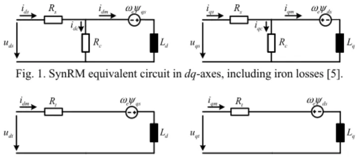
Fig. 1 shows the classic equivalent circuit of a SynRM, in a rotor reference frame, where uds,uqs,i ids, qs,dsand qs
represent the dq components, of the stator voltages, stator currents and stator flux linkages, respectively. and stand for the stator resistance and iron losses resistance, respectively, while Ld and Lq represent the stator windings
inductances along the d- and q-axis, respectively. The equivalent circuits adopted in this work, shown in Fig. 2, were derived from the ones shown in Fig. 1 by applying the Thévenin’s theorem. s R qs i qc i c R qm i q L e ds qs u s R ds i dc i c R dm i d L e qs ds u
Fig. 1. SynRM equivalent circuit in dq-axes, including iron losses [5].
q L t R qm i qt u e ds t R dm i d L dt u e qs
Fig. 2. Proposed SynRM equivalent circuits [4].
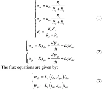
In these circuits, udt, uqt and Rt are given by (1).
The voltage and flux equations, in dq-axes, of the SynRM model are given by (2).
s
c dt ds c s c qt qs c s c s t c s R u u R R R u u R R R R R R R ì ï = ï + ï ï ï = í + ï ï ï = ï + ï î (1) ds dt t dm e qs qs qt t qm e ds d u R i dt d u R i dt (2)
The flux equations are given by:
, , ds d dm qm dm qs q dm qm qm L i i i L i i i (3)where L id
dm,iqm
and L iq
dm,iqm
emphasize thecross-coupling effects between the two axes.
After some mathematical manipulations, the equations that were implemented with the fluxes as state variables are given by ( , ) ( , ) t ds e d dm qm ds dt qs qt qs t e q dm qm R d L i i u dt u d R L i i dt (4)
These equations are complemented with the usual equations of motion, given by
e em L e e d p T T dt J d dt (5) where p is the number of pole-pairs, J is the combinedrotor-load inertia and is the electrical rotor speed. e The electromagnetic torque of the motor is given by
3 , , 2 em d dm qm q dm qm dm qm T p L i i L i i i i , (6) while the stator currents are calculated using the equations1 1 ds ds dc dm e qs dm c qs qs qc qm e ds qm c d i i i i R dt d i i i i R dt (7) B. SynRM Parameters
Due to the cross-saturation effects, in a SynRM both Ld
and Lq vary with id and iq.
There are different experimental methods to obtain the values of Ldand Lqas a function of currents, as described in
[6-8]. In this paper, these parameters were obtained using the methodology presented in [8]. The impact of cross-magnetic saturation in the values of and for the motorused in
the experimental tests is shown in Fig. 3. It is clear that for low values of current, this phenomenon cannot be neglected especially in the q-axis.
Fig. 3. Measured values of and .
In the simulation model, the variations of the two inductances were taken into account using 2D lookup tables.
The model of the motor also considers iron losses through the iron losses resistance which was obtained following the procedure presented in [4].
III. CONTROL SCHEME
There are many control strategies which have been proposed to achieve a high dynamic performance with SynRM drives. Among them we find strategies based on field oriented control (FOC) [1, 9], direct torque control (DTC) [10] and predictive torque control (PTC) [11]. The most common control strategy based on FOC is the maximum torque per ampere (MTPA). This strategy ensures the minimization of the motor copper losses for a given torque value but it fails when dealing with sensorless algorithms that require the fundamental component of the currents, for low motor torque values. Moreover, the MTPA strategy does not allow a direct control of the flux level in the SynRM, preventing a fast torque response [12].
To solve the above mentioned issues, as well as to have the ability to control the torque-producing flux in the SynRM, an active flux orientation control strategy was adopted [13]. As the active flux vector is always aligned with the d-axis, it can also be used to estimate the rotor position and speed with reliability. In addition, in order to achieve a high efficiency drive system, comparable to one using MTPA, a loss minimization algorithm was developed. This strategy minimizes the active flux reference in real-time for a given torque value. With these features it is possible to obtain a fast dynamic response and an accurate rotor position estimation in all operating conditions.
A. Proposed Vector Control System
By definition, the active flux a of an ac machine is the flux that multiplied by iqs gives the torque developed by the
motor [13]. The stator flux of a SynRM and the active flux are given by (8) and (9), respectively.
d ds q qs s L i jL i (8) q s a s L i . (9)
By entering (8) into (9) one obtains ( d q)ds
a L L i
. (10)
The electromagnetic torque developed by the SynRM is then calculated as d L Lq d L Lq c R
3 2
em a qs
T p i . (11)
Fig. 4 illustrates the steady-state vector diagram of a SynRM, with the active flux represented in red [14].
q d a s L iq s s i s s R i us e s j e ds a e qs
Fig. 4. Vector diagram of a SynRM in steady-state [14].
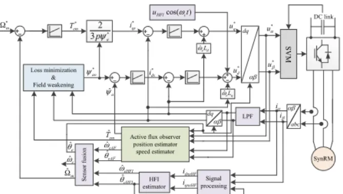
The sensorless vector control scheme proposed in this work is shown in Fig. 5.
SynRM * em T * m * qs i * ao * ds i dq u* * u DC link ˆa ˆ eAF dnsHF i i * d u ˆeAF ˆ eHFI ˆeHFI qnsHF i i ˆ m ˆ e ˆe ˆ em T dq abc Active flux observer
position estimator speed estimator * 2 3pa cos( ) HFI c u t LPF ˆe qL Signal processing HFI estimator * q u SynRM Se ns or f us ion ˆe dL Loss minimization & Field weakening SV M
Fig. 5. Block diagram of the implemented control system of the SynRM.
The distinctive features of this control system are the inclusion of a loss minimization algorithm which generates the optimum value of the active flux, as explained in a latter subsection of this paper, and the inclusion of a hybrid rotor position estimation algorithm, able to run from zero speed up to the rated speed of the motor. One algorithm for field weakening operation was also introduced in this control system.
The following subsections of the paper describe in detail each component of the control system.
B. Active Flux Observer
From previous considerations, it is clear that it is important to know the flux in the SynRM with accuracy. For this purpose, a hybrid flux observer was adopted, as illustrated in Fig. 6.
The flux estimation is based on the integration of the back-emf at medium-high speeds, as given by (12). At low speeds, this estimation is given by the current model as in (13), which uses the estimated inductances and measured currents to calculate i s . ( ) u s s s comp s u R i u dt
(12) ( ) e i j d ds q qs s L i jL i e (13) s i s R us dq dq q L ˆe ˆe ˆL T PLL i s ucomp us s ˆa ˆ e Fig. 6. Active flux observer with PLL [14].
The error between the two models is fed into the proportional-integral (PI) controller, which generates the compensation voltage ucomp (14) to account for estimation
errors, parameter variations during motor operation and other inherent errors of the drive system [14].
( )( ) ui i u ui i comp p s s K u K s (14)
It is important to highlight the fact that the fluxes given by (12)-(13) and the estimated active flux are expressed ˆa
in a stationary reference frame.
C. Loss Minimization
The goal of using loss minimization with the active flux strategy is to operate the SynRM with an optimal flux level, achieving a maximum efficiency over a wide speed range of operation [15].
The implemented strategy maximizes the efficiency during steady-state operation by reducing the electric power losses in the SynRM, given by
2 2 2 2 3 3 ( ) ( ) 2 2 e s ds qs c dc qc P R i i R i i . (15)
With reference to Fig. 1, the currents idqs and idqc can be
written as follows ; dqs c dqm dqs s dqm dqs dqc s c s c u R i u R i i i R R R R . (16)
Using (16) into (15) and after some manipulations, the following expression is obtained [16]:
2 2 2 3 3 2 2 qs s s c ds e s c s c d q u R R P R R R R L L . (17) By the analysis of (17), it can be concluded that the first term represents approximately the iron losses in the motor while the second one is mainly related to the motor copper losses. As the motor used in this work is a high-efficiency one with very low iron losses, the second term in (17) dominates the first in a wide speed range. Therefore, and for the sake of simplicity, the loss minimization algorithm only considers the minimization of the second term of (17).
Let us define M as 2 2 qs ds d q M L L . (18) Rewriting (6) in terms of flux components, the
3 1 1 2 em ds qs q d T p L L . (19)
Manipulating (19) in order to obtain as a function of qs ds
and replacing it on (18), the term M will be only in terms of . Then, solving ds M /ds 0, one obtains the
optimum value for that minimizes M [15]: ds
4 2 4 2 9 ( ) em dopt d d q T L p L L . (20)
Using dopt in (19) one obtains qopt. The optimum
active flux value to be used as the reference flux in the control system can finally be calculated by using dopt and
qopt
in (9).
D. Field Weakening
In certain applications like traction drives, a wide speed range is necessary. To achieve that, the motor needs to operate in the field weakening region [17]. To use the SynRM in this region, under the active flux orientation, the voltage and current limitations imposed by inverter must be taken into account. Neglecting the stator resistance of the SynRM, the voltage limit is respected by imposing a reference active flux according to the speed and the DC link voltage (UDC) given by:
2 2 * 2 3 DC a q qs q ds e U L i L i . (21)The motor phase current is limited by the quadrature current reference according to:
* 2 *
s max
qs ds
i i i , (22)
where is max is the amplitude of the motor rated current. The limitation of i bounds the current amplitude within qs
the inverter limit while the limitation of the active flux amplitude ensures that the steady-state motor voltage will remain within the limits of the inverter maximum voltage.
IV. SENSORLESS SYNRMDRIVE
The rotor speed and position estimation algorithms for motor drives can be broadly grouped into two categories: (i) methods based on the fundamental-excitation terms of the motor; (ii) methods that exploit the rotor anisotropies via high frequency injection (HFI) of signals [18, 19].
The methods that fall into the first category are usually the preferred ones as they do not interfere with the normal operation of the motor. These methods can be subdivided into four categories: (i) extended electromotive force (EMF) [20]; (ii) estimation through the flux [21]; (iii) Extended Kalman Filter (EKF); (iv) algebraic manipulation of SynRM equations in function of rotor angle [22]. Usually these methods cannot provide satisfactory performance at low speeds and standstill [18, 20, 23] because at reduced speeds the voltage applied to the motor is very small, being sensitive to noise, parameter variations, inverter dead-time, etc. The HFI methods, on the other hand, can provide good precision but have some drawbacks such as torque oscillation, acoustic
noise, harmonic propagation and extra dc voltage consumption [18, 23].
In order to achieve full torque controllability in the entire speed range, including zero speed, an hybrid estimator combining one method of each category can be used [14, 23]. In this paper, it is proposed a hybrid estimator with an enhanced algorithm for smooth transition between the two estimation algorithms. The method here reported combines an HFI algorithm for low speeds, including standstill, with an active flux based estimation algorithm for medium and high speeds.
A. High Frequency Injection
There are three different approaches how high frequency (HF) signals can be injected for rotor position estimation. The first is the injection of a rotational voltage vector in a stationary reference frame; the second one is the use of a rotational voltage vector in the estimated rotor reference frame, and the third method is the use of a pulsating voltage vector in the estimated rotor reference frame [24, 25]. Some studies have found that using a pulsating vector injection the estimator is more precise than using a rotational vector injection [26, 27], thus justifying the use of this type of injection in this paper. If a pulsating voltage vector is chosen, it is advantageous to inject the signal along the d-axis to avoid higher torque oscillations that could be introduced in the case of an injection along the q-axis.
In the developed drive system, a pulsating voltage vector is injected along the estimated d-axis, with an amplitude uh
and frequency (rad/s): h
cos( ) 0 dsh h h qsh u u t u . (23)
The error between the actual and the estimated rotor position is defined by
ˆ
err r r
. (24)All motor high-frequency impedances in the estimated rotor reference frame are function of the rotor position estimation error, being given by
ˆ ˆ ˆ 1 cos(2 ) 2 1 cos(2 ) , 2 1 sin(2 ) 2 r r r dh avg dqh err qh avg dqh err ch dqh err Z Z Z Z Z Z Z Z (25) where ˆ ˆ ˆ , , Z r r r dh qh ch
Z Z represent the dq components of the high frequency impedance of the SynRM in the estimated reference frame and the cross-coupled high frequency impedance, respectively. At high frequencies, hLRs,
meaning that the terms corresponding to the impedance in (25) can be approximated by dqh dq h avg avg h Z L Z L (26) where
; 2 r r dh qh r r dq d qh avg L L L L L L (27)
In (27), Ldqis the inductance saliency while Lavg
represents the mean position independent inductance.
The cross-coupling high-frequency impedance in the estimated rotor reference frame is proportional to sin(
err)as the SynRM has magnetic saliency given by Ld /Lq [28].The HF voltage injected along the d-axis will create a HF current in the estimated q-axis if the estimated rotor position mismatches the actual rotor position. This HF current component that contains information about the position error can be given by [28]:
ˆ
ˆ cos sin 2 cos
2 r h dq err r ch h qh r r h h r r h dh qh h dh h qh j L Z u i u t t Z Z j L j L (28) In order to eliminate the fundamental component of current, to extract the HF component, a signal processing procedure similar to the one described in [28] was adopted, as illustrated in Fig. 7.
s i idqˆr ˆr q i rˆsin( ) q h i t f(err) ˆeHFI ˆ eHFI dq err K sin(ht)Fig. 7. Block diagram of signal processing procedure for rotor position and speed estimation [28].
Most of the HFI schemes use more than one filter applied to the current [14, 18, 23, 24, 28]. In the proposed method, which was originally proposed in [28] for PMSMs, only one LPF is used to filter the current to avoid the lag introduced by over-filtering.
Then (29) is obtained, which is a function proportional to the position estimation error [29].
( )
2
h dq
err r r err err err
h dh qh u L f K L L (29)
B. Position and Speed Estimators Using the Active Flux
As the active flux vector falls along the rotor d-axis, its phase angle is equal to the rotor position and it may be caclulated by [21] 1 ˆ ˆ tan ˆ a er a , (30)
where ˆa and ˆa are the estimated components of the active flux in a stationary reference frame. The angle thus obtained is applied to the PLL shown in Fig. 8, and the estimated position and rotor speed are obtained. This observer is a phase-locked loop (PLL), enhanced with the acceleration component obtained from the equation of motion of the SynRM to improve the response of the observer during speed transients. The observer gains used in the experimental tests were K150, K2 1500, K3 15.
The outputs of the PLL ˆeF, , are the angular position ˆeF
and the rotor electrical speed estimation through the active flux observer and B stands for the friction coefficient.
ˆa 1 ˆ tan ˆ a a ˆ em T ˆL T / p J B p ˆeF ˆ eF sin 3 K K2 K1
Fig. 8. PLL based speed, position and load observer [14].
The advantage of using a PLL over a PI is that the estimation is more robust to load variations and also the obtained speed signal has a lower ripple.
C. Estimator Changeover
The changeover between the two position estimation methods needs to be as smooth as possible otherwise it will affect the system stability [23]. Equation (31) defines the speed at which the transition starts, its duration in rpm and transition state, respectively.
450 rpm 40 rpm ˆ tra state m tra (31)
The function used to alleviate the transition is defined by (32) and the algorithm for the changeover is shown in Fig. 9 [29] where is the angle which is going to be used by the c
control system. ˆ ˆ ˆ 1 ˆ ˆ ˆ ˆ eHFI m tra state state
c eHFI eF tra m tra
eF m tra (32)
To attenuate the ominous effects of the HF injection signals, the amplitude of the injected voltage is initially 40 V (with a frequency of 1100 Hz) and then decreases as the motor speed starts to increase, according to the function [29]
40 h h h m K u K . (33)
The attenuation factor Kh was set to 600 in the
experimental tests documented in the following section.
Fig. 9. Block diagram for the two rotor position estimators transition.
ˆ ? tra m ˆ ? tra m ˆ c f m ˆ c aF ˆ c eHFI ˆ ? tra m ˆ ? tra m
V. EXPERIMENTAL RESULTS
The model of the encoderless SynRM drive was developed in Matlab/Simulink environment and implemented in a dSPACE 1103 controller board.
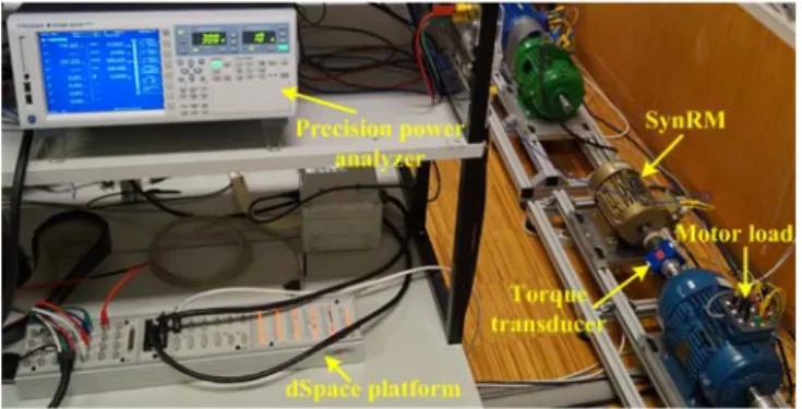
The SynRM used in experimental tests is a high efficiency (IE4) 4-pole KSB motor, whose main parameters are shown in Table 1. An induction motor of 7.5 kW fed by an inverter was mechanically coupled to the SynRM to act as a load. An encoder of 1024 ppr was used solely to evaluate the errors of the rotor position estimation algorithms. A sampling frequency of 18 kHz was used.
TABLE I. SYNRM PARAMETERS.
Rated power 3 kW Rated torque 19.1 N.m
Rated voltage 355 V Rated speed 1500 rpm
Rated current 7.9 A Rated efficiency 90.4 %
Rated frequency 50 Hz
An overview of the experimental setup can be seen in Fig. 10
Fig. 10. Experimental setup. A. Standstill Operation
Fig. 11 shows the encoderless operation of the SynRM drive at standstill, initially unloaded and then loaded with a load torque step of 95% of the rated motor torque introduced at t=0.5 s. The tracking of the initial rotor position was done via HFI.
As can be seen in Fig 11(a), after a short transient period, the motor is able to maintain zero speed proving that the developed control system is able to maintain motor torque controllability at standstill. The error of the estimated rotor position is very small in steady-state (Fig 11(c)). In transient conditions, there is some error in the rotor position estimation, although it is enough to affect the drive stability. The torque and current ripple is a consequence of the voltage HFI. This test and others, conducted at different load levels, show that this drive is capable of developing the motor rated torque at zero and low speeds, ensuring a fast acceleration needed in traction applications.
B. Speed Reversal
A speed reversal test from 1500 rpm to -1500 rpm was performed in order to evaluate the transition between the two rotor position estimation algorithms and also the transient performance of the drive system (Fig. 12). In the
Fig. 11. Standstill operation of the encoderless SynRM drive for a load torque step of 18 Nm introduced at t=0.5 s: (a) speed; (b) motor torque; (c)
rotor position; (d) current.
Fig. 12. Speed reversal test from 1500 rpm to -1500 rpm, at no load, with loss minimization: (a) rotor speed; (b) torque(c) rotor angle error; (d)
current.
initial part of the speed transition, the rotor position is estimated using the active flux algorithm, ensuring a low error for medium speeds.
It is visible that when the speed becomes low, the rotor angle error introduced by this algorithm starts to increase. When the rotor speed approaches -490 rpm (t=1 s), the HFI algorithm starts to take over and reduces the rotor angle error, ensuring the motor controllability. During the acceleration phase, the HFI algorithm starts losing importance in the estimation process at 450 rpm and the active flux algorithm regains its role. It is worth mentioning that the rotor angle error in steady-state approaches zero, thus demonstrating the effectiveness of the proposed estimation processes.
C. Speed Transition With Constant and Minimized a
Fig. 13 shows the obtained results for the system with and without loss minimization in a transition from 800 rpm
-40 -20 0 20 n (rp m ) 0 10 20 Tem (N m ) (a) -200 0 200 e (º ) (b) 0 0.5 1 1.5 2 2.5 3 -10 0 10 ia (A ) (d) Time (s) (c) nest nreal est real -1500 0 1500 n (r pm ) (a) n real n est -10 0 10 erro r (º ) (b) 0.6 0.65 0.7 a (W b) (c) 0 0.5 1 1.5 2 2.5 3 -10 0 10 ia (A ) (d) Time (s)
Fig. 13. Comparison between traditional active flux control system and active flux system with loss minimization in a speed transition from 800 rpm to 1500 rpm: (a) speed; (b) torque; (c) active flux; (d) copper losses.
to 1500 rpm with 52% of rated torque. From Fig. 13(a) it can be seen that the speed response is very similar in the two situations. From Fig. 13(b) it can be seen that with the minimization strategy the torque takes more 0.1 s to reach its maximum value, because the motor needs some time for the flux to reach its nominal value . However the decrease in a
drive performance is not significant. Fig. 13(c) shows the active flux in the motor. When the minimization algorithm is used, the active flux reference is lower, thus leading to a lower ids. When the reference speed is increased, the
machine needs to develop torque and the loss minimization algorithm sets the active flux in its rated value. As soon as the machine reaches the reference speed, the need for torque decreases to 10 Nm (to maintain the load) and the algorithm calculates the new active flux reference. This causes a drop in ids of 2.6 (A) having a big impact in the cooper losses of
the machine as can be seen in Fig. 13(d). With the minimization algorithm it was possible to decrease the losses from 200 W to 95 W having a decrease of 53% in cooper losses.
D. Constant Power Region Operation
Fig. 14 shows the obtained results for a speed step change from 1000 rpm to 1700 rpm and demonstrates the drive ability to run in the constant power region. As can be seen in Fig. 14(a) the estimated and actual speed signals are similar. In Fig. 14(b) the developed torque is presented where it can be observed that the motor can develop more than 50% of the rated torque in this field weakening zone, which proves the drive robustness. Fig. 14(c) shows the error of the estimated rotor position which is very small in steady state operation, being almost zero even above the rated speed. Fig. 14(d) shows the active flux reference where it can be seen that for speeds higher than the rated the field weakening algorithm adjusts the active flux reference to satisfy a specific condition of speed and load torque.
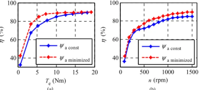
E. Efficiency Results
Fig. 15(a) shows the efficiency for the SynRM operation with a constant value for the reference active flux and using
Fig. 14. Transition from 1000 rpm to 1700 rpm, for a constant load torque of 10Nm: (a) speed; (b) torque; (c) rotor angle error; (d) active flux.
0 5 10 15 20 40 60 80 100 (% ) Te (Nm) a const a minimized 0 500 1000 1500 40 60 80 100 (% ) n (rpm) a const a minimized
Fig. 15. Efficiency of the SynRM drive with and without loss minimization: (a) efficiency vs torque; (b) efficiency vs speed.
the loss minimization algorithm. This test was made maintaining a constant speed of 1200 rpm while the load torque was varied between zero and the rated value. As can be seen, with a constant active flux the maximum efficiency is only achieved when the load torque is close to the rated value. On the other hand, using loss minimization it is possible to reach almost the maximum efficiency with smaller values of the load torque (above 7 Nm). Below this value of the load torque the efficiency drops because it is necessary to maintain a minimum value for the active flux in order to ensure the estimation of the rotor position.
Fig. 15(b) shows the variation on the SynRM efficiency versus speed, for the two conditions (using a constant and an optimized value for the active flux). This test was made with a constant load torque of 8 Nm. The efficiency difference between the two described situations is around 5% in the medium and high speed region.
VI. CONCLUSION
This paper presented a robust encoderless high-performance synchronous reluctance motor drive able to operate in a wide range of speeds, aimed for traction applications. A hybrid rotor position estimation algorithm using high-frequency injection signals and the position of the active flux vector allows this drive system to have full load torque controllability at zero and very low speeds, thus overcoming one of the main drawbacks of the most common
700 1500 n (r pm ) (a)
nest aconst nest aminimized
10 20 Te (N m ) (b) Tem aconst Tem aminimized 0.5 0.6 0.7 a (W b) (c) aconst aminimized 0 0.2 0.4 0.6 0.8 1 1.2 1.4 1.6 1.8 2 100 200 300 400 Plo sse s (W ) (d) Time (s)
Plosses aconst Plosses aminimized
1000 1500 n (r pm ) (a) nest nreal 0 10 20 Te (N m ) (b) 0 5 erro r (º ) (c) 0 0.2 0.4 0.6 0.8 1 1.2 1.4 1.6 1.8 0.5 0.6 0.7 a (W b) (d) Time (s)
sensorless control algorithms.
The tracking of the rotor initial position is done with accuracy using the HFI algorithm, ensuring a safe startup of the drive.
In view of the target application of the developed drive, a loss minimization strategy was developed in order to increase the efficiency of the motor in steady-state. The algorithm allows setting an optimal value for the active flux reference and, as a result, to minimize the motor copper losses when operating in steady-state conditions.
In view of the high degree of magnetic saturation found in SynRMs, an accurate characterization of the motor inductances, including the cross magnetic saturation effect, was fundamental to achieve a high performance control system.
ACKNOWLEDGMENT
The authors acknowledge the financial support of the Portuguese Foundation for Science and Technology (FCT) under project PEst-OE/EEI/LA0008/2013.
REFERENCES
[1] E. Daryabeigi, H. Abootorabi Zarchi, G. R. Arab Markadeh, J. Soltani, and F. Blaabjerg, "Online MTPA control approach for synchronous reluctance motor drives based on emotional controller," IEEE Transactions on Power Electronics, vol. 30, pp. 2157-2166, 2015.
[2] A. Kilthau and J. M. Pacas, "Appropriate models for the control of the synchronous reluctance machine," in 37th IAS Annual Meeting Industry Applications Conference, 2002, pp. 2289-2295.
[3] Q. Zengcai, T. Tuovinen, and M. Hinkkanen, "Inclusion of magnetic saturation in dynamic models of synchronous reluctance motors," in XXth International Conference on Electrical Machines (ICEM 2012), 2012, pp. 994-1000.
[4] R. Branco, "Modeling and simulation of synchronous reluctance motors," M.Sc thesis, University of Coimbra, January 2015.
[5] X. Longya, X. Xingyi, T. A. Lipo, and D. W. Novotny, "Vector control of a synchronous reluctance motor including saturation and iron loss," IEEE Transactions on Industry Applications, vol. 27, pp. 977-985, 1991.
[6] S. Yamamoto and T. Ara, "Determination of direct and quadrature axis inductances of synchronous reluctance motors with allowance for cross saturation," Electrical Engineering in Japan, vol. 123, pp. 911– 917, August 2003.
[7] S. Yamamoto, T. Ara, and K. Matsuse, "A method to calculate transient characteristics of synchronous reluctance motors considering iron loss and cross-magnetic saturation," IEEE Transactions on Industry Applications, vol. 43, Jan./Feb. 2007.
[8] S.-H. Hwang, J.-M. Kim, H. V. Khang, and J.-W. Ahn, "Parameter identification of a synchronous reluctance motor by using a synchronous PI current regulator at a standstill," Journal of Power Electronics, pp. 491-497, September 2010.
[9] S. Yamamoto, H. Hirahara, J. B. Adawey, T. Ara, and K. Matsuse, "Maximum efficiency drives of synchronous reluctance motors by a novel loss minimization controller with inductance estimator," IEEE Transactions on Industry Applications, vol. 49, pp. 2543-2551, 2013. [10] S. Bolognani, L. Peretti, and M. Zigliotto, "Online MTPA control
strategy for DTC synchronous reluctance motor drives," IEEE Transactions on Power Electronics, vol. 26, pp. 20-28, 2011. [11] R. Morales-Caporal and M. Pacas, "Encoderless predictive direct
torque control for synchronous reluctance machines at very low and zero speed," IEEE Transactions on Industrial Electronics, vol. 55, pp. 4408-4416, 2008.
[12] A. P. Gonçalves, S. M. A. Cruz, F. J. T. E. Ferreira, A. M. S. Mendes, and A. T. D. Almeida, "Synchronous reluctance motor drive for electric vehicles including cross-magnetic saturation," in IEEE Vehicle Power and Propulsion Conference (VPPC), 2014.
[13] I. Boldea, M. C. Paicu, and G. Andreescu, "Active flux concept for motion-sensorless unified AC drives," IEEE Transactions on Power Electronics, vol. 23, pp. 2612-2618, 2008.
[14] S. C. Agarlita, I. Boldea, and F. Blaabjerg, "High frequency injection assisted "active flux" based sensorless vector control of reluctance synchronous motors, with experiments from zero speed," in Energy Conversion Congress and Exposition (ECCE), 2011, pp. 2725-2732. [15] D. Cavaleiro, "Synchronous reluctance motor for the traction system
of electric vehicles," M.Sc. thesis, University of Coimbra, January, 2015.
[16] J. Habibi and S. Vaez-Zadeh, "Efficiency-optimizing direct torque control of permanent magnet synchronous machines," in Power Electronics Specialists Conference, 2005, pp. 759-764.
[17] G. Pellegrino, E. Armando, and P. Guglielmi, "Direct flux oriented control of IPM drives with variable DC link in the field-weakening region," IEEE Transactions on Industry Applications, vol. 45, pp. 1619-1627, 2009.
[18] S.-K. Sul, Control of electric machine drive systems: John Wiley & Sons, 2011.
[19] M. Pacas, "Sensorless drives in industrial applications," IEEE Industrial Electronics Magazine, vol. 5, pp. 16-23, 2011.
[20] S. Ichikawa, M. Tomita, S. Doki, and S. Okuma, "Sensorless control of synchronous reluctance motors based on extended EMF models considering magnetic saturation with online parameter identification," IEEE Transactions on Industry Applications, vol. 42, pp. 1264-1274, 2006.
[21] I. Boldea and S. C. Agarlita, "The active flux concept for motion-sensorless unified AC drives: A review," in International Aegean Conference on Electrical Machines and Power Electronics, 2011, pp. 1-16.
[22] Z. Yue, W. Chun, Z. Zhe, and Q. Wei, "A review on position/speed sensorless control for Permanent-Magnet Synchronous machine-based wind energy conversion systems," IEEE Journal of Emerging and Selected Topics in Power Electronics, vol. 1, pp. 203-216, 2013. [23] W. T. Villet, M. J. Kamper, P. Landsmann, and R. Kennel, "Hybrid
position sensorless vector control of a reluctance synchronous machine through the entire speed range," in 15th International Power Electronics and Motion Control Conference, 2012, pp. LS4b-1.1-1-LS4b-1.1-7.
[24] Z. Huang, L. You, and Z. Wang, "Sensorless initial rotor position identification for non-salient permanent magnet synchronous motors based on dynamic reluctance difference," IET Power Electronics vol. 7, pp. 2336-2346, 2014.
[25] M. C. Paicu, I. Boldea, G. D. Andreescu, and F. Blaabjerg, "Very low speed performance of active flux based sensorless control: interior permanent magnet synchronous motor vector control versus direct torque and flux control," IET Electric Power Applications, vol. 3, pp. 551-561, 2009.
[26] K. Hyunbae and R. D. Lorenz, "Carrier signal injection based sensorless control methods for IPM synchronous machine drives," in Conference Record of the 2004 IEEE Industry Applications Conference, 2004, pp. 977-984.
[27] D. Raca, P. Garcia, D. D. Reigosa, F. Briz, and R. D. Lorenz, "Carrier-signal selection for sensorless control of PM Synchronous machines at zero and very low speeds," IEEE Transactions on Industry Applications, vol. 46, pp. 167-178, 2010.
[28] Z. Hao, X. Xi, and L. Yongdong, "A simplified high frequency injection method for PMSM sensorless control," in 6th International IEEE Power Electronics and Motion Control Conference, 2009, pp. 401-405.
[29] Á. Oliveira, "Sensorless control of a synchronous reluctance motor," M.Sc. thesis, University of Coimbra, January 2015.
![Fig. 7. Block diagram of signal processing procedure for rotor position and speed estimation [28]](https://thumb-eu.123doks.com/thumbv2/123dok_br/15724704.1070862/5.892.558.770.83.205/block-diagram-signal-processing-procedure-rotor-position-estimation.webp)