Concentrating Solar Power Technologies using Molten
Salts for Storage and Production of Energy
Master Thesis
Franclim Rodrigues Cardozo Dissertation submitted for the degree ofMaster in Environmental Engineering – Management Field ___________________________________________________________
Jury President: António Manuel Antunes Fiúza
(University Professor of the Mining Engineering Department at the Faculty of Engineering, University of Porto - FEUP)
___________________________________________________________ Academic Coordinator: Luis Miguel Palma Madeira
(Associate Professor of the Chemical Engineering Department at the Faculty of Engineering, University of Porto - FEUP)
___________________________________________________________ Company Coordinator: Jose Luis Romeral Martínez
(Director of Energy Area at Fundació CTM Centre Tecnològic – CTM; Director of MCIA Center at Catalonia Polytechnic University - UPC)
Performed in
Fundació CTM Centre Tecnològic
Department of Environmental Engineering
Acknowledgements
The first words of this thesis are dedicated for the people who helped me in many ways for making this work. I would like, sincerely, to thanks to:
Prof. Luis Madeira from Portugal who gave me a crucial orientation during my stay in the company even being far away and helped me to get this internship abroad.
Dr. Luis Romeral from CTM for the opportunity given in developing my master thesis under a professional experience in his Area of Energy, more specifically, renewable energy and for the support provided during the internship.
Engª. Tamara Tolon for all the orientation and help provided during my stay in CTM and time spent in meetings regarding my work since the beginning till the end. It was a pleasure to work with such a good professional.
Eng. Jordi Macia for all the Matlab help and all the new features of this software that I’ve learned thanks to him and also his time spent.
Eng. Aleix Badia for his help in my integration in the city of Manresa and also specifically the help supplied in Matlab coding.
Eng. Marc Castellà for the Simulink help given during the last part of this work, namely developing the model, and also for the mornings and afternoons of work.
Eng. Joan Junyent for the relaxed and funny moments provided during those five months in the company and also for some tips to get information about molten salts properties.
Eng. Mario Heredero for the help provided in the electrical generation system of the thermo solar plant.
Engª. Isabel Rojo for the information provided about residual salt mining operations.
All my family and for their support provided during these five months even far away from them. Thank you dad, mom and brother, without you, it would be impossible to have such a good experience like I had and pass through everything like I did.
All my friends, specially Albino, Costa, Joel, Jorge, Nuno, Sophie, Roby and Pedro, who gave me an important support during this experience and never let me down along these years of friendship.
Abstract
The developed work approaches a connection between concentrating solar power (CSP) technologies and an innovative storage system with molten salts. An evaluation of salt mining is done in order to better understand if the residual salt of mines can be used as heat transfer fluid and storage media in CSP, due to the existence of those mines in Catalonia, Spain. It is stated that cooperation between the mining sector and CSP plants doesn’t exist and it could be a great idea for re-using these residual salts. A state of the art of CSP technologies is made and the main conclusions of previous works are presented, as also descriptions of energy storage technologies, heat transfer fluids (HTF) used and main design requirements and operation parameters for an optimization of energetic performance.
A model of a CSP plant based on central tower receiver (CTR) technology is implemented on Matlab© using molten salts as heat transfer fluid (HTF) and storage media, where the solar position and radiation are also developed and simulated. Once developed the model implemented in Matlab©, an analysis and control of the simulation results is done. The defined parameters, such as operation temperatures between 290 ºC and 565 ºC, and the solar thermal power reached by the tower receiver, exhibits a coherent behavior, having peak values between 12h00 and 14h00 along a day and different values between summer and winter seasons; so, the thermal power is higher along the summer and lower along the winter followed by the solar radiation. The effect of raising the mass of molten salt in each tank provokes different performances of the CSP plant, such as a higher autonomy between 2.6 and 3.6 hours depending on year season, winter and summer, respectively. This plant is defined for particular design and key operation requirements but the molten salt can be adaptable to different parameters/conditions of the plant, to different power demand or even the selected CSP technology.
Keywords: Concentrating Solar Power, renewable energy, thermal energy storage, design, analysis and control of CSP operation, molten salts.
Declaration
I declare, under honor commitment, that this work is original and all non-original contributions were properly referred with sources identifications.
Contents
Contents ... i
Abbreviations and symbols list ... iv
Abbreviations ... iv
Variables and Units used ... v
Greek letters ... vi
Glossary ... viii
Illustrations and Tables list ... xi
1. Introduction ... 1
1.1 Background and project presentation ... 1
1.2 Company Presentation ... 1
1.3 Work contribution ... 1
1.4 Organization of the Thesis ... 2
2. State of the art ... 3
2.1 Energy characterization of the mining sector ... 3
2.1.1 Mining sector in Catalonia, Spain ...4
2.2 Characterization of residual salts available in mines ... 6
2.3 CSP energy production technologies ... 9
2.3.1 Parabolic Trough Collectors ... 10
2.3.2 Linear Fresnel Reflectors ... 12
2.3.3 Parabolic Dish Collector (Stirling engine) ... 13
2.3.4 Central Tower Receiver ... 14
2.4 World current status of CSP market ... 16
2.5 Characterization of heat transfer media and storage fluids ... 18
2.5.1 Types and properties of heat transfer media and storage fluids ... 18
2.5.2 Composition of heat transfer and storage fluids ... 19
2.5.3 Thermal energy storage (TES) media ... 22
2.6.1 Active storage systems ... 24
2.6.2 Passive storage systems ... 26
2.7 Identification of design requirements, key operation parameters and criteria for optimizing energetic performance ... 27
2.7.1 Design requirements ... 27
2.7.2 Key operation parameters ... 29
2.7.3 Criteria ... 30
3. Technical description ... 31
3.1 Development of a CSP plant model ... 31
3.1.1 The thermal solar energy generation system ... 32
3.1.2 The storage and electric generation systems ... 44
3.2 Simulation Results ... 54
3.2.1 Effect of mass of molten salt ... 60
4. Conclusions ... 67
4.1 Objectives accomplished ... 68
4.2 Limitations and future work ... 68
4.3 Final presentation ... 69
5. Bibliography ... 70
6. Annex I: Energy efficiency solutions ... 75
7. Annex II: Matlab code (script) for solar position angles and solar radiation ... 78
7.1 Variables days and hours of a year ... 78
7.2 Geographic location ... 79
7.3 Declination of north pole (degrees) ... 80
7.4 Equation of time ... 80
7.5 Solar hour angle ... 80
7.6 Solar elevation angle ... 80
7.7 Solar zenith angle ... 80
7.8 Solar azimuth factor ... 80
7.10 Surface azimuth angle ... 80
7.11 Tower receiver parameters (constants) ... 81
7.12 Receiving angle of reflected rays on tower receiver (degrees) ... 81
7.13 Angle between reflected ray and vertical direction (degrees) ... 81
7.14 Tilt angle of the aperture plane to the vertical direction (degrees) ... 81
7.15 Azimuth angle of each heliostat during a year ... 82
7.16 Inclination angle of each heliostat during a year ... 82
7.17 Solar incidence angle... 82
7.18 Cosine efficiency ... 83
7.19 Atmospheric attenuation Efficiency ... 83
7.20 Heliostat reflectivity efficiency ... 83
7.21 Optical efficiency ... 83
7.22 Extraterrestrial irradiance ... 83
7.23 Beam irradiation ... 84
7.24 Total incident beam irradiation on tower receiver for a year ... 85
Abbreviations and symbols list
Abbreviations
CSP Concentrating Solar Power
CTM Fundació CTM Centre Tecnològic
CTR Central Tower Receiver
DHW Domestic Hot Water
DNI Direct Normal Irradiation
HiTec High Technology
HTF Heat Transfer Fluid
INETI Instituto Nacional de Engenharia, Tecnologia e Inovação (National Engineering, Technology and Innovation Institute) kW, MW, GW Units of power. The basic unit is watt = 1 Joule flowing per
second. kW is the symbol for a thousand watts, MW the symbol for a million watts, and GW the symbol for a billion watts. kWh, MWh, GWh Measures of energy corresponding to the measures of power
listed above. So, for example, 1 kWh is the amount of energy resulting from the flow of a kW of power for an hour.
LFR Linear Fresnel Reflector
MENA Middle East and North Africa countries.
MS Multiple Factor
Mt Metric Tons
MWe Megawatt Electrical Power
MWth Megawatt Thermal Power
PCM Phase Change Materials
PDC Parabolic Dish Collectors
PSA Plataforma Solar Almería (Solar Platform of Almeria) PS10 Planta Solar 10 (Solar Plant 10)
PTC Parabolic Trough Collectors
R&D Research and Development SEGS Solar Electric Generating System
SOP Sulfate of potash
SOPM Sulfate of potash magnesia
STP Standard Temperature and Pressure
Variables and Units used
T Temperature ºC, K
̇ Mass flow rate kg/h
Cp Heat Capacity kJ/kg.K
M Mass kg
Q, P Power MW, W
V Volume m3
VHC Volume specific heat capacity kWh/m3
ΔHf Enthalpy of formation kJ/mol
dtb Distance from each heliostat to the tower base
m dsp Diameter of the reflected spot of heliostat field
S0 Distance from each heliostat to the tower receiver L diameter of the absorbing aperture
l distance between receiver aperture and the absorbing aperture G0 Extraterrestrial radiation
W/m2 Gsc Solar constant
Bic Solar beam irradiation on inclined surface B0c Solar beam irradiation normal to the solar beam
drm Rayleigh optical thickness at air mass mopt dimensionless
mopt Relative optical air mass dimensionless
N Number of days during the year 2012 starting at the 1st January dimensionless
Greek letters
ρ Density kg/m3
λ Thermal Conductivity W/m.K
φs Solar azimuth angle
Degrees αs Solar altitude angle
hs Solar hour angle θs Incidence angle θz Solar zenith angle Φlat Latitude
Φlon Longitude
δs Solar declination
λs Angle between reflected rays and vertical direction
αtr Solar altitude angle of the tower receiver relative with each heliostat position on the solar field
βhs Slope of each heliostat during a year relative to the tower receiver δtr Tilt angle of the aperture plane to the vertical direction
θtr Receiving angle of reflected rays on tower receiver φsurf Surface azimuth angle
φhs Solar azimuth angle of each heliostat during a year relative to the tower receiver
φtr Solar azimuth angle of the tower receiver ηcosine Cosine efficiency
% ηat Attenuation efficiency
ηref Mirror reflectivity efficiency ηopt Optical efficiency
Subscripts
incd incident + next iteration1 flow from hot tank to cold tank
2 flow from the cold tank, passing through tower receiver and ending in hot tank
a ambient at attenuation c cold tank cosine cosine dem demand e electrical f formation h hot tank hs heliostat i inner or inlet ini initial ms molten salts o outer or outlet opt optical ref reflectivity s solar sc solar constant sp reflected spot surf surface tb tower base th thermal tr tower receiver turb turbine
Glossary
Air mass: the ratio of mass of atmosphere through which beam radiation passes to the mass if the sun was at the zenith.
Alkynes: hydrocarbons that have a triple bond between two carbon atoms, with the formula CnH2n-2.
Angle of incidence: the angle between the beam radiation on a surface and the normal to that surface (0º≤ θ ≤ 180º).
Atmospheric attenuation: is related to radiation losses in the distance (d) between a heliostat and the receiver, assuming a visibly distance of about 40 km.
Beam radiation: the solar radiation received from the sun without having been scattered by the atmosphere (is often referred to as direct solar radiation).
Brayton cycle: the thermodynamic cycle converting heat into power using gas turbines.
Chemical reactivity: the rate at which a chemical substance tends to undergo a chemical reaction.
Concentration ratio: describes the amount of sunlight energy concentration achieved by a given collector, reflector, solar tower receiver or parabolic dish (depending on CSP technology). Usually there are two different concentration ratios, optical and geometric. Cosine Efficiency: related to cosine incidence angle (θ) relative to each heliostat geometric center.
Declination: the angular position of the sun at solar noon (i.e., when the sun is on the local meridian) with respect to the plane of the equator, north positive (-23.45º ≤ δ ≤ 23.45º). Direct normal irradiation/ insulation: direct irradiance on an area perpendicular to the sun rays.
Eutectic: in chemistry is a mixture of two substances having a distinct melting point which is lower than the melting points of the separate constituents, so easily melting.
Extraterrestrial irradiation: the incident radiation outside the earth's atmosphere.
Focal distance: or focal length of an optical system is a measure of how strongly the system converges or diverges light.
Heat capacity: amount of heat required to change the temperature of the whole system by one degree.
Hi-Tech Salt: commercial salt constituted of 48 % of calcium nitrate and 45% of potassium nitrate.
Hour angle: the angular displacement of the sun east or west of the local meridian due to rotation of the earth on its axis at 15º per hour (-180º≤ h ≤ 180º).
Irradiance: the rate at which radiant energy is incident on a surface per unit area of a surface.
Irradiation: the incident energy per unit area on a surface, found by integration of irradiance over an hour or a day.
Latitude: the angular location north or south of the equator, north positive (-90º ≤ ф ≤ 90º). Longitude: the angular location, measured east or west from the prime meridian at Greenwich, England, to the meridian passing through a position.
Marine Salt: salt obtained through evaporation of seawater.
Metric tons: metric ton is a unit of measurement based on the metric system, rather than the standard system used in the United States. A metric ton is equivalent to 1000 kilograms. Multiple Factor (or solar multiple): relation between useful thermal power provided by solar receiver and the thermal power which the cycle power requires in design conditions.
Nominal power: power output under design point conditions.
Optical efficiency: amount of energy that is transferred through an optical system.
Plaster: is a building material used for coating walls and ceilings. There are three types of plaster: gypsum, lime and cement.
Polyalphaolefin: polymer produced from a simple alpha-olefin (family of organic compounds which are olefins or alkenes).
Polydimethylsiloxane: belongs to a group of polymeric organosilicon compounds that are commonly referred to as silicones.
Potash: common name for various mined and manufactured potassium salts.
Rankine cycle: the thermodynamic cycle converting heat into power using steam turbines. Reflectivity efficiency: related to the mirror reflectivity of each heliostat and how much quantity of incident radiation it reflects.
Rock Salt: or mineral salt is the salt extracted from salt landmines from a rock named halite, consisting of sodium chloride crystals.
Siloxanes: any chemical compound composed of units of the form R2SiO, where R is a hydrogen atom or a hydrocarbon group.
Slope: the angle between the plane of the surface in question and the horizontal (0º ≤ β ≤ 180º).
Solar altitude angle: the angle between the horizontal and the line to the sun, that is, the complement of the zenith angle (0º≤ α ≤ 180º).
Solar azimuth angle: the angular displacement from south of the projection of beam radiation on a horizontal plane (0º≤ φ ≤ 360º).
Solar constant: the energy from the sun per unit time received on a unit area of surface perpendicular to the direction of propagation of the radiation at mean earth-sun distance outside the atmosphere (Gsc = 1367 W/m2).
Solar time: time based on the apparent angular motion of the sun across the sky, with solar noon the time the sun crosses the meridian of the observer.
Solar to electricity efficiency: fraction of electric energy produced by a solar system to the solar radiation energy collected by the optical aperture of the system.
Specific heat capacity: amount of heat required to change a unit mass of a substance by one degree in temperature.
Spring Salt: or source salt obtained by evaporation processes produced in mountains.
Stirling cycle: is the reversible thermodynamic cycle, driven by an external heat source, used in Stirling engines.
Surface azimuth angle: the deviation of the projection on a horizontal plane of the normal to the surface from the local meridian, with zero due south, east negative, and west positive (-180º ≤ φs ≤ 180º).
Thermal conductivity: quantity of heat transmitted through a unit thickness in a direction normal to a surface of unit area, due to a unit temperature gradient under steady state conditions.
Thermocline: is a thin but distinct layer in a large body of a fluid in which temperature changes more rapidly with depth than it does in layers above or below.
Volume specific heat capacity: measure of the change in internal energy at a particular temperature and constant volume.
Zenith angle: the angle between the vertical and the line to the sun, that is, the angle of incidence of beam radiation on a horizontal surface (0º≤ θz ≤ 180º).
Snell’s law: determine the angle at which a beam irradiation bends, according to the initial angle and the index of refraction of the two materials.
Illustrations and Tables list
Illustrations list
Figure 2.1 World mine production of potash during 2010 and 2011. Source: adapted from (U.S.
Department of the Interior, 2011). ...3
Figure 2.2. Primary reason for mines closure from 1985 till 2005. Source: (Laurence D.C., 2006). ...5
Figure 2.3 Components and sub-systems of a CSP plant. Source: (EASAC, 2011) ...9
Figure 2.4 Different types of CSP technology. Source: (Gharbi N. et al., 2011) ... 10
Figure 2.5 Collectors Field of a thermo solar plant with parabolic trough collectors in California (SEGS). Source: (NextEra Energy, Inc., 2012) ... 11
Figure 2.6 Linear Fresnel demo reflector erected on the Plataforma Solar de Almería (PSA). Source: (Plataforma Solar de Almería, 2008-2009) ... 12
Figure 2.7 EuroDISH from back and front view. Source: (PSA, 2012) ... 13
Figure 2.8 Gemasolar Solar Thermal plant using CTR technology with molten salts storage system. Source: (Torresol Energy Investments, S.A., 2011) ... 15
Figure 2.9 Direct normal irradiation potential for Southern Europe and Mediterranean regions. Source: (GeoModel Solar s. r. o., 2010) ... 16
Figure 2.10 Worldwide distribution of operational, under construction and planned CSP plants. Source: (EASAC, 2011) ... 17
Figure 2.11 Classification of thermal storage concept systems in CSP plants. Source: (Gil A., Medrano M.,et al, 2010) ... 23
Figure 2.12 Scheme of installation of a center tower receiver power plant, with direct two-tanks based on molten salts. Source: (Gil A., Medrano M.,et al, 2010) ... 24
Figure 2.13 Scheme of installation of a parabolic trough power plant with indirect system, with two-tank storage system using oil (PT-Oil) and molten salts. Source: (Herrmann U., et al, 2002) ... 25
Figure 2.14 Scheme of installation of a parabolic trough power plant, with single-tank storage system using oil (PT-Oil) and molten salts. Source: (Herrmann U., et al, 2002) ... 26
Figure 2.15 Scheme of a parabolic trough power plant, with passive storage concept using concrete or castable ceramics as storage system. Source: (Herrmann U., et al, 2002) ... 27
Figure 3.1 CSP plant scheme with the main systems for modeling and simulation with Matlab. ... 31
Figure 3.2 Slope, surface azimuth angle, solar azimuth angle and zenith angle for a tilted heliostat surface (left). Plan view showing solar azimuth angle (right). Source: Duffie J.A. and Beckman W.A, 2006. ... 32
Figure 3.3 Solar declination angle for the year of 2012 and for the latitude and longitude proposed. 33
Figure 3.4 Plotting the solar altitude angle over the year 2012. ... 34
Figure 3.5 Plotting the solar altitude angle over one day of the year 2012 which is the day number 174 (22nd of June)... 34
Figure 3.6 Slope of each heliostat during the total hours of the year (βhs) and the azimuth angle relative the tower receiver for each heliostat during the year (φhs). Source: adapted from (Shen C., et al, 2008) ... 36
Figure 3.7 Proposed PS10 field layout with the tower receiver on position. Source: (Wei X., et al, 2010) ... 36
Figure 3.8 Solar azimuth angle of each heliostat (φtr) relative to the tower receiver (xhs, yhs). ... 37
Figure 3.9 Solar altitude angle of the tower receiver relative to each heliostat position on the solar field. ... 37
Figure 3.10 Definition of the tower receiver characteristics and θtr. Source: adapted from (Wei X., et al, 2010) ... 39
Figure 3.11 Solar thermal power on the tower receiver (Qtr) in each hour of the year 2012. ... 43
Figure 3.12 Thermal power on the tower receiver along one of the hottest days during the year of 2012 (17th of June). ... 44
Figure 3.13 Simulink model of the CSP plant with storage system. ... 46
Figure 3.14 Tower receiver subsystem for outlet temperature modeling. ... 49
Figure 3.15 Hot tank subsystem designed with Simulink. ... 51
Figure 3.16 Electric generation subsystem designed with Simulink. ... 52
Figure 3.17 Simulink equation model for calculation Pturb,o in function of bypass, mass flow and Pdem and under control conditions. ... 52
Figure 3.18 Cold tank subsystem designed with Simulink. ... 53
Figure 3.19 Cold and hot tank masses and their variation during the 1st day of January in 2012. ... 54
Figure 3.20 Mass simulation of cold tank and hot tank (Mc and Mh) along the 27th of June in 2012. .. 55
Figure 3.21 Temperatures of cold and hot tank along each hour the year of 2012 ... 56
Figure 3.22 Turbine power output (Pturb,o) and tower receiver solar thermal power (Qtr) along the year of 2012... 57
Figure 3.23 Solar power (Qtr) and turbine power output (Pturb,o) during four days in the Summer (27th, 28th, 29th, 30th of June) ... 57
Figure 3.24 Solar power (Qtr) and turbine power output (Pturb,o) during one day in the Summer (29th of June) ... 58
Figure 3.25 Solar power (Qtr) and turbine power output (Pturb,o) during four days in the winter (19th,
20th, 21
th, 22th) ... 59 Figure 3.26 Solar power (Qtr) and turbine power output (Pturb,o) during one day in the winter (22th of
December) ... 59
Figure 3.27 Turbine power output (Pturb,o) and tower receiver solar thermal power (Qtr) along the year
of 2012... 60
Figure 3.28 Turbine power output (Pturb,o) and tower receiver solar power (Qtr) along the first six days
of January in 2012. ... 61
Figure 3.29 Turbine power output (Pturb,o) and tower receiver solar power (Qtr) along four days of June
in 2012. ... 62
Figure 3.30 Solar power (Qtr) and turbine power output (Pturb,o) during one day in the Summer (29th of
June) ... 62
Figure 3.31 Solar power (Qtr) and turbine power output (Pturb,o) during one part of the 29th of June . 63 Figure 3.32 Turbine power output (Pturb,o) and tower receiver solar power (Qtr) along four days of
December in 2012. ... 64
Figure 3.33 Solar power (Qtr) and turbine power output (Pturb,o) during one day in the Winter (22nd of
December) ... 64
Figure 3.34 Solar power (Qtr) and turbine power output (Pturb,o) during one part of the 22nd of
December ... 65
Figure 6.1. Basic scheme of three heat pumps with intermediate heating storage and DHW storage.
Source: (Palacio J.S., 2010) ... 76
Figure 6.2 Basic scheme of heat pump with water from the mine and storage system (cold and hot).
Tables list
Table 2.1 Salt production evolution in Spain (units in tons). Source: adapted from (Federación
Minerometalúrgica de Comisiones Obreras , 2005) ...4
Table 2.2 Chloride eutectic salts compositions. Source: Kenisarin M. M., 2010. ...7
Table 2.3 Chloride eutectic salts compositions (continuation). Source: Kenisarin M. M., 2010. ...7
Table 2.4 Hydroxides and nitrates salt compositions. Source: Kenisarin M. M., 2010...8
Table 2.5 Carbonates and some other salts compositions. Source: Kenisarin M. M., 2010. ...8
Table 2.6 Description and specifications of CSP technologies. Source: adapted from (Barlev D. et al, 2011) ... 10
Table 2.7 Technical options regarding the use of heat transfer fluids / storage fluids for each CSP technology family. Source: adapted from (EASAC, 2011) ... 19
Table 2.8 Thermal storage oils and their properties. Source: adapted from (Barlev D. et al, 2011) .. 20
Table 2.9 Thermal storage salts and their properties. Source: adapted from (Barlev D. et al, 2011) . 21 Table 2.10 Thermal Energy options according to the heat storage media and heat transfer fluid (adapted). Source: (Gil A., Medrano M., Martorell I., Lázaro A., Dolado P., Zalba B., Cabeza L., 2010) ... 22
Table 2.11 Typical values of plant capacity factor as a function of the combination of MS-h in thermo solar plants. Source: (García C.X., 2001) ... 28
Table 2.12 Current performance of CSP technologies. Source: adapted from (IEA, 2010) ... 29
Table 3.1 Heliostat and tower receiver parameters. Source: adapted from (Noone C. J., Torrilhon M., Mitsos A., 2012) ... 40
Table 3.2 The linke turbidity factor under typical atmospheric conditions. Source: (Bason F., 2012) 42 Table 3.3 Resuming table with the most relevant variables. ... 45
1. Introduction
1.1 Background and project presentation
The framework of the project is the connection of a Concentrating Solar Power (CSP) plant to salt mining activities, regarding the existence o these mines in Catalonia, analyzing the use of molten salts as a heat transfer fluid and storage media.
The technical aims of the project are:
State of the art of the mining sector;
State of the art of the CSP technologies, the heat transfer fluids (HTF) and the storage system;
Design of a CSP plant based on Central tower receiver (CTR) technology;
Development of a model implemented on Matlab©;
Simulation, analysis and control of the CSP plant operation.
1.2 Company Presentation
Fundació CTM Centre Tecnològic aim is to efficiently contribute for the improvement of competitiveness and for the technological development of companies by providing specialized services and carrying out R+D+IT projects.
CTM´s team works for companies, organizations and institutions in the fields of materials technology, environmental technology, innovation support, energy, simulations and innovative design and other processes.
When carrying out projects together with companies, Fundació CTM Centre Tecnològic also searches, in a parallel and active manner, for different financing ways for the projects at an autonomic, state, or European level, and orientates customers in the different tax reductions related to R+D/IT projects which can be applied.
1.3 Work contribution
Following a project in curse of CTM with a mining company, are accomplished some of the goals of this project which are the implementation of molten salts obtained from mining salt activities of this company as a heat transfer fluid and storage media in a CSP plant.
This work presents an innovative type of thermal energy storage for concentrating solar power (CSP) plants, where the only one and unique commercial plant built worldwide is located in Seville, Spain, regarding this type of storage system.
thermal energy storage media in CSP plants) and much more environmental friendly, which allows a CSP plant working up to 15 hours per day without its natural source of energy, the sunlight.
1.4 Organization of the Thesis
This thesis is constituted mainly by 4 chapters, such as, Introduction, State of the art, Technical description and Conclusions.
On the Introduction (Chapter 1) are presented, in a general point of view, the main objectives of the developed work and also in which type of institution the work was performed and its contribution.
The Chapter 2, State of the art, describes a global review study in many topics related to this work and is in general divided as follows. On the subchapter of energy characterization of the mining sector are addressed the worldwide potash mining production, the active potash mining, an overview about previous experiences using mining facilities for production of energy and a possible chemical constitution of residual salts which can be recovered from mines. On the subchapter related with CSP energy production technologies, available and more developed technologies are described concerning their main characteristics. Regarding world market current status subchapter, a review about main CSP plants installed for commercial scale in the world, potential regions where it can be more developed and emergent markets are presented. On the subchapter of characterization of heat transfer media and storage fluids, an approach about most used HTF in CSP plants, their main thermo physical properties and different types of thermal energy storage media is described. The next subchapter is energy storage technologies where many type of storage systems are presented according to the type of HTF used and energy storage needing. The last subchapter identifies design requirements, key operation parameters and criteria for optimizing energetic performance based on previous experiences.
On the Technical Description Chapter 3 a design of a CSP plant based on central tower receiver (CTR) technology is made, the development of a simulation model based on Matlab and the analysis and the control of the CSP plant operation. This chapter is divided in three parts which are; the solar energy generation design consisted by modeling the solar position and the solar radiation, the heliostats solar field and the tower receiver system; the heat transfer fluid and storage system consisted by the cold tank and hot tank using molten salts; and the electric generation system consisted by the steam turbine.
In Conclusions (Chapter 4), a general overview is made about all the phases of the developed work where the most important aspects are referred and on the same chapter a proposal about a future work is presented as well some limitations of this work.
2. State of the art
2.1 Energy characterization of the mining sector
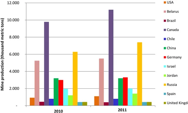
The first production of potassium was in former URSS, which is divided today by Belarus and Russia. Together they produced 10 of 28 Mt per year of K2O that was ascending the world’s potassium production (Consejo Superior de Colegios de Ingenieros de Minas de España, 1996) which nowadays is similar to these quantities.
A serious problem of European potassium productions is the dumping that those two countries made, so the necessity of facing it from European Union. The decreasing use of potassium by Russian and Belarus agriculture resulted in an excess of this mineral in Europe.
Nowadays, the first world potassium producer is Canada, followed by Russia and Belarus, with an annual production between 5 and 8 Mt of potash (U.S. Department of Energy, 2007). Canada has an important installed quantity, and thus can respond quickly to world’s variations potassium demand. In Figure 2.1 is listed potash world mine production, during the years of 2010 and 2011.
Figure 2.1 World mine production of potash during 2010 and 2011. Source: adapted from (U.S.
Department of the Interior, 2011).
2.000 4.000 6.000 8.000 10.000 12.000 2010 M in e p ro d u ction (t h o u san d m e tr ic to n s) 2011 USA Belarus Brazil Canada Chile China Germany Israel Jordan Russia Spain United Kingdom
Analyzing this chart (Figure 2.1) is notably seen that Canada is still leading the world’s production of potash which is one of the most consumed manufactured salts by the human population.
Potash is used primarily as an agricultural fertilizer because it’s a source for dissolved potassium and has a wide variety of mined and manufactured salts, all containing the element potassium in water-soluble form. Therefore, Potash, can have many different compositions, such as, potassium chloride (KCl), or muriate of potash (MOP), potassium sulfate (K2SO4), sulfate of potash (SOP), potassium/magnesium sulfate (K2SO4 + MgSO4) as known as sulfate of potash magnesia (SOPM), potassium nitrate (KNO3) and mixed sodium/potassium nitrate (NaNO3 + KNO3). The term potash was originally applied to potassium carbonate/potassium hydroxide crystals that were recovered in iron “pots” from leaching wood “ashes” with water (U.S. Department of the Interior, 1997).
Along this study the most important form of Potash will be considered to be potassium chloride, potassium sulphate and potassium nitrate, as they are the most common potassium salts used as heat transfer fluid (HTF) or thermal energy storage (TES) materials for CSP plants.
2.1.1 Mining sector in Catalonia, Spain
The beginning of the mining activity in Catalonia is connected to ancient times. Mining has always been present, on a more or less intense way, and contributes significantly for the development of Spain’s society.
The exploitation and production of potassium salts in one of the most important mining activities of Catalonia and Spain, and is presented in Table 2.1 for the period 1998-2001.
Table 2.1 Salt production evolution in Spain (units in tons). Source: adapted from (Federación
Minerometalúrgica de Comisiones Obreras , 2005)
Years 1998 1999 2000 2001 Salt Mining 2 062345 2 109150 2 068760 2 100000 Potash Mining 223885 316188 259704 219800 Total (Rock Salt) 2 286230 2 425338 2 328469 2 319800 Marine Salt 1 321059 1 400152 1 436345 1 420000 Spring Salt 92408 95346 105187 100000 Total (Marine and Spring) 3 699697 3 920836 3 869996 3 839800
Salt production has suffered a negative evolution between 1999 and 2000, and in 2001 a decrease on production is still observed, but not so significant according to the Mining Spanish Statistics (Federación Minerometalúrgica de Comisiones Obreras , 2005).
The potassium Catalonian basin, which extends through Barcelona and Lerida provinces, is among the most important of the world, containing large mineral reserves economically viable and is strategically located near Barcelona’s port with direct access to the important French market and other European markets through the Mediterranean Sea. This basin, on the beginning, was exploited through four subterranean mines: Suria; Cardona; Sallent; and Balsareny (all of them located on Barcelona’s Province).
The last two have been unified in the 70’s to become Potasas Del Llobregat mine. Meanwhile Cardona was closed facing the depletion of mineral reserves economically exploitable. So, until 1996 there were only two remaining in activity: Potasas Del Llobregat and Suria (Consejo Superior de Colegios de Ingenieros de Minas de España, 1996) and nowadays there’s just one potash mine in activity in Suria, because meanwhile Potasas Del Llobregat was closed facing also depletion of resources. During an International Seminar about mine closures, the main reasons for these closures were listed (Figure 2.2). The main reason for a mine closure was concluded to be depletion of mineral resource, as expected in mining sector during operation for several years, but also an important factor was observed to be related with high costs and low prices, respectively on the minerals extracted and produced for industrial sale.
The sodium salts produced in Catalonia are divided in marine salt, sub product exploitation salt from potassium salt mines and rock salt directly coming from mining exploitation (table 2.1). One part of the sodium salt that is obtained as sub product of potassium production is commercialized as industrial salt for the production of Chlorine and Soda in electrolytic processes. The quantity of sub product exceeds the market capacity, so residual salt is deposited in salt tailings next to potassium mines.
Sodium salts, for the abundant existing reserves in Catalonia, are being exploited under an inferior level they actually should be, but not only in this region, sodium salts are very abundant around all Spanish territory (Consejo Superior de Colegios de Ingenieros de Minas de España, 1996).
Indeed, Catalonian mining of sodium and potassium resources is not making enough efforts for salt revalorization, which is mostly intended to industrial uses for chlorine and soda production by electrolysis, as above-mentioned, when there’s a real possibility of producing salt for human consumption or for implementation to CSP plants.
The use of residual salts of mines as a heat transfer fluid and/or storage system has never been tested before and needs experience from the mining sector to prove its potential use on concentrating solar power plants as TES medium.
2.2 Characterization of residual salts available in mines
Salts can be classified in many different types with various chemical compositions, melting and freezing points and thermo-physical properties. The most common anions presented are chloride, fluoride, sulphate, nitrate and carbonate. Combining those salt based compositions with their characteristic minerals containing sodium, potassium, magnesium and calcium, the most usual and extracted salts from salt mining industries are obtained. Salts have indeed a variety of compositions, but the most frequent on salt mining industries are: chloride-based salts, such as sodium chloride (NaCl), potassium chloride (KCl), magnesium chloride (MgCl2) and calcium chloride (CaCl2); sulphate based salts, including sodium sulphate (Na2SO4) and calcium sulphate (CaSO4); and carbonate based salts as calcium carbonate (CaCO3).
From the point of view of residual salt availability of one mine in Catalonia, the higher quantities observed are CaSO4, NaCl, KCl and MgCl2, so these are potential residual salts to be used as HTF and TES, according to real data from residual salts in one Catalonian mine, provided by CTM.
Concretely, CaSO4 is coming mostly from residual Plaster which is a mineral formed by [CaSO4 + 2H2O]. In addition, MgCl2 is appearing also from a mineral but called Carnallite, which is formed by [MgCl2 + KCl + 6H2O].
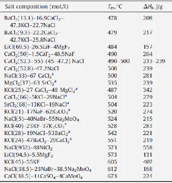
Comparing these compositions and reviewing the literature of high-temperature phase change and heat storage materials for thermal energy storage proposed by Kenisarin M. M. (2010), some salts are found along with their usual composition as heat storage and phase change materials compatible with the most common salts extracted.
Table 2.2 and Table 2.3 present several chloride salt compositions and the different melting temperatures of those compositions.
Table 2.2 Chloride eutectic salts compositions. Source: (Kenisarin M. M., 2010)
Some examples of chloride salts are [NaCl + KCl + MgCl2], [KCl + MgCl2 + NaCl], [MgCl2 + NaCl], [KCl + MgCl2], [CaCl2 + KCl + MgCl2 + NaCl] among many others.
In addition, hydroxide, nitrate and carbonate salts are found in Table 2.4 and Table 2.5, below.
Table 2.4 Hydroxides and nitrates salt compositions. Source: (Kenisarin M. M., 2010)
Table 2.5 Carbonates and some other salts compositions. Source: (Kenisarin M. M., 2010)
In those tables it’s observed the many different salts compositions and their melting temperatures, which are very important regarding the range of temperatures of a CSP plant.
2.3 CSP energy production technologies
The solar irradiation arriving at the Earth’s surface is an important renewable energy source. In a general point of view, solar irradiation, which is contained by photons, can be converted into electricity through Photovoltaic Systems or Concentrating Solar Power (CSP) systems. Along this thesis only CSP technologies are focused, which use mirrors or optical lenses and concentrate the sunlight to create a high energy density and temperature level. These types of systems can only work with direct solar irradiation, so they are more likely to be used in areas where there are few clouds because otherwise photovoltaic technologies would fit better (Barlev D. et al, 2011). A CSP plant is consisted by four main sub-systems including a concentrating system, a solar receiver, storage and/or supplementary firing (as a back-up system) and a power block. These sub-systems are linked together by transferring a suitable fluid or radiation. The function of the solar receiver is to absorb the concentrating solar energy and transfer it to the heat transfer fluid (HTF). The power block receives a high temperature heat from the heat transfer fluid and the storage tank storages solar heat coming from the transfer fluid. A scheme of the sub-systems of a CSP plant is shown in Figure 2.3:
Figure 2.3 Components and sub-systems of a CSP plant. Source: (EASAC, 2011)
Among the four existing technologies of Concentrating Solar Power (CSP) used to concentrate and collect sunlight in order to turn it into heat, these CSP technologies are divided in two groups: the ones that focus the sun rays to a line and the one that focus the sun rays to a point, as shown in Figure 2.4.
Figure 2.4 Different types of CSP technology. Source: (Gharbi N. et al., 2011)
A description of the main specifications of the four CSP technologies described in Figure 2.4 is made in Table 2.6, to better clarify and highlight the main differences of operating temperatures range of each technology and the current relative costs, maturity level and concentration ratios.
Table 2.6 Description and specifications of CSP technologies. Source: adapted from (Barlev D. et al,
2011)
Technology Operating temp. range (ºC)
Relative
cost Concentration ratio Technology maturity
PTC 50-400 Low 15-45 Very mature
LFR 50-300 Very low 10-40 Mature
CTR 300-2000 High 150-1500 Most recent
PDC 150-1500 Very high 100-1000 Recent
2.3.1 Parabolic Trough Collectors
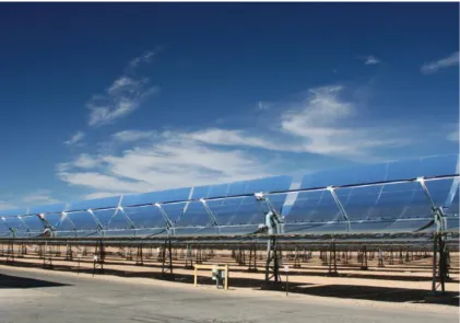
The parabolic trough collectors (PTCs) became the most implemented concentrating solar power technology nowadays. Since the 70’s this technology has been installed in solar central facilities for generating electricity and providing thermal energy at an average temperature appropriate for industrial processes. On the second half of the 80’s nine thermo solar centrals were built in California, with a total installed power of 354 MWe, based on parabolic trough collector’s technology; they worked satisfactorily during 15 years (Cohen G.E., 1994) and continue working without major technical problems. These thermo solar plants comprehend a storage system, usually with oil. In Figure 2.5 is shown the collector field of one SEGS (Solar
Concentrating Solar Power
Line Focusing Point Focusing
Parabolic Trough Collectors (PTC) Linear Fresnel Reflectors (LFR) Central Tower Receiver (CTR) Parabolic Dish Collector (PDC)
Electric Generating System) in California (NextEra Energy, Inc., 2012). Analyzing the picture beneath, is possible to see the constitution and structure components of a PTC: an absorber tube, a curved mirror, and pipes containing the HTF.
Figure 2.5 Collectors Field of a thermo solar plant with parabolic trough collectors in California
(SEGS). Source: (NextEra Energy, Inc., 2012)
After 15 years of operation of these thermo solar plants, i.e., around the 90’s, it was a starting point to implement these technologies in other parts of the world. The operation and maintenance costs have been continuously reducing and the annual production of electricity has been increasing while earning experience in operation of this type of thermo solar plants (Cohen G.E., 1994; Kearney D.W., Cohen G.E., 1996; Cohen G.E., et al, 1998). Until today, most of the PTC fields installed for commercial applications are using thermal oil as a working fluid of the solar field. Besides having a considerable cost, this oil has a serious limitation over the efficiency of the thermo solar plant. In fact, the used oil is degraded when it reaches high temperatures, and so it’s not possible to operate over 390 ºC with these collectors, which limits the maximum temperature of the turbine vapor cycle to 370 ºC.
On the other hand, the restrictions of transfer processes in heat exchangers and thermo physical properties of the heat transfer fluid makes the pumping bomb, which carries about the distribution of oil in the solar field, to have also a considerable energetic consumption and a reduced efficiency due to the high average temperatures of the oil.
Parabolic trough collectors are a technology which has reached its level of maturity in prototype applications and an excellent performance in commercial power plants for energy production, with very positive results. However, and so far, there are three other concentrating solar power technologies using the same energy source (the sunlight) with
other characteristics, using different transfer and storage fluids, different storage technologies and having also different characteristics, costs and efficiencies. They will be described in the following sections.
2.3.2 Linear Fresnel Reflectors
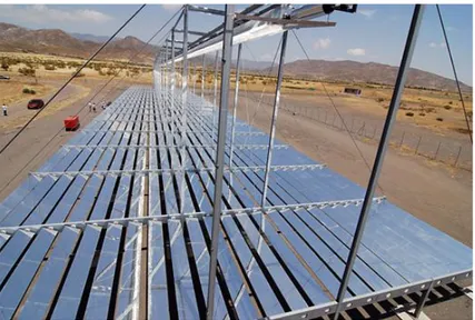
Linear Fresnel Reflectors are quite similar to PTCs technology because they are characterized by a linear receptor in which the incident radiation is concentrated (line focusing - Figure 2.4). LFR incorporates however long arrays of flat mirrors that concentrate the light onto a linear receiver, which is mounted on a tower suspended above and along reflector arrays (Figure 2.6). A disadvantage of LFR technology is the fact of being more recent when compared to the PTC historical record, but analyzing studies and prototypes meanwhile developed, puts into evidence that there are many advantages when compared to PTC.
In fact, the design of a LFR is cheaper than a PTC due to the flat and elastic nature of the mirrors used. Not considering it as a disadvantage, but a challenge, the light blocking between adjacent reflectors needs a solution as it requires more space between mirrors, which occupies more land, as well as the tower receiver height needs to be increased, causing additional costs.
One of the first prototypes of a LFR demonstration was implemented on the Plataforma Solar de Almeria (PSA), in Spain, where it took its first steps (Plataforma Solar de Almería, 2008-2009). As demonstrated below, a prototype of a LFR in PSA is composed by curved mirrors, absorber tube and re-concentrator.
Figure 2.6 Linear Fresnel demo reflector erected on the Plataforma Solar de Almería (PSA). Source:
Concluding, LFR technology has many advantages when compared to PTCs concerning the lower investment, maintenance and operation costs required, the inexistence of metal-glass welds at the ends of each receiver tube module for maintaining vacuum within the outermost tube, and do not uses rotating joints (Häberle A., et al, 2002). Admitting the lack of commercial and experimental applications with LFR, PTC technology has a big advantage of being already validated. Despite of these aspects and analyzing previous studies, LFR can also be easily coupled to direct steam generation as well as to molten salts for thermal energy storage and HTF.
This is the reason why the next step for LFR technology should be a pilot plant under real commercial operation conditions because previous studies and experiences have demonstrated a wide potential on LFR technology and results for reaching a higher level of efficiency than any other CSP technology.
2.3.3 Parabolic Dish Collector (Stirling engine)
A Parabolic Dish Collector (PDC) consists on a parabolic mirror of big diameter with an external combustion Stirling engine located at its focal area. The parabolic mirror (dish) does a continuous solar tracing, and the sun’s rays are reflected at its focal plan.
The Stirling engine is an external combustion engine which also uses a Stirling thermodynamic cycle and has two aspects that makes it more adequate for this application: i) energy intake can be done through collected sunlight from the parabolic dish and concentrated at its focal area and ii) very high efficient thermodynamic cycle.
The well-known PSA has contributed in a very positive manner for this type of technology with three projects, namely: Distal I, Distal II and EuroDISH (Plataforma Solar de Almería, 2008-2009). In Figure 2.7 is shown the result of the EuroDISH project where Spain and Germany were involved to develop new prototypes of PDCs with a Stirling engine.
The heat loss of these systems is a highly important and incompletely solved issue and, for the moment, only few literature studies report trials to work through the convection heat loss mechanisms of cavity receivers with no-wind conditions (Leibfried U., Ortjohann J., 1995; Taumoefolau T., Lovegrove K., 2002; Paitoonsurikarn S., Lovegrove K., 2006) and free-forced convection heat loss mechanisms under wind conditions. Four types of receivers shaped in cubical, rectangular, cylindrical, and hemispherical forms have been investigated, both experimentally and numerically. Numerous studies have been published on square and rectangular open cavities due to their wide applications in various engineering systems, in addition to those in solar thermal receivers. On the contrary, fewer studies of predicting convection heat loss for cylindrical and hemispherical cavity receivers have been undertaken (Prakash M., et al, 2009).
The innovation in PDC technology has promoted this highly efficient but expensive technology to become reasonably affordable. However, PDCs are heavy and expensive structures that must track the sun very accurately to fulfill their maximum potential. The use of heat engines and high energy conversion cycles makes their energy production very efficient and compensatory because they do not require the use of any heat transfer media.
Apart from all these positive aspects there’s a crucial negative one: PDCs cannot be easily linked with thermal storage media, especially when the concern is to implement them in large solar power energy production plants for commercial scale, so maybe this option would fit better at a smaller scale production and instantaneous consumptions.
2.3.4 Central Tower Receiver
The development of thermo solar plants with Central Tower Receivers (CTRs) has started around the 70’s, as well as PTCs, and during 25 years they were implemented and tested as demonstration models in many countries around the world, particularly in the USA, Spain and Israel (Radosevich L.G., 1988; DeLaquil P., et al, 1991; Avellaner J., et al, 1985).
The first experiences of CTRs were focused on building and operating centrals of 10 MWe connected to the electric network in the California, USA, named as Solar One and Solar Two. The Solar One central was in operation from 1982 till 1988 and was formed with an exterior receptor that used water vapor, which could be directly addressed to a turbine vapor cycle or through numerous heat exchangers, TES with oil, sand and gravel for its later use in the power cycle. Another project, more recent, was Solar Two, which was operating from 1996 till 1999. This thermo solar plant was a reconversion of the Solar One to work with molten salts as HTF.
However, these thermo solar plants of CTR didn’t have the chance of experimenting themselves in commercial applications as the PTC in California did.
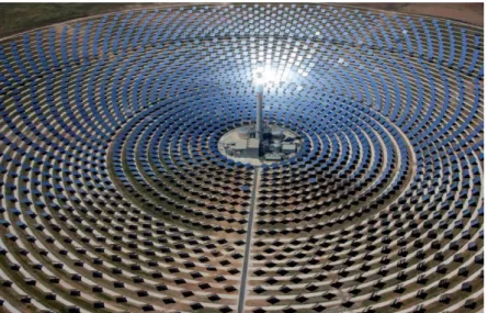
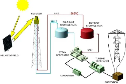
After those projects, Solar Tres was developed between 2002 and 2008, based on Solar Two experience, but with the goal of building a demonstration plant at commercial scale, able to produce 17 MW of nominal power from solar energy with a TES with molten salts (Plataforma Solar de Almería, 2008-2009). Solar Tres was used mainly to innovate and validate some technological options and to boost the most recent project, Gemasolar, considered to be the first commercial plant in the world with heliostats, central tower and molten salts receiver and storage fluid with a nominal power of 20 MW. It was inaugurated on October of 2011 in Seville, Spain (Torresol Energy Investments, S.A., 2011), and is illustrated in Figure 2.8.
Figure 2.8 Gemasolar Solar Thermal plant using CTR technology with molten salts storage system.
Source: (Torresol Energy Investments, S.A., 2011)
Amongst all of the advances achieved, the most significant of Gemasolar are the capability to store energy (and so to have it available when users need it) and the capacity to operate at very high temperatures, achieving greater energy efficiency than any other conventional system. This system allows a continuous production of electricity up to 15 hours in absence of sunlight, guaranteeing the supply of electricity for around 6600 hours per year, which can still be adapted to user consumption demand.
The operation process consists in capturing sunlight by heliostats and reflecting it towards the receiver. In the receiver salts heat up and descend to the hot salt storage tank where they are stored at up to 500 ºC. From the hot salts tank, salts are transferred to heat exchangers through pipes and when they lose their heat they yield a steam that will move a turbine for the coupled generator, producing electrical energy (Torresol Energy Investments, S.A., 2011). Central Tower Receiver technology has greatly improved over the last few decades, and continues to draw much attention as suitable scheme for large solar thermal plants. The
energy efficiencies. The only obstacle for this technology is the high initial investment necessary for construction and maintenance costs, so further technological advancements in efficiencies must be followed by low cost materials and storage schemes for this CSP system becoming less expensive, more competitive and mature compared with PTC (the most mature technology nowadays).
2.4 World current status of CSP market
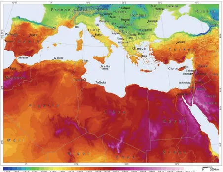
From a European and Mediterranean perspective and analyzing direct normal irradiation (DNI) potential, two promise countries are easily identified in Europe for the development of thermal solar energy plants, namely as Spain and Portugal. In North Africa region there’s Morocco, Algeria, Libya and Egypt and in the Middle-East there’s Saudi Arabia, Israel and Jordan as potential countries to install these solar-based systems (Figure 2.9). Among all these countries, Spain is the number one in CSP plant investment and solar energy production, and unfortunately Portugal, despite of its potential, has almost not invested in CSP technology. For political and economic reasons, many Middle East and North Africa (MENA) countries are far behind Spain, which is, as mentioned, the leader solar thermal energy world producer and pioneer in Europe and Mediterranean regions. On the other hand, USA is the world leader due its strong investments in CSP technology and other new projects.
Figure 2.9 Direct normal irradiation potential for Southern Europe and Mediterranean regions.
Source: (GeoModel Solar s. r. o., 2010)
There’s a long challenge on developing CSP technology in MENA countries, where the DNI available becomes an important waste regarding all the thermal energy possible to convert in
electricity from its high levels of irradiation. But the most important for these populations is certainly not developing and investing in CSP plants at this moment, and especially during all the conflicts happening in Libya and Egypt, and so political issues and economic instability of those countries are thus a priority.
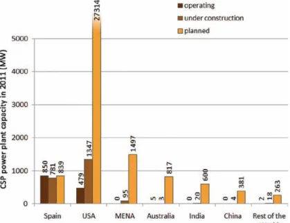
A global view of CSP plant planned, operating and under constructing is shown in Figure 2.10 where it can be seen the higher power capacity operating CSP plants in Spain, with two times the power capacity of the USA. However, due to the investments made in the USA and the current construction of new CSP plants, they will quickly produce more power than any other country in the world. But in Europe and as a consequence of the DNI potential in Iberian Peninsula, Spain has invested significantly in thermal energy production during last year’s. So, this country became revolutionary using a brand new system employing only molten salts as TES media applied to CTR technology for commercial electricity production; as previously referred, it is noteworthy the Gemasolar Plant project inaugurated last year located in Seville. Today, Spain is the world leader in installed power and technological capacity, and companies of the solar thermo electrical sector are starting to participate in ambitious projects in many regions of the world (USA, North Africa, Middle-East, China, India and Australia). Besides the ones which are operative, 60 new plants are expected to be in operation, which together will sum up around 2500 MWe of installed power in Spain according to Protermosolar informations available online (Protermosolar, 2011). Lamentably, Portugal doesn’t have any CSP plant in commercial scale production and since 2007 is making efforts for developing a CSP pilot-plant demonstration based in LFR technology in Southern Portugal (Tavira, Algarve), developed by Algarve University and INETI (Silva A., 2010).
In MENA countries, projects and investments in many different CSP plants are proposed, but just a few are under construction. It is desirable that they start operation as soon as possible because MENA countries are the regions that have more DNI and land for construction available. Thereby, there is a long path for innovation and improvements, but the four important areas where it should be focused are energy efficiency, supply capacity, cost reductions of construction and materials used and environmental sustainability.
2.5 Characterization of heat transfer media and storage fluids
2.5.1 Types and properties of heat transfer media and storage fluidsThere are many existing options of heat transfer fluids and thermodynamic cycles. The most used as heat transfer fluids are synthetic oil and saturated steam in commercial plants, while molten salts and superheated steam are coming to the market. Use of air (at ambient pressure or pressurized) and other pressurized gases (for example, CO2 and N2) are under development, while helium or hydrogen are exclusively used in Stirling engines with parabolic dish systems (EASAC, 2011). Molten salts are the only commercial option nowadays for storing during extended periods of time (between 8 and 15 hours), allowing electricity production to better match demand, while steam is more appropriate for short time (less than 1 hour) storage. Thermodynamic cycles are currently steam Rankine cycles, and Stirling cycles for parabolic dish collectors. Brayton cycles are under development, where a gas turbine is driven by pressurized gas heated by the solar collector. The combination of Brayton cycle that supplies its waste heat to a bottoming Rankine cycle promises the best efficiency and thus the highest electrical output per square meter of collector field (EASAC, 2011).
Meanwhile, the four CSP technology systems and technical options (mainly differing according to the heat transfer fluid used) are listed in Table 2.7. For parabolic troughs collectors, an emergent additional option is the use of compressed gas as the heat transfer fluid and molten salt for storage. However, this option is at a very early stage of development and efficiency data are not yet available. Nevertheless, the use of molten salt as a HTF and storage system is yielding excellent results, as provided by Gemasolar plant system based only on molten salts. The big call of TES using molten salts is to improve their capacity for storage during more than 15 hours according to different weather conditions along the year, so that CSP can be implemented in many other countries where the level of DNI is not that high as in MENA countries. The most common salt based compositions are chloride, fluoride, sulphate, nitrate and carbonate. Combining those salt based compositions with their characteristic minerals containing sodium, potassium, magnesium and calcium, the most usual and extracted salts from salt mining industries are obtained.
An engineering study was carried out to evaluate a concept, where another (less expensive) liquid medium, such as molten salt, is used as storage medium rather than the HTF itself. Detailed performance and cost analyses were conducted to evaluate the economic value of this concept. Since the salt storage was operated successfully in the Solar Two project in California and Solar Tres in Spain, no major barriers were identified to realize this concept in the first commercial parabolic trough power plant (Herrmann U., et al, 2004).
If molten salts can be more and more applied to Parabolic Trough Collectors and Central Tower Receivers, it could be a huge step for becoming a revolutionary storage system, because PTC and CTR are the most mature technologies at commercial scale production. So far there are many prototypes using molten salts as HTF and storage system, but just a few are effectively being applied commercially. Even so, molten salts provides numerous advantages when compared to other storage and HTF concerning specially their costs and the fact that a residual salt provided by the mining sector can be employed, which can be reused in thermo electrical solar plants to fill a storage tank and/or as a heat transfer fluid.
Table 2.7 Technical options regarding the use of heat transfer fluids / storage fluids for each CSP
technology family. Source: adapted from (EASAC, 2011)
CSP technology Technical options
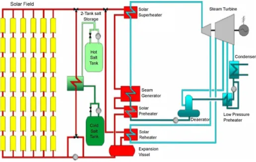
Parabolic Trough Collector (PTC)
PTC-oil: oil as HTF and molten salt storage PTC-SHS: superheated steam as HTF PTC-MS: molten salt as HTF and storage Linear Fresnel Reflector (LFR) Fresnel SaS: saturated steam as HTF Fresnel SHS: superheated steam as HTF
Central Tower Receiver (CTR)
CTR-SaS: saturated steam as HTF CTR-SHS: superheated steam as HTF CTR-MS: molten salt as HTF and storage CTR-AR: ambient pressure air as HTF and Rankine cycle
CTR-GT: pressurized air as HTF and Brayton cycle
CTR-SC: supercritical cycle
CTR-CC: pressurized air as HTF and combined cycle
Parabolic Dish Collector (PDC) PDC: helium or hydrogen Stirling cycle
2.5.2 Composition of heat transfer and storage fluids
There are many types of thermal energy fluids used such as oils, salts, helium, hydrogen and steam that can be used as a HTF or storage system depending on which CSP technology is to be implemented and storage system required, as detailed in the previous section.
The composition of oils can be divided in three types: mineral, synthetic and silicone oil. Mineral oil is any of various colorless, odorless, light mixtures of alkynes from a non-vegetable source, particularly a distillate of petroleum (Erhan S. Z., et al, 2005). Synthetic oil is a lubricant consisting of chemical compounds that are artificially made such as polyalphaolefin (Jantzen E., 1996). Silicone oil is any polymerized siloxanes with organic side chains such as polydimethylsiloxane (Miyahara H., et al, 2006).
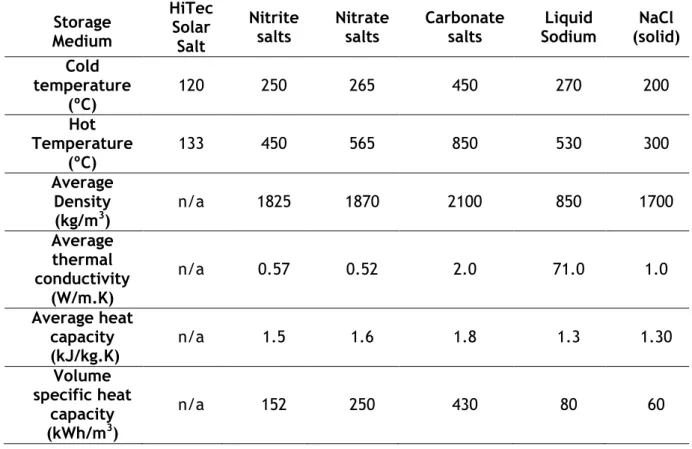
Salt is a mineral mainly consisted of sodium chloride, but it may include other anions such as nitrates, chlorides, carbonates and sulphates, while molten salt is the salt in its liquid state considered to as class of ionic liquid.
Steam is water vapor in its technical mean and represents the gaseous state of water, which is produced when the water reaches its boiling point. Detailed characteristics and properties of some of those fluids are given in Table 2.8 and Table 2.9, where are particularly considered the cold and hot temperatures, the average density, the average thermal conductivity, the average heat capacity and the volume specific heat capacity, because these are the most important thermo-dynamic properties of interested for the designed applications.
Table 2.8 Thermal storage oils and their properties. Source: adapted from (Barlev D. et al, 2011)
Storage Medium Mineral Oil Synthetic Oil Silicone Oil Cold temperature (ºC) 200 250 300 Hot temperature (ºC) 300 350 400 Average Density (kg/m3) 770 900 900 Average thermal conductivity (W/m.K) 0.12 0.11 0.10 Average heat capacity (kJ/kg.K) 2.6 2.3 2.1 Volume specific heat capacity (kWh/m3) 55 57 52