Evaluation of durability and resistance of steel anchorages
in masonry walls
PINHO, FERNANDO
1; LÚCIO, VÁLTER
2; MOURA, LUÍS
3; TRAVASSOS, NUNO
4;
ALMEIDA, INÊS
5ABSTRACT:
Long and short steel anchorages are often used in the strengthening of rubble stone (heterogeneous) masonry walls. At design stage it is important to predict mechanical behaviour and durability of such anchorages, used for rehabilitation of masonry buildings.This paper presents the results of a study related to an anchoring system, developed by the Portuguese company ZIRCOM Engenharia S.A., carried out on different masonry specimens built up for this purpose. The results include the analysis of durability aspects and mechanical behaviour (observed in pull-out tests) of long and short anchorages embedded in masonry.
This study has been developed at Faculdade de Ciências e Tecnologia of Universidade NOVA de Lisboa (FCT-UNL), since January 2012, on request of ZIRCOM Engenharia S.A., and with the participation of A2P Consult, Ltd, a Portuguese design and consulting company.
Keywords: Masonry wall, anchoring system, durability, resistance
NOTATION
ZAS Zircom Anchorage System; Ai anchorage i;
Bi masonry block i; Ci masonry corner i; c core drill diameter;
v steel bar diameter;
ceff effective cover;
cnom nominal cover.
1 INTRODUCTION
Structural rehabilitation of ancient buildings aims the improvement of local or global performance in order to satisfy functional standards, often more demanding than the original ones. It usually involves the retrofit and strengthening of existing masonry walls. The use of steel rebars anchorages is a
traditional solution, used not only as reinforcement of the material itself but also to improve the connection between different structural elements 1. These anchorages can be passive or active tensile elements. Passive anchorages do not change the “balance” of forces in walls and they are activated with the change of balance caused by seismic actions or new loads. Active anchorages (prestressed bars) change the “balance” of the structure and masonry stresses. This type of anchorage allows a better control of deflections and cracking and an increase of the bearing capacity of the masonry walls 2.
Anchorages can be used with different purposes: i) to connect new structural elements to the walls (generally short anchorages within the thickness of the wall, see Figure 1.a); ii) to strengthen the connection between orthogonal walls, typically at corners (see Figure 1.b, 1.c and 1.d) or in the connection of interior walls, to improve bracing and thus a tridimensional behaviour; iii) to connect parallel walls (Figure 1.e) or iv) to bond walls with severe cracks 2. The global behaviour of the different structural elements is fundamental to a better performance regarding static loads, foundation settlements and dynamic loads as earthquakes. The strengthening for new openings and the connection between orthogonal walls, walls/floors and walls/roof are some examples, Figure 1.
(a) masonry wall strengthened with concrete cover, connected by short anchorages; (b) steel anchorage in corner; (c) niche in masonry stone led to the removal and reapplication of the stone; (d) long anchorages in the façade of Bank of Portugal headquarters, Lisbon; (e) movement compatibilization of parallel walls by opening of voids, in Ivens Street, Lisbon; (f) confinement of walls which support vaulted structures by means of long anchorages, in Bernardas Convent, Tavira.
2 OBJECTIVES OF EXPERIMENTAL PROGRAM
The overall project in progress at FCT-UNL includes, at this time, two parts:
i. a first set of tests to check the quality/durability of the implementation of long anchorages, by assessing the cover thickness of the steel element down the holes, supplementing the first results
Figure 1. Examples of short and long anchorages used to strength ancient masonry walls
Short Anchorages Niche
Steel plate and anchor
Existing masonry wall
Steel plate
Concrete cover
(a) (b) (c)
(d) (e) (f)
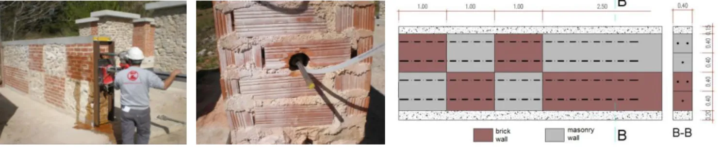
reported in 2012 [3]. For this, a wall consisting of sections of rubble stone and brick masonry was built and the ZAS - Zircom Anchorage System was applied. The system consists on inserting a steel bar, with an elastic sleeve, inside holes drilled in the masonry, and the injection of the sleeve with grout. The sleeve is used to prevent the leakage of grout in case of voids in the masonry. The system is supplied pre-assembled. After the execution of the anchorages, the wall was cut on several vertical sections and the grout cover of each steel bar was analysed;
ii. in a second set of tests the performance of the ZAS system in terms of its mechanical resistance is analysed, using pull-out tests on bars with different lengths. In particular, the tests regard the failure modes and the maximum pull-out strengths. For this purpose, stone, brick and mixed (stone-brick) masonry specimens were performed.
3 MASONRY SPECIMENS
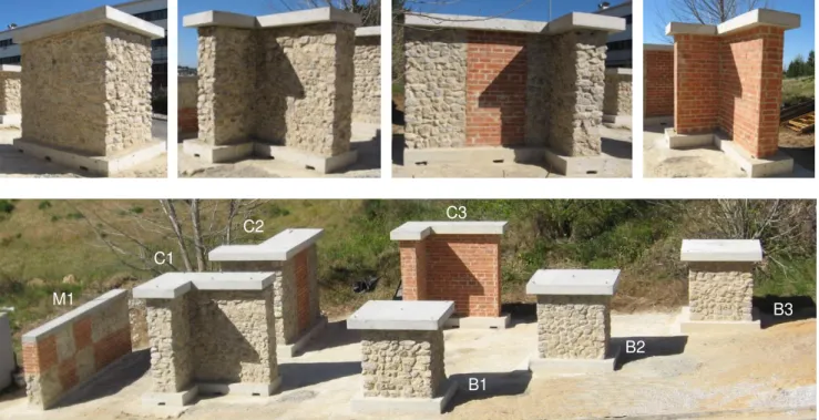
For the present study seven stone, stone-brick and brick wall specimens were built in the FCT-UNL. One of these specimens (M1) was used to assess the durability conditions of ZAS [3]. The remaining six specimens, blocks B1 to B3 and corners C1 to C3, with different geometrical shapes, were used to assess the mechanical behaviour of the referred system.
The specimens were built with rubble stone and brick masonry [4, 5]. The former was made with lime stone with a maximum length of about 0.30 to 0.35 m, and the others with clay brick with 22x10.5x7 cm. The specimens were built on reinforced concrete bases, with 0.20 m thick, and a concrete lintel, with 0.15 m thick, was cast over the specimens. To reproduce the effect of vertical compression on the masonry walls, a vertical load was applied before the pull out tests on specimens B1 to B3 and C1 to C3.
Stones and bricks were laid with natural hydraulic lime mortar, having a volumetric composition of 1:3 (hydraulic-lime:sand), using river sand and yellow pit sand in equal parts. The joints of the brick masonry have a thickness of about 1 cm. The mortar average spreading [6] was about 62% and the average strength at the age of 28 days was 1.5 MPa (dry cure) and 2.2 MPa (wet cure) [7]. The threaded steel bars (M16) have an average yield tensile force of 116.2 kN and a tensile resistance [8] of 128.1 kN.
3.1. Wall built to evaluate durability aspects (M1)
For the tests to check the position of the anchorages, a specimen wall (M1) it was built in January 2012, consisting of alternating sections of stone and brick masonry, Figure 2.
Three months after the construction of wall M1 (March 2012), the ZAS anchorages were executed and the wall was cut into several vertical sections (about three sections per meter), using a saw disc, to analyse the position of the steel bars (Figure 3).
3.2. Walls built to evaluate mechanical behaviour (B1 to B3 and C1 to C3)
The construction of these wall specimens took place in January and February 2012. Figure 4 shows pictures of the wall specimens with the lintels and an overview of the seven specimens, including specimen M1.
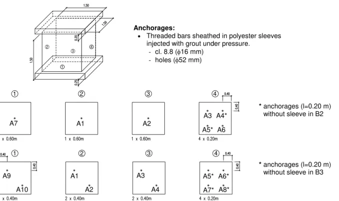
52 mm diameter holes were drilled in specimens B1 to B3 and C1 to C3, according to the distribution shown in Figures 5 and 6. Table 1 shows the lengths of the holes. To facilitate the reading some cells in Table 1 are coloured according to the anchorages length.
Figure 3. Sectioning the wall specimen M1 [3].
Figure 4. Individual and global view of the seven specimens used in the work. M1
C1
C2 C3
B1
B2
1
2 4
3
1 2 3 4
1 2 3 4
Figure 5. Distribution of anchorages in each façade of walls B1 and B2 (above) and B3 (below)
Figure 6. Distribution of anchorages in walls C1 (above), C2 (middle) and C3 (below).
A7 A1 A2 A3 A4*
A5* A6
A9 A5* A6*
A7* A8* A10
A1 A2
A3 A4
* anchorages (l=0.20 m)
without sleeve in B2
Anchorages:
Threaded bars sheathed in polyester sleeves injected with grout under pressure.
- cl. 8.8 (16 mm) - holes (52 mm)
A3 A1 A2
A3 A1 A2
A3 A1 A2
* anchorages (l=0.20 m) without sleeve in B3
A3 A1 A2
A3 A1 A2
Table 1. Anchorages in wall specimens C1 to C3 and B1 to B3
Anchorage
Length [m]
B1 B2 B3 C1 C2 C3
A1 0.60 0.60 0.40 2.00 3.00 2.00
A2 0.60 0.60 0.40 2.00 3.00 2.00
A3 0.20 0.20 0.40 2.00 3.00 2.00
A4 0.20 (*) 0.40 -- -- --
A5 0.20 (*) (*) -- -- --
A6 0.20 0.20 (*) -- -- --
A7 0.60 0.60 (*) -- -- --
A8 -- -- (*) -- -- --
A9 -- -- 0.40 -- -- --
A10 -- -- 0.40 -- -- --
(*) – anchorage without sleeve
After the execution of the anchorages, in November 2012, a vertical load was applied in each wall (December 2012), to install global stress about 0.5 MPa, Figure 7. The pull-out tests were carried out on the following dates: April 2013 for walls C1 to C3 and July 2013 for walls B1 to B3.
4 EXPERIMENTAL RESULTS
4.2. Durability aspects (M1)
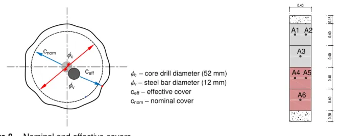
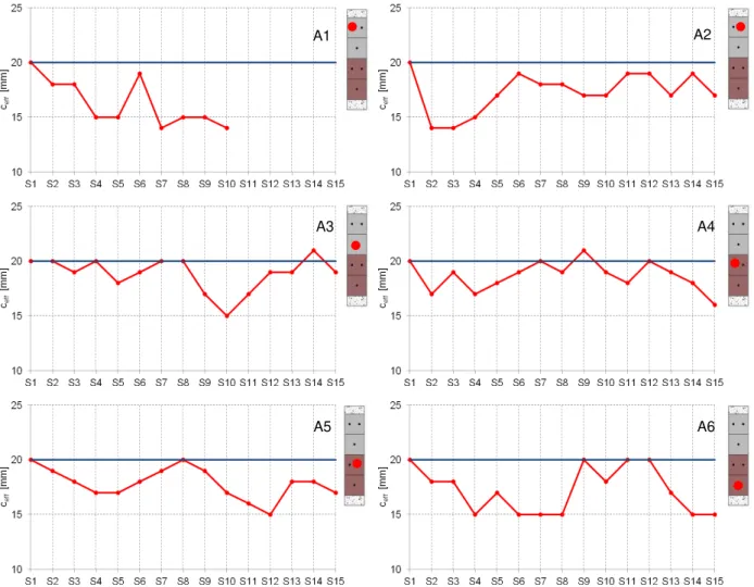
The grout cover thicknesses of the steel bars were registered in anchorages A1 to A6 of specimen M1, in vertical sections S1 to S15 (spaced about 0.30 m, see Figure 3), as presented in Figure 8. In these sections the effective cover, ceff, was measured, i.e. the distance between the bar and the
boundary of the hole (edge of grout).
The cover to be specified by the designer, nominal cover, cnom, shall be the sum of the minimum
cover (cmin) with the tolerance resulted from the technology used, c, as presented in Equation 1:
c
c
c
nom
min
(1)The minimum allowable cover at site, cmin, shall be defined as a function of the design working life
of the structure, the environmental conditions and the characteristics of the grout, i.e., its ability to protect steel against corrosion [9].
For a given bar diameter (v) and core drill diameter, c, the nominal cover, which is a theoretical
value, is given by the distance between the surface and the theoretical limit of the bar hole (see Figure 8), as presented in Expression 2:
2
c
c vnom
(2)In the present study, a core diameter c = 52 mm and a bar diameter v = 12 mm were used,
resulting cnom = 20mm.
Figure 9 shows the values measured in each anchorage, in sections S1 to S15. To facilitate the reading, schemes of the walls are included, indicating the anchor identification. These graphs and Table 2, where values of ceff are listed, it shows that the effective cover is, in general, smaller than the
nominal cover. The deviation of the actual value of the cover from the nominal value arises mainly from two factors: (i) the position of the bar does not correspond generally to the centre of the hole; and (ii) the drilled hole does not have a perfectly circular section and is larger than the cross section of core drill. While the first factor reduces the effective cover, the second factor tends to increase it. Some values of anchorage A1 were discarded due to defects in the grout injection.
Figure 8. Nominal and effective covers v
c cnom
ceff c – core drill diameter (52 mm) v– steel bar diameter (12 mm)
ceff– effective cover
cnom– nominal cover
A1
A3
A4
A6 A2
Table 2. Effective cover values along anchorages A1 to A6 in specimen M1.
Anchorage
Effective cover ceff[mm]
S1 S2 S3 S4 S5 S6 S7 S8 S9 S10 S11 S12 S13 S14 S15
A1 20 18 18 15 15 19 14 15 15 14 --- --- --- --- ---
A2 20 14 14 15 17 19 18 18 17 17 19 19 17 19 17
A3 20 20 19 20 18 19 20 20 17 15 17 19 19 21 19
A4 20 17 19 17 18 19 20 19 21 19 18 20 19 18 16
A5 20 19 18 17 17 18 19 20 19 17 16 15 18 18 17
A6 20 18 18 15 17 15 15 15 20 18 20 20 17 15 15
Table 3 presents the values of the deviation of the effective cover in relation to the nominal value. Based only on these values, it may be concluded that the average value of the deviation is 2.4 mm, with a standard deviation of 1.9 mm. Considering a tolerance (c) equal to the upper characteristic
Figure 9. Effective cover along anchorages A1 to A6 in specimen M1.
A1 A2
A3 A4
value of the deviation from the nominal cover, i.e., the deviation that has a probability of being exceeded only in 5% of cases, the value obtained is c = 5 mm.
Table 3. Effective cover deviation in relation to the nominal value
Anchorage ci = cnom - ceff,i [mm]
S1 S2 S3 S4 S5 S6 S7 S8 S9 S10 S11 S12 S13 S14 S15
A1 0 2 2 5 5 1 6 5 5 6 --- --- --- --- ---
A2 0 6 6 5 3 1 2 2 3 3 1 1 3 1 3
A3 0 0 1 0 2 1 0 0 3 5 3 1 1 -1 1
A4 0 3 1 3 2 1 0 1 -1 1 2 0 1 2 4
A5 0 1 2 3 3 2 1 0 1 3 4 5 2 2 3
A6 0 2 2 5 3 5 5 5 0 2 0 0 3 5 5
3.2. Pull-out tests
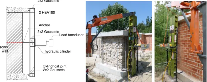
The pull-out tests were performed based on the test layout shown in Figure 10, where two pictures of tests are also presented.
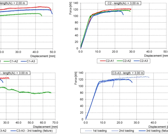
The load-displacement diagrams resulting from these tests are shown in Figures 11 and 12. In relation to the masonry blocks (short anchorages), the diagrams are represented by the anchorage length: 0.20 m, 0.40 m and 0.60 m. Regarding to walls C1 to C3 (long anchorages), the diagrams are shown per wall, given the specificity of the wall and the equal length of the bars. The maximum values of the forces for all anchorages are presented in Figure 13.
In what concerns to the anchorages with 0.20 m length (Figure 11), the failure is quite erratic because, due to the heterogeneity of the masonry walls, the small length of the anchorage will intersect different material conditions for different anchorages. The failure of these anchorages does
Figure 10. Test layout used in the pull-out tests of wall specimens B and C.
2x2 Goussets
2 HEA180
Anchor 3x2 Goussets
hydraulic cilinder Load tansducer
2x2 Goussets Masonry
wall
not occur by bonding between the bar and the injection grout, but as a tensile failure of the injection grout and the surrounding masonry.
In the case of the anchorages with lengths of 0.40 m and 0.60 m, the failure occurred in general by bonding between the bar and the injection grout, with much higher failure forces than in the shorter anchorage cases (See Figures 11 and 13). The mean values of these bonding stresses were 3.67 MPa and 3.08 MPa, with coefficients of variation of 0.27 and 0.23, respectively for the lengths of 0.40 m and 0.60 m. Considering a mean value for the bond strength of 3.0 MPa and a mean yielding force for the 16 mm threaded steel bars of 116.2 kN, it may be said that for anchorages shorter than 0.77 m it is quite probable that the failure occurs by bonding between the bar and the injection grout rather than by yielding of the bar. These values depend mainly on the mechanical characteristics of the injection grout, the bar tensile resistance and of the surface bonding characteristics of the bar.
For the longer anchorages (Figures 12 and 13) the failure occurred by axial tension of the threaded bars. Although the testing conditions in the anchorage tests are not equal to a tensile test of bars, since some eccentricities are induced in the bars that do not take place in the standard tensile tests, the mean value of the failure load of the longer anchorages is 117.9 kN, comparable to the mean yielding force and tensile resistance of the 16 mm threaded steel bars (116.2 kN and 128.1 kN, respectively). In these anchorages tests (Figure 12) it is also quite evident the large ductility of the failure mode, denoting that this failure relies on a ductile material (steel) rather than brittle materials as masonry and injection grout (Figure 11).
Figure 11. Force-displacement diagrams of tests on specimens B1, B2 and B3 with
5 CONCLUSIONS
Long and short steel anchorages of the ZAS - Zircom Anchorage System, used for the rehabilitation of masonry walls, were analysed in terms of durability aspects and mechanical behaviour.
For the durability aspects the aim of the work was to analyse the deviations of the grout cover to
Figure 12. Force-displacement diagrams of tests on specimens C1, C2 and C3 with
anchorages lengths of 2.0 m and 3.0 m.
and rubble stone masonry. Regarding this subject, it was found that the upper characteristic value of the cover deviation in the tested anchorages was about 5 mm.
The mechanical tests on short anchorages with 0.20 m long revealed that failure may occur by tension of the grout and masonry, with low resistance, scattered values and brittle failure mode. For these reasons, it is concluded that anchorages with less than 0.40 m should be avoided.
The anchorages with lengths of 0.40 m and 0.60 m presented failures by bonding between the injection grout and the threaded bars with a mean bond shear resistance of 3.0 MPa. For the M16 bars used in the tests, it was found that this kind of failure is quite probable to happen for anchorages shorter than 0.77 m without yielding of the steel bars. This anchorage length was obtained using the mean values of the mechanical characteristics of the grout and steel bars, and also depends on the surface bonding characteristics of the bar.
Ductile failures were obtained on the tests of the longer anchorages, where the failures loads tend to the values of the failure load in tension of the M16 threaded bars. Anchorages longer than 0.77 m shall be chosen, if a ductile behaviour, relying on the steel yielding, is needed for safety and integrity reasons.
ACKNOWLEDGEMENTS
The authors express thanks to Engineer Pedro Daniel Mendes Freire (from Zircom, SA) and to PhD student Hugo Daniel Pereira Fernandes (from FCT-UNL) for all the work and support given to this project.
REFERENCES
[1] Appleton, J. A. S.: Rehabilitation of Ancient Buildings - Pathology and Technical Interventions.
Edições Orion, Lisbon (In Portuguese).
[2] Roque, J. C. A.; Lourenço, P. B.: Techniques of structural intervention in ancient masonry walls,
Polytechnic Institute of Bragança and University of Minho, Department of Civil Engineering, 2003 (in Portuguese).
[3] Pinho, F. F. S.; Llúcio, V. J. G.; Moura, Luís, Travassos, N.; Almeida, I. A.: Evaluation of the
conditions of durability of metal anchorages in masonry walls. International Conference on
Rehabilitation of Ancient Structures. CIRea2012. Rectory of NOVA University of Lisbon (In Portuguese).
[4] Pinho, F. F. S.: Walls From Ancient Portuguese Buildings. Edifícios. 2nd Edition, Nº 8. LNEC,
Lisbon, 2008 (in Portuguese).
[5] Pinho, F. F. S.: Ordinary Masonry Walls - Experimental Study with Unstrengthened and
Strengthened Specimens. PhD Thesis. Civil Engineering. FCT-UNL, Lisbon, 2007 (In
Portuguese).
[6] EN 1015-3:1999: Methods of test for mortar for masonry – Part 3: Determination of consistence
of fresh mortar. CEN, February 1999
[7] EN 1015-11:1999: Methods of test for mortar for masonry – Part 11: Determination of flexural
and compressive strength of hardened mortar. CEN, August 1999
[8] EN ISO 15630-1:2010: Steel for the reinforcement and prestressing of concrete. Test methods. Part 1: Reinforcing bars, wire rod and wire
[9] NP EN 206-1: Concrete. Part 1: Specification, performance, production and conformity. IPQ,
![Table 1. Anchorages in wall specimens C1 to C3 and B1 to B3 Anchorage Length [m] B1 B2 B3 C1 C2 C3 A1 0.60 0.60 0.40 2.00 3.00 2.00 A2 0.60 0.60 0.40 2.00 3.00 2.00 A3 0.20 0.20 0.40 2.00 3.00 2.00 A4 0.20 (*) 0.40 -- --](https://thumb-eu.123doks.com/thumbv2/123dok_br/16700055.743984/6.892.50.808.162.623/table-anchorages-wall-specimens-c-c-anchorage-length.webp)