Transactions of the VŠB – Technical University of Ostrava, Mechanical Series
No. 1, 2012, vol. LVIII article No. 1914
Lukáš ZAVADIL*, Sylva DRÁBKOVÁ**
DETERMINATION OF VOLUMETRIC LOSSES IN HYDRODYNAMIC PUMP USING NUMERICAL MODELLING
STANOVENÍ OBJEMOVÝCH ZTRÁT VHYDRODYNAMICKÉM ČERPADLE S VYUŽITÍM NUMERICKÉHO MODELOVÁNÍ
Abstract
This paper deals with the numerical modelling of the flow in the single-stage centrifugal pump. The main objective is to determine leakage losses through annular seals at the suction side of the pump. Leakage through a shaft seal is not included in the simulation. The amount of liquid that circulates from the impeller discharge back to suction of the pump is determined in dependence on the flow rate. Losses in the pump are further discussed as well as the possibility of their prediction.
Abstrakt
Článek se zabývá numerickým modelováním proudění vjednostupňovém hydrodynamickém čerpadle. Hlavním cílem je určení objemových ztrát skrze těsnicí kruhy včerpadle v závislosti na průtoku. Průtok měkkou ucpávkou není v simulaci zahrnut. Předmětem výpočtu je pouze průtok mezerou mezi těsnícími kruhy na sání čerpadla, přičemž je stanoveno množství kapaliny, která recirkuluje mezi výtlakem a sáním čerpadla. To se projeví na velikosti ztrát, o kterých je také pojednáno.
1 INTRODUCTION
Leakage through annular seals of the centrifugal pump contributes to decreasing of the pump efficiency. The annular seal consists of the outer fixed casing ring and the inner ring rotating with the impeller. The radial clearance between those rings is very small in comparison with the radius of the rotating parts. The correct clearance design is of great importance, as the leakage flow increases approximately with the 1.5th power of the clearance [3]. Especially at low specific speeds, the deviation from the assumed dimensions has a remarkable effect on the efficiency.
There are many factors that influence the leakage flow through the annular seal: geometry of the annular seal (shape, clearance and length, sharpness of edges) pressure difference across the seal
pump specific speed
regime of the flow defined by Re number roughness of surfaces
To test the influence of individual factors, numerical modelling can be applied as a tool. This can help to obtain data that can be further used for the leakage prediction.
*
Ing. Lukáš ZAVADIL, VŠB - Technical University of Ostrava, Faculty of Mechanical Engineering, Department of Hydromechanics and Hydraulic Equipment, 17. listopadu 15/2172, 708 33 Ostrava, Czech Republic, tel.: (+420) 59 732 5753,e-mail: lukas.zavadil@vsb.cz
**
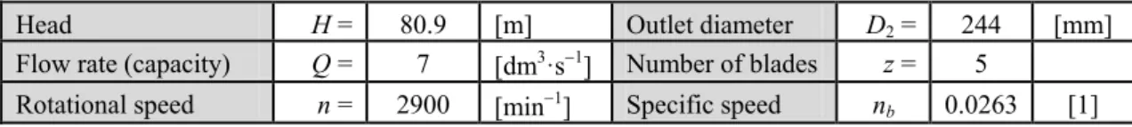
In this study, numerical modelling has been applied to investigate the performance including the leakage flow in a single-stage centrifugal pump with horizontally mounted shaft and twisted blade. The design parameters are specified in table 1.
Tab. 1 Design parameters of modelled centrifugal pump.
Head H = 80.9 [m] Outlet diameter D2 = 244 [mm]
Flow rate (capacity) Q = 7 [dm3·s1] Number of blades z = 5
Rotational speed n = 2900 [min1] Specific speed nb 0.0263 [1]
These parameters yield a very low value of non-dimensional specific speed
80.9 9.81
0.0263,007 . 0 60
2900
75 . 0 5 . 0
75 . 0
5 . 0
b
Y Q n
n (1)
where:
nb– specific speed [1], n– rotational speed [s1], QV – flow rate [m3s1], Y– specific energy [Jkg1]
This value of nb is below the specific speed range commonly considered for the radial type of
impeller. It is caused by the high value of the head in connection with the low value of the flow rate. Such parameters can be reached by twisting the blades of the impeller, as was designed at the Victor Kaplan Department of Fluid Engineering, Energy Institute, Technical University of Brno.
2 NUMERICAL MODELLING OF THE FLOW IN CENTRIFUGAL PUMP
At the beginning of the simulation a 3-dimensional geometric model of the pump components was created which describes the calculation domain by coordinates. This calculation domain was then subdivided into a large number of cells, i.e. a grid is generated, the quality of which is essential for the reliable numerical solution.
2.1 Definition of the computational geometry
Dimensions of hydraulic parts were obtained from the Victor Kaplan Department of Fluid Engineering. Complete technical documentation was provided by Sigma Group Lutín. Based on the drawings, complex geometry of the rotor and stator was defined, including the space between the impeller and casing. The model is presented in Fig.1.
Fig. 1 Computational geometry of the pump.
shroud under the annular seal). Unstructured mesh was generated; the number of cells was about 4300000.
2.2 Numerical modelling
ANSYS FLUENT release 13[1] was applied for numerical modelling of the flow through the pump. The incompressible, isothermal, turbulent flow was modelled in complex 3D geometry. The problem involves multiple moving parts as well as stationary surfaces. Multiple Reference Frame model (MRF) was applied to model such case. MRF approach is steady-state approximations and differs primarily in the manner in which conditions at the interfaces are treated. In this case unsteady problem is transferred to the role of stationary due to the rotating coordinate system. Acceleration of the liquid is incorporated into the model as a new term in the momentum equation. This approach does not allow solving the interaction between the stator and rotor; results are given for one position of blades of the impeller against volute. Simulations take less of a time but dynamic effects of flow are neglected.
Turbulent model k- SST was applied that is recommended for the flow in rotating geometries [3]. This model employs the k- model in the core flow, the k- model near wall and it modifies the relation for the eddy viscosity.
Definition of boundary conditions is illustrated on the Fig. 2.
Fig. 2 Definition of boundary conditions
The convergence of the steady solution can be observed by evaluation of residuals and also by the monitoring of the static pressure at the outlet.
2.3 Losses in hydrodynamic pump
Losses resulting from the transformation of mechanical energy into hydraulic energy can be expressed in the steady state as a power loss:
PvPPu (2)where:
Pvis the sum of all losses, P is the power supplied at the pump shaft, Pu is the usefulpower transferred to fluid PugHQ .
The power dissipation in the pump is converted to heat dissipation.
Fig. 3 Balance of the power flow[3]
In the scheme (Fig.3) the following sources of loss are considered [3]:
Pm–mechanical losses in the bearings and shaft seals. These losses usually do not lead to heating of the liquids and are determined as external loss.
Per–friction losses created by the components of axial thrust balance devices (balance piston or disk).
Ps3 – throttling losses which occur in the annular seal separating two pump stages. These leakages do not flow through the impeller and so they consume only a part of the power; they are evaluated with only about 40% of the head.
PRR–disk friction losses which are generated on rear and front shrouds of the impellers.
PL–volumetric lossesconnected with the leakages.
Volumetric losses belong to secondary losses. Generally they include: the leakage (Qsp) through the annular seal at the impeller inlet
the leakage (QE) through the device for axial thrust balancing
additional amount of fluid (Qh) which may be circulated within the pump for auxiliary
purposes such as sealing or cooling, or feeding a hydrostatic bearing.
To pump all of these leakages, the power PL must be supplied by the impeller where ηv is the
volumetric efficiency.
sp E h
th vth
L g H Q Q Q g H Q
P / (3)
where: h th H H (4)
The volumetric losses can be expressed by means of volumetric efficiency:
Q Q Q Q Q Q Q Q Q Q Q P E S P E S v 1 1 (5)
PVh –hydraulic losses due to friction and turbulent dissipation in all components between suction and discharge nozzle are covered by the hydraulic efficiency ηh. The dissipated power
due to hydraulic losses is then defined:
1 1
h Vh g H Q
P
PRec– lossesdue to fluid recirculationin case of part load. They should be zero near and above the best efficiency point.They cause the greatest part of the power consumption, when operating against a closed valve or at a low flow rate.
All types of losses can be estimated by the help of empirical formulas, but uncertainties of ±20 % to 30 % can be expected. Loss analysis is very important for the pump design as well as for control of the pump performance. Numerical modelling can be a very useful tool for this purpose. In this paper volumetric losses will be investigated connected with the leakage Qsp through the annular
seal at the impeller inlet.
2.4 Leakage through the annular seal
The straight plain annular seal with constant clearance was assumed. For the leakage calculation, the pressure difference across the seal must be defined. This pressure difference depends both on the pump head and the pressure generated by the friction force in a gap between the stator and rotating disks. The distribution of static pressure is illustrated in Fig. 3.
Fig. 3 Contours of static pressure in the impeller and gaps between impeller and rotor.
Fig. 4 Scheme of the leakage losses through annular seals at the suction side of the pump [5].
2
1 2 2 2 2 2 2 1 8 2 1 T h
T r r
u Y Y
p
(7)
The velocity in a gap between the sealing rings:
T
T
p
c 1
1 2 (8)
where is the discharge coefficient defined by:
5 . 1 2 1 l (9)
where: [1] is a friction coefficient dependent on the shape of the sealing ring, [m] is the clearance between the rings,
l [m] is the length of the length of the sealing gap.
Friction coefficient is determined experimentally and for smooth annular seals and turbulent flow its value is in the range = (0.035 - 0.05).
The leakage flow through the annular seal can be calculated from:
T T
sp r c
Q 21 1 (10)
This theoretical prediction can be applied in the case of best efficiency point. Besides the pump optimal operational conditions, numerical modelling can be applied to investigate leakage flow. In this case leakage flow has been investigated for the flow rate ranging from 0 dm3s1 to 10 dm3s1. The results obtained from theoretical prediction and numerical simulation is compared in Fig. 5.
Fig. 5 Comparison of results obtained from theoretical prediction and numerical simulation.
Comparison of results from the theory and numerical modelling shows that for the preliminary estimation of annular seal leakage a simple calculation based on empirical relations can be applied. However, if we want to determine leakage depending on the pump flow rate, it is possible to use numerical modelling tools. This can be of great benefit especially in the stage of pump design, when the shape, clearance and other important features of the annular seal can be tested. In this modelled case the annular seal leakage substantially exceeds volume loss specified in the literature (about 3% - 5% of rated flow). In this case it would be useful to use the labyrinth or different type of grooves in order to increase the flow resistance.
3 CONCLUSIONS
It can be concluded, that the annular seal leakage can be predicted by empirical formulas derived from measurements. For the investigation of the annular seal leakage in dependence on the pump flow rate, numerical modelling can be applied. Numerical modelling can provide deeper insight into fluid flow in a centrifugal pump. Close interaction exists between leakage flow, pressure distribution in the impeller sidewall gap, disk friction and main flow. The results obtained with numerical modelling can lead to change of the seal type or modification of its geometry. Numerical investigation carried out for alternative shape of the annular seal can help to evaluate whether the change in geometry is reflected in the pump parameters.
REFERENCES
[1] FLUENT 6.3.26 –User´s guide. Fluent Inc. 2003 [online]. Datum poslední revize 3.10.2006 [cit. 2008-12-08]. Dostupné z
< http://spc.vsb.cz/portal/cz/documentation/manual/doc.vsb.cz/Aplikacni%20software/FlueFl_ 6.3.26/pdf/ug/flug.pdf >.
[2] BLAHA, J.; BRADA, K. Hydraulické stroje. 1st ed. Praha: SNTL, 1992. 747 pp. ISBN 80-03-00665-1.
[3] GÜLICH, JOHANN, F. Centrifugal Pumps, Second Edition: Springer, 2010. 964 pp. ISBN 978-3-642-12823-3.
[4] TUZSON, J. Centrifugal pump design 2000. 320 pp. ISBN 0-471-36100-3.
[5] PACIGA, A., STRÝČEK, O., GANČO, M. Čerpacia technika. Praha: SNTL, 1984. 224 s.

![Fig. 3 Balance of the power flow [3]](https://thumb-eu.123doks.com/thumbv2/123dok_br/18451588.364284/4.892.288.609.79.309/fig-balance-power-flow.webp)

![Fig. 4 Scheme of the leakage losses through annular seals at the suction side of the pump [5]](https://thumb-eu.123doks.com/thumbv2/123dok_br/18451588.364284/6.892.305.584.69.321/fig-scheme-leakage-losses-annular-seals-suction-pump.webp)

