An isotropic damage model to simulate collapse
in reinforced concrete elements
1 INTRODUCTION
The simulation of structures in their evolution to collapse is an interesting topic in engineering to know the remaining capacity of a structure after reaching the ultimate load, which is dependent on the constitutive behaviour of their construction materials. After concrete reaches its ultimate load, it presents a reduction of its load-carrying capacity, so the stresses decreases while the strains in-creases; this behaviour is typically called strains softening.
The continuum damage mechanics can be used for modelling concrete failure, one of the pioneers of damage mechanics theory was Kachanov (1958), who introduced the fundamental concepts of the continuous damage mechanics, i.e., effective strain, effective stress and scalar damage variable. There are many local damage models based on the damage framework such as: isotropic damage models (Kachanov 1958, Krajcinovic 1984, 1985, Lemaitre 1986, Simo and Ju 1987a, Lubliner et al.
1989, Mazars and Pijaudier-Cabot 1989, Lubarda et al. 1994, Faria et al. 1998, Lee and Fenves Juárez-Luna G.a,*
Méndez-Martínez H.a,1 Ruiz-Sandoval M.E.a,2
a Universidad Autónoma Metropolita-na, San Pablo No. 180, Col. Reynosa Tamaulipas, 02200 México, D.F. Telephone: (55) 5318-9085; Fax: (55)5318-9085;
* [email protected], 1 [email protected], 2 [email protected]
Received 22.01.2014 In revised form 16.05.2014 Accepted 03.06.2014 Available online 17.08.2014
Abstract
A damage model with different failure surface in tension and compression is formulated, implemented and validated to study reinforced concrete elements under actions which induce their collapse. The constitutive behaviour of concrete considers the softening deformation after reaching a failure surface, whereas the hardening of the reinforcing steel is represented by a plasticity von Mises surface. The developed damage model does not exhibit the problem of stress locking as the smeared cracking model does; this guaranties an adequate energy release as the material fails. Numerical examples are presented showing the validity of the developed damage model for modelling the behaviour of rein-forced concrete elements up to their collapse.
Keywords
Latin American Journal of Solids and Structures 11 (2014) 2444-2459
1998, Comi 2001, Jason et al. 2006, Contrafatto and Cuomo 2006, Wu et al. 2006 and Gopinath et al. 2012); anisotropic damage models (Dragon and Mroz 1979, Cordebois and Sidoroff 1979, Krajci-novic and Fonseka 1981, Ortiz 1985, Simo and Ju 1987a, b, Ju 1989, 1990, Voyiadjis and Abu-Lebdeh 1994, Govindjee et al. 1995, Halm and Dragon 1996, Fichant et al. 1999, Lemaitre et al. 2000, Carol et al. 2001 and Cicekli et al. 2007).
It is well kwon that local continuum damage models lead to a physically unrealistic description of the strain localization phenomenon. When the tangent stiffness matrix is not positive definite, the governing differential equations may lose ellipticity, which renders the boundary value problem ill posed (Needleman 1988, Jirásek 1998). In finite elements computations spurious mesh sensitivity problems occur, strain localizes into a narrow band whose width depends on the element size, the corresponding load-displacement curve always shows snapback for a fine mesh and the dissipate fracture energy converges to zero. To overcome the shortcomings of local theories for modelling strain softening, some alternatives have been proposed such as: non-local modelling of the constitu-tive behaviour (Costa Mattos et al. 1992, Costa Mattos and Sampaio 1995, Da Costa Mattos et al.
2009), gradient material description (Triantafylidis and Aifantis 1986, Peerlings et al. 1996), mi-cropolar continuum theory (de Borst 1991, Steinmann 1995), viscous regularization (de Borst and Mühlhaus 1992) and local manipulations of the material properties depending on the element size (Bazant and Oh 1983, Crisfield 1986, Oliver 1989). Recently, Da Costa-Mattos et al. (2009) pro-posed a special gradient-enhanced damage theory in which the material is considered to possess a substructure or microstructure, where the free energy is supposed to depend not only on the strain and the damage variable but also on the damage gradient.
If the concrete is modelled with the finite element method and local damage models, the damage of a cracking surface is distributed into the material volume of a finite element, which is incon-sistent with the fracture energy dissipated per unit of area and per unit of volume. This disagree-ment is overcome with a characteristic length such as the proposed one by Bazant and Oh (1983), who used a thickness of the cracking band, depending on the element area and on the propagation direction; Crisfield (1986) proposed a characteristic length defined by the Jacobian in each integra-tion point; and Oliver (1989) developed a general method for computing the characteristic length depending on the element size and the elastic stress state.
The Software Ansys 12.0 uses a damage surface for concrete with different threshold values un-der tension and compression, coherent with the behaviour reported in laboratory test such as Kup-fer and Gerstle (1973). However, this model has as a drawback that fracture energy has a fixed value, which is not possible to modify, so the results are dependent on that fixed energy fracture. Also, Ansys only considers linear softening curve, even though there are other curves with a better approximation such as bilinear, trilinear and exponential. Alternatively, the Software Diana 9.0 uses the smear cracking model for concrete (Rashid 1968, Rots 1988), in which is possible to assign the value of the fracture energy density. Nevertheless, this model has problems of mesh dependency, stress locking and spurious kinematic modes.
materi-Latin American Journal of Solids and Structures 11 (2014) 2444-2459
al failure is the strain localization model (Simo et al. 1993, Oliver 1996a, 1996b, Armero and Garikipati 1996, Juárez and Ayala 2009, Juárez-Luna and Ayala 2014), which considers that only one discontinuity (crack) may propagate into a finite element, so in the case that multi cracks ap-pears, the computational cost of their propagation is high.
For the aforementioned reasons, this paper promotes the use of continuous damage models, which do not need computational costly tracking algorithms. A continuous damage model is devel-oped and implemented to simulate the constitutive behaviour of the concrete in its evolution to collapse. This damage model, called different tension-compression (DTC), has a failure surface with the corresponding threshold values in tension and compression of the concrete. Additionally, in this model, it is possible to assign the density energy magnitude and it does not have the problems re-ported by Rots (1988).
The proposed DTC damage model uses the failure surface proposed by Oliver et al. (1990). Nev-ertheless, the tangent constitutive tensor is different to the one developed by Linero (2006). The DTC damage model was implemented into the subroutines of the Finite Element Analysis Program (FEAP) (Taylor 2008), then it was validated with the numerical reproduction of numerical exam-ples and experimental reinforce concrete tests reported in the literature. It is important to mention that in this paper, the material failure is represented by a isotropic damage variable, which repre-sents the degradation level, so the material degradation into the finite element analyses is presented as localization zones where important displacements occurs, but not as physical discontinuities (cracks).
2 DAMAGE MODEL FORMULATIONS
2.1 Equal tension-compression
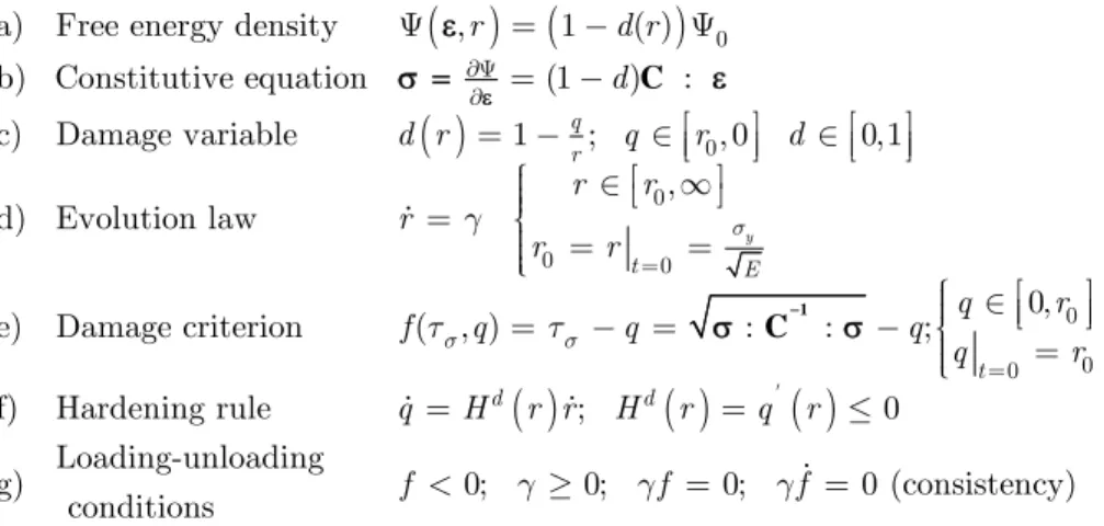
The isotropic continuum damage model by Simo and Ju (1987a) and Oliver et al. (2002) with a failure surface equal tension-compression (ETC) is shown in
Figure 1 for 1D and 2D problems, where the ultimate tensile and compressive strength, ut, and, uc,
respectively, have the same magnitude. This model, typically used to simulate the constitutive be-haviour of some metals, is defined by the following equations:
( ) (
)
( )
C 0 0 0 0 0a) Free energy density , 1 ( )
b) Constitutive equation (1 ) :
c) Damage variable 1 ; , 0 0,1
, d) Evolution law
e) Damage criterion ( , )
y
q r
t E
r d r
d
d r q r d
r r
r
r r
f q q
s s s g t t ¶Y ¶ =
Y = - Y
=
-é ù é ù
= - Îêë úû Îêë úû
ì é ù
ï Î ë ¥û
ïï
= íï =
= ïïî = - =
( )
( )
( )
1 C 0 0 0 0, : : ;f) Hardening rule ; 0
Loading-unloading
g) 0; 0; 0; 0 (consistency)
conditions t d d q r q q r
q H r r H r q r
f g gf gf
¢ =
ì é ù
ï Î ï êë úû
- íïïî =
= = £
< ³ = =
Latin American Journal of Solids and Structures 11 (2014) 2444-2459
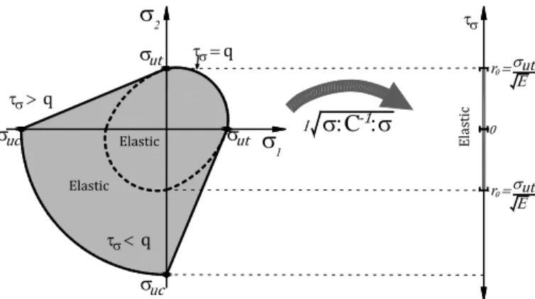
where Ψ is the free energy density, ε is the strain tensor, σ is the stress tensor and C is the elastic tensor. The damage variable, d, is defined in terms of hardening/softening variable q, which is de-pendent on the hardening/softening parameter, H. The damage multiplier γ determine the loading-unloading condition, the function, f( ,q), bounds the elastic domain defining the damage surface in the stress space. The value, ro, is the threshold that determines the limit of the initial elastic
do-main, i.e, q=ro. In this ETC damage surface, any stress state is transformed to a norm, bounded by ro, where every stress state outside of this circle is inelastic as shown in
Figure 2.
1
2
ut
Elastic
q
q
q
ut uc
uc ut
uc
a b
Figure 1: ITC model: a) 1D behaviour and b) 2D failure surface.
2 q
q
q
Elastic
ut
ut
uc Elas
tic
1
C
Elastic
r
ut
‐
r
ut
Figure 2: Transformation of the stress state to a norm.
The tangent constitutive equation, in terms of rates, from the model in Eq. (1) is:
:
T
C (2)
Where CT is the continuum tangent constitutive operator, relating the stress and the strains rates,
of the nonlinear loading interval, which is defined by
3
(1 ) ( : : )
T q Hr
d
r
-= - - Ä
Latin American Journal of Solids and Structures 11 (2014) 2444-2459
and for the elastic loading and unloading interval(
d
0
):(
)
CT 1-d C (4)
2.2 Different tension-compression
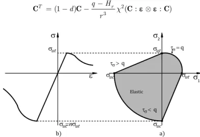
The formulation of the damage model with failure surface DTC is based on the ETC damage mod-el. The main difference of this model is the definition of the norm, which is modified for a parame-ter proposed by Lubliner et al. (1989). It is well known that concrete has a ratio between the com-pression and tension strength of 10 to 20, i.e., n= uc/ ut, as shown in Figure 3. To have a failure
surface with that characteristic, the norm given in Eq. (1)e, is modified by the parameter χ, then
1
C
( , ) : :
f ts q =cts - =q c -r (5)
Also, the tangent constitutive tensor, CT, for the nonlinear interval is:
2 3
(1 ) ( : : )
T q Hr
d
r c
-= - - Ä
C C C C (6)
1 2
q
q
q
Elastic
ut
ut
uc
uc
ut
=n
uc ut
Figure 3: Constitutive behaviour of plain concrete: a) 1D and b) 2D
The parameter
in Eqs. (5)1
( )
n f
c= +f - (7)
Latin American Journal of Solids and Structures 11 (2014) 2444-2459 3 1 3 1 i i i i s f s = = =
å
å
(8)Where the Maclauy operator and the symbol || consider, respectively, the positive and the abso-lute magnitudes of the principal stresses. The interval of ϕ is [0,1], bounded by 0 for a triaxial com-pression ( 3 ≤ 2 ≤ 1 ≤0) and 1 for triaxial tension (0 ≤ 3≤ 2 ≤ 1). Consequently, the corresponding
interval of χ is [1/n,1], bounded by 1/n for a triaxial compresion and 1 for triaxial tension.
The parameter χ scales down 1/n times the norm, as shown in Figure 4, in such a way it is com-pared with the elastic interval [0,ro]. The value of ro= ut/ depends on the threshold value of ut
and the Young's modulus E. Note that the initial elastic interval is the same for 1D, 2D and 3D problems, all with a limit point ro, and that for a 2D principal stress state, the parameter χ takes
the value of 1 in the firts quadrant, 1/n in the third quadrant and the interval [1/n,1] in the second and fourth quadrants.
The algorithm to implement the DTC damage model is as follows:
1. Initial data
Material properties: n, Gf, ut,
Current values: εt+1, dt+1, rt+1
2. Evaluate the effective stresses and norm
1 1
1 1 1
:
: :
t t
t t t
t c + + + + + = = 1 C C
(9)
3. Identification of state (if t=0, then
r
0
ut/
E
): a) If t+1 <rt, the elastic/unload/neutral load case, then(
)
C C
1
1
1 1
1 1 1
( ) 1 1 (1 ) t t t t t T t t
t t t
Latin American Journal of Solids and Structures 11 (2014) 2444-2459
b) If t+1>rt, the load case, then
(
)
(
)
1 1 1 1 1 1 21 1 3 1 1
1
1 1 1
( ) 1 1 (1 ) t t t t t t T
t t t t
t
t t t
r q r d r q Hr d r d t c + + + + + + + + + + + + + + = = -=
-C C
(11)
4. Output values: rt, CT and t+1.
2 q
q
q
Elastic
ut
ut
uc Elastic 1
C
‐ El as tic r ut r ut
Figure 4: Transformation of the stresses to a norm.
Note that if the value of χ=1 in the norm and in the tangent constitutive tensor, the ETC continu-ous damage model is recovered. An equivalent way of evaluate the damage criterion is proposed, modifying the threshold value of ro in the limit point for the value of rom=ro/χ. With this
modifica-tion, in a 2D principal stress state, the value of ro is scaled up 1 time in the first quadrant, n times
in the third quadrant and 1 to n times in the second and fourth quadrants, as shown in Figure 5. Then, the algorithm for the ETC continuous damage needs only a modification in the threshold value of ro. Both ways of the DTC continuous damage model were implemented in the user routines
Latin American Journal of Solids and Structures 11 (2014) 2444-2459
2
q
q
q
Elastic
ut
ut
uc Elastic 1
C
r mut
‐
El
as
tic
r mut
Figure 5: Transformation of the stresses to a norm with a modified r0.
3 NUMERICAL EXAMPLES
In the three presented examples, the reinforcement was meshed with 3D linear elements with two nodes equipped with three degrees of freedom. The constitutive behaviour of the steel reinforcement was modelled with a plasticity surface of von Mises. The steel elements were placed on the bounda-ry of the solid elements, coupling the degree of freedom of both kinds of elements and then perfect bond was considered. This DTC damage model was validated for plain concrete elements in Mén-dez-Martínez and Juárez-Luna (2012).
3.1 Lightly reinforced concrete beam
In this example, a simple supported concrete beam is analysed, the dimensions of the reinforcement and boundary conditions are shown in Figure 6. A load is applied at the centre of the span by dis-placement control, which is gradually imposed downwards. The mechanical properties of the con-crete are: Young's modulus, Ec=24132 MPa, Poisson ratio ν=0.2, ultimate tensile strength com-pressive tu=2.41 MPa, ultimate compressive strength cu=33.23 MPa and fracture energy density
Gf=0.263 N/mm. The mechanical properties of the steel reinforcement are: Young's modulus,
Es=203.4 GPa, yield stress y=324 MPa, Poisson ratio ν=0.3, area A=5.07 cm2, hardening modulus H=6.9 GPa and strain at which tensile strength is achieved 10%.
P
182.88
Measuring in cm
182.88 365.76
20.32
50
.8
5.08 10.16 5.08
( )2#8
Axis of symmetry Axis of symmetry
Latin American Journal of Solids and Structures 11 (2014) 2444-2459
The beam was meshed with hexahedral elements as shown in Figure 7a, where only a quarter of the beam was modelled because of its symmetry, reducing the time consuming of the computational cost. As can be seen, the failure started into the finite elements placed around the centre on the span, at the bottom of the beam as shown in Figure 7b, which is coherent with the experimental results reported by Burns and Seiss (1962). The load vs. displacement curves at the centre of the span are shown in Figure 8, where the curve computed with the DTC damage model is acceptable with the curve reported by Burns and Seiss (1962), showing the validity of the implemented DTC damage model to simulate reinforced concrete elements.
(a) (b)
Figure 7: Mesh: a) undeformed and b) deformed
DTC
Burns and Seiss (1962)
0 0.005 0.010 0.015
u (m)
20
P
(
k
N)
180
0 40 60 80 100 120 140 160
Figure 8: Load vs. displacement curves.
3.2 Reinforced concrete circular slab
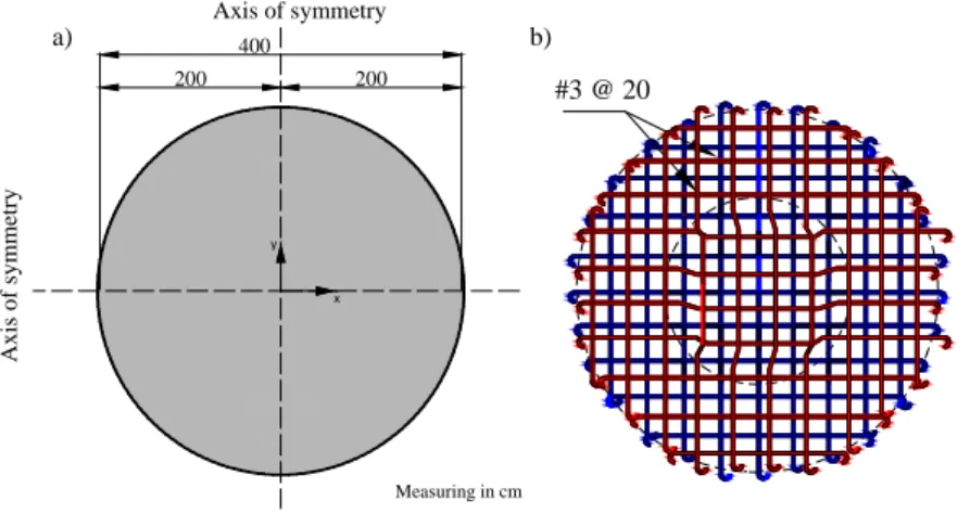
In this example, a reinforced concrete slab with circular shape was studied, in which a distributed uniform load is gradually applied downwards. Two boundary conditions were considered at the border of the slab, simple supported and fixed. The geometry and reinforcement of the slab with thickness of 0.10 m are shown in
Figure 9. The mechanical properties of the concrete are: Young's modulus Ec=14710 MPa, Poisson
ratio ν=0.2, ultimate tensile strength tu=2.45 MPa, ultimate compressive strength cu=29.42 M Pa
fracture energy density Gf=0.098 N/mm. The mechanical properties of the steel reinforcement are:
Young's modulus Es=196.13 MPa, yield stress y=411.88 MPa, Poisson ratio ν=0.3, area A=0.71 cm2and hardening modulus H=2.871 GPa.
Axis of symmetry Axis of
Latin American Journal of Solids and Structures 11 (2014) 2444-2459
x y
Axis of symmetry
Ax
is o
f symmetry
400
200 200
Measuring in cm
#3 @ 20
a) b)
Figure 9: Circular slab: a) geometry and b) reinforcement.
As the previous example, the two axes or symmetry were considered, so only a quarter of the slab was modelled with hexahedral elements, as shown in Figure 10a, to reduce the time consuming of the computational calculation. The undeformed meshes are shown in Figure 10b and c, for the sim-ple supported and fixed at the border of the slab, respectively.
The load vs. displacements curves are shown in Figure 11a and b for simple supported and fixed conditions, respectively. These curves are compared with those reported by Caballero (2012), com-puted by a smear crack model in the Software ANSYS. As can be seen, both comcom-puted curves are coherent with those simulated with a smear crack model.
(a) (b) (c)
Figure 10: Mesh: a) circular slab, b) simple supported and c) fixed.
DTC
Caballero-Garatachea (2011)
0 0.01 0.05
u (m)
P
(
k
N)
20
0 5
0.02 0.03 0.04 10
15
DTC
Caballero-Garatachea (2011)
0 0.01 0.05
u (m)
P
(
k
N)
120
0 20
0.02 0.03 0.04 40
60 80 100
a) b)
Latin American Journal of Solids and Structures 11 (2014) 2444-2459
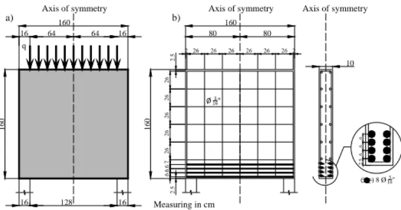
3.3 Reinforced concrete deep beam
In this example, a reinforced concreted deep beam (l/h=1) is analysed, where a distributed uniformed load, with magnitude q=0.0078125P, is gradually applied downwards on the top of the beam shown in Figure 12a. The me-chanical properties of the concrete are: Young's modulus Ec=31400 MPa, Poisson ratio ν=0.2, ultimate tensile
strength tu=2.5 MPa, ultimate compressive strength tu=29.63 MPa and fracture energy density Gf=0.098 N/mm.
The mechanical properties of the steel reinforcement are: Young's modulus Es=206 GPa, yield stress y=536.6 MPa,
Poisson ratio ν=0.3, area of the principal reinforcement bars A1=0.503 cm2 and the secondary reinforcement bars
A2=0.178 cm2 and hardening modulus H=2.871 GPa. The distribution of the reinforcement is shown in Figure 12b.
160
16
0
Axis of symmetry
Measuring in cm
160
16
0
Axis of symmetry
80 80
2 26 26 26 26 26 262
2.
5
6
6
6
7
26
26
26
26
26
2.
5
2.
5
6
6
6
10
Axis of symmetry
( ) 8 Ø 5 16" Ø 3
16"
b)
16 64 64 16
16 128 16
q
a)
Figure 12: Deep beam: a) geometry and b) reinforcement.
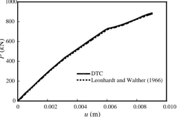
In this example, an elastoplastic constitutive model was assigned to the steel as Leonhardt and Walther (1966) did. Taking advantage of the symmetry, only a quarter of the beam was modelled to reduce the time consuming computational cost. Figure 13 shows the 3D mesh, discretized with hexahedral elements.
(a) (b)
Figure 13: Mesh: a) undeformed and b) deformed.
Latin American Journal of Solids and Structures 11 (2014) 2444-2459
DTC
Leonhardt and Walther (1966)
0 0.002 0.010
u (m)
P
(
k
N)
1000
0
0.004 0.006 0.008 200
400 600 800
Figure 14: Load vs. displacement curves.
4 CONCLUSIONS
A damage model to simulate concrete elements to collapse was developed, implemented and vali-dated, based on the damage mechanics continuous theory. The damage model considers a constitu-tive behaviour equipped with softening for the concrete elements limited for a damage surface, whereas for the reinforced concreted elements, a plasticity model was assigned to the reinforcement, which take into account the hardening of the steel with a Von Mises surface.
A DTC damage surface for concrete is obtained by scaling down the norm and the tangent modulus with the parameter χ, but it is equivalent by scaling up the threshold value of ro. In both
cases, the integration algorithm of the ETC damage model needs two and one modification, respec-tively, to have a surface with different threshold values in tension and compression.
The global behaviour of reinforced concrete elements is controlled by the hardening of the rein-forcement steel. Their simulation with damage models for concrete and plasticity model for the steel provides the cracking zones, the crack paths and the ultimate load of the specimen.
The numerical results computed with the DTC damage model are coherent with the experi-mental and numerical results reported in the scientific literature, since it properly simulates the strain softening of the concrete and localizes the degradation zones.
To consider perfect bond between steel reinforcement and concrete does not show evident effects in the presented numerical examples.
It is useful over some commercial software that it is possible to assign the fracture energy densi-ty value in the implemented damage model, because the numerical results are dependent on this value.
Latin American Journal of Solids and Structures 11 (2014) 2444-2459 Acknowledgements
The authors acknowledge the support given by the Universidad Autonoma Metropolitana. The first author acknowledges the financial support by CONACYT under the agreement number I010/176/2012 with the Universidad Autónoma Metropolitana, in the context of the research pro-ject: “Analysis and design of concrete slabs”. The second author acknowledges the scholarship for his Master given by CONACYT.
References
ANSYS, (2009). Ansys 12.0.1. Ansys Inc. USA.
Armero, F., Garikipati, K. (1996). An analysis of strong discontinuities in multiplicative finite strain plasticity and their relation with the numerical simulation of strain localization in solids, International Journal of Solids and Struc-tures 33(20): 2863-2885.
Bazant, Z., Oh, B.H. (1983). Crack band theory for fracture of concrete, Materials and Structures 16(3): 155-177. Burns, N.H., Seiss, C.P. (1962). Load-deformation characteristics of beam-column connections in reinforced concrete, Technical Report Civil Engineering Studies SRS-234, Civil Engineering Department, University of Illinois at Urbana-Champaign, USA.
Caballero, O. (2012). Determinación de coeficientes de diseño y trayectorias de agrietamiento de losas circulares, elípticas y triangulares en condición aislada, Master thesis, Universidad Autónoma Metropolitana, Azcapotzalco, Mexico. (In Spanish).
Carol, I., Rizzi, E., William, K.J. (2001). On the Formulation of anisotropic elastic degradation. I. Generalized pseu-do-Rankine model for tensile damage, International Journal of Solids and Structures 38(4): 519-546.
Cicekli, U., Voyiadjis, G.Z., Abu Al-Rub, R.K. (2007). A plasticity and anisotropic damage model for plain concrete, International Journal of Plasticity 23(10-11): 1874-1900.
Comi, C. (2001). A non-local model with tension and compression damage mechanisms, European Journal of Me-chanics - A/Solids 20(1) 1-22.
Contrafatto, L., Cuomo, M. (2006). A framework of elastic-plastic damaging model for concrete under multiaxial stress states - International Journal of Plasticity, 22(12): 2272-2300.
Cordebois, J.P., Sidoroff, F. (1979). Anisotropic damage in elasticity and plasticity, Journal de Mecanique Theo-rique et Applilquee, Special number, 45-40.
Costa Mattos, H., Fremond, M., Mamiya, E. N. (1992). A simple model of the mechanical behavior of ceramic-like materials, International Journal of Solids and Structures 29(24): 3185–3200.
Costa Mattos, H.S., Sampaio R. (1995). Analysis of the fracture of brittle elastic materials using a continuum dam-age model, Structural Engineering and Mechanics 3(5): 411–427.
Crisfield, M.A. (1986). Snap-through and snap-back response in concrete structures and the dangers of under inte-gration, International Journal for Numerical Methods in Engineering 22(3): 751-756.
Latin American Journal of Solids and Structures 11 (2014) 2444-2459 de Borst, R. (1991). Simulation of strain localization: a reappraisal of the Cosserat continuum, Engineering Compu-tations 8(4): 317-332.
de Borst, R., Mühlhaus, H.B. (1992). Gradient-dependent plasticity: formulation and algorithmic aspects, Interna-tional Journal for Numerical Methods in Engineering 35(3): 521-539.
DIANA (2008), DIANA 9.0: Finite Element Analysis User's Manual Release. TNO DIANA BV, Delft, The Nether-lands.
Dragon, A., Mroz, Z. (1979). A continuum model for plastic-brittle behavior of rock and concrete, International Journal of Engineering Science 17(2): 121-137.
Faria, A., Oliver, J., Cervera, M. (1998). A strain-based plastic viscous-damage model for massive concrete struc-tures, International Journal of Solids and Structures 35(14): 1533-1558.
Fichant, S., Borderie, C.L., Pijaudier-Cabot, G. (1999). Isotropic and anisotropic descriptions of damage in concrete structures, Mechanics of Cohesive-frictional Materials 4(4): 339-359.
Gopinath, S., Rajasankar, J., Iyer, N.R. (2012). Nonlinear analysis of RC structures using isotropic damage model, International Journal of Damage Mechanics 21(5): 647-669.
Govindjee, S., Kay, G.J., Simo, J.C. (1995). Anisotropic modelling and numerical simulation of brittle damage in concrete, International Journal for Numerical Methods in Engineering 38(21): 3611-3633.
Halm, D., Dragon, A. (1996). A model of anisotropic damage by mesocrack growth; unilateral effect, International Journal of Damage Mechanics 5(4): 384-402.
Hillerborg, A., Modeer, M., Petersson, P.E. (1976). Analysis of crack formation and crack growth in concrete by means of fracture mechanics and finite elements, Cement and Concrete Research 6(6): 773-782.
Jason, L., Huerta, A., Pijaudier-Cabot, G., Ghavamian, S. (2006). An elastic plastic damage formulation for con-crete: Application to elementary tests and comparison with an isotropic damage model, Computer Methods in Ap-plied Mechanics and Engineering 195(52): 7077-7092.
Jirásek, M. (1998). Nonlocal models for damage and fracture: Comparison of approaches, 35(31–32): 4133–4145. Ju, J.W. (1989). On energy-based coupled elasto-plastic damage theories, constitutive modeling and computational aspects, International Journal of Solids and Structures 25(7): 803-833.
Ju, J.W. (1990). Isotropic and anisotropic damage variables in continuum damage mechanics, ASCE Journal of Engineering Mechanics 116(12): 2764-2770.
Juárez, G., Ayala, G.A. (2009). Variational formulation of the material failure process in solids by embedded discon-tinuities model, Numerical Methods for Partial Differential Equations 25(1): 26-62.
Juárez-Luna, G., Ayala, G.A. (2014). Improvement of some features of finite elements with embedded discontinuities, Engineering Fracture Mechanics 118: 31-48.
Kachonov, L.M. (1958). On the creep fracture time, Izv. Akad. Nauk USSR Otd. Tech. 8: 26-31. (in Russian). Krajcinovic, D. (1984). Continuum damage mechanics, Applied Mechanics Reviews 37(1): 1-6.
Krajcinovic, D. (1985). Continuous damage mechanics revisited: basic concepts and definitions, Journal of Applied Mechanics 52(4): 829-834.
Latin American Journal of Solids and Structures 11 (2014) 2444-2459
Kupfer, H.B., Gerstle, K.H. (1973). Behavior of concrete under biaxial stresses, ASCE Journal of Engineering Me-chanics 99(4): 853-866.
Lee, J., Fenves, G.L. (1998). Plastic-damage model for cyclic loading of concrete structures, ASCE Journal of Engi-neering Mechanics 124(8): 892-900.
Lemaitre, J. (1986). Local approach to fracture, Engineering Fracture Mechanics 25(56): 523-537.
Lemaitre, J., Demorat, Sauzay, R.M. (2000). Anisotropic damage law of evolution, European Journal of Mechanics - A/Solids 19(2): 513-524.
Leonhardt, F., Walther, R. (1966). Wandartige Trager. Deutscher Ausschuss für Stahlbeton, Berlin, Heft 178. Linero, D.L. (2006). Un modelo del fallo material en el hormigón armado, mediante la metodología de discontinuida-des fuertes de continuo y la teoría de mezclas. Dissertation, Escola Tècnica Superior d'Enginyers de Camins, Canals i Ports, Universidad Politécnica de Cataluña, Spain. (In Spanish).
Lubarda, V.A., Kracjinvovic, D., Mastilovic, S. (1994). Damage model for brittle elastic solids with unequal tensile and compressive strength, Engineering Fracture Mechanics 49(5): 681-697.
Lubliner, J., Oliver, J., Oller, S., Onate, E. (1989). A plastic-damage model for concrete, International Journal of Solids and Structures 25(3): 299-326.
Mazars, J., Pijaudier-Cabot, G., (1989). Continuum damage theory: Application to concrete, ASCE Journal of Engi-neering Mechanics 115(2): 345-365.
Méndez-Martínez H., Juárez-Luna, G. (2012). Implementación de un modelo de daño continuo para la simulación al colapso de estructuras de concreto, Concreto y Cemento. Investigación y Desarrollo, Instituto Mexicano del Cemento y del Concreto A.C., 3(2): 19-33. (In Spanish).
Needleman, A. (1988). Material rate dependence and mesh sensitivity in localization problems, Computer Methods in Applied Mechanics and Engineering 67(1): 69-87.
Oliver, J. (1989). A consistent characteristic length for smeared cracking models, International Journal for Numerical Methods in Engineering 28(2): 461-474.
Oliver, J., Cervera, M., Oller, S., Lubliner, J. (1990). Isotropic damage models and smeared crack analysis of con-crete. In N. B. et al., Eds, SCI-C Computer Aided Analysis and Design of Concrete Structures, Swansea, Pineridge Press, 945-957.
Oliver, J. (1996a). Modelling strong discontinuities in solid mechanics via strain softening constitutive equations, Part 1: Fundamentals, International Journal for Numerical Methods in Engineering 39(21): 3575-3600.
Oliver, J. (1996b). Modelling strong discontinuities in solid mechanics via strain softening constitutive equations. Part 2: Numerical simulation, International Journal for Numerical Methods in Engineering 39(21): 3601-3623. Oliver, J., Huespe, A.E., Pulido, M.D.G., Chaves, E. (2002). From continuum mechanics to fracture mechanics: the strong discontinuity approach, Engineering Fracture Mechanics 69(2): 113-136.
Ortiz, M. (1985). A constitutive theory for the inelastic behavior of concrete, Mechanics of Materials 4(1): 67-93. Peerlings, R.H.J., De Borst, R., Brekelmans, W.A.M., De Vree J.H.P. (1996). Gradient enhanced damage for quasi-brittle materials, International Journal for Numerical Methods in Engineering 39(19): 3391-3403.
Latin American Journal of Solids and Structures 11 (2014) 2444-2459 Rots, J.G. (1988). Computational modeling of concrete fracture, Dissertation, Delft University of Technology, Delft, Netherlands.
Simo, J.C., Ju, J.W. (1987a). Strain and stress based continuum damage models. I. Formulation, International Jour-nal of Solids and Structures 23(7): 821-840.
Simo, J.C., Ju, J.W. (1987b). Strain- and stress-based continuum damage models. Part II: Computational aspects, International Journal of Solids and Structures 23(7): 841-869.
Simo, J.C., Oliver, J., Armero, F. (1993). An analysis of strong discontinuities induced by strain-softening in rate-independent inelastic solids, Computatlonal Mechanics 12: 277-296.
Steinmann, P. (1995). Theory and numerics of ductile micropolar elastoplastic damage, International Journal for Numerical Methods in Engineering 38(4): 583-606
Taylor, R.L. (2008). A Finite Element Analysis Program, Version 8.2. Department of Civil and Environmental Engi-neering, University of California, Berkeley.
Triantafylidis, N., Aifantis, E. C. (1986). A gradient approach to localization of deformation. I. Hyperelastic materi-als, Journal of Elasticity 16(3): 225-237.
Voyiadjis, G.Z., Abu-Lebdeh, T.M. (1994). Plasticity model for concrete using the bounding surface concept, Inter-national Journal of Plasticity 10(1): 1-21.