Ar
ti
cl
e
0103 - 5053 $6.00+0.00
*e-mail: [email protected]
Development of a Flow through Photo-Reactor to Study Degradation of Organic
Compounds by Sequential Injection Analysis (SIA)
Allan C. V. dos Santos and Jorge C. Masini*
Instituto de Química, Universidade de São Paulo, CP 26077, 05513-970 São Paulo-SP, Brazil
Este trabalho descreve um foto-reator para a execução “in line” da degradação de compostos orgânicos através da reação de foto-Fenton, utilizando-se de um sistema de Análise por Injeção Sequencial (SIA). Uma solução do corante do sal tetrassódico de ácido 3,4′,4″,4″′-tetrassulfônico de ftalocianina de cobre foi empregada como modelo da família das ftalocianinas, cujos pigmentos apresentam grande utilização na indústria de tintas automotivas. Baseando-se em testes preliminares, uma remoção de cor de 97% foi obtida em uma solução contendo 20 µmol L-1 deste corante.
This work describes a photo-reactor to perform in line degradation of organic compounds by photo-Fenton reaction using Sequential Injection Analysis (SIA) system. A copper phthalocyanine-3,4′,4″,4″′-tetrasulfonic acid tetrasodium salt dye solution was used as a model compound for the phthalocyanine family, whose pigments have a large use in automotive coatings industry. Based on preliminary tests, 97% of color removal was obtained from a solution containing 20 µmol L-1
of this dye.
Keywords: photo-Fenton reactor, sequential injection analysis, wastewater, copper phthalocyanine dye, automotive coatings industry.
Introduction
Oxidative destruction of chemicals provides ultimate
solutions for the treatment of hazardous wastes1. Advanced
Oxidative Processes (AOP’s) are based on the generation
of the hydroxyl radical, •OH, a species that acts as a
strong oxidant to a wide variety of organic and inorganic
compounds2. A special kind of AOP is the Fenton reaction,3
in which the hydroxyl radical is formed from the reaction
between H2O2 and Fe(II) ions. This reaction can also be
processed under inluence of ultraviolet radiation, leading to the so-called photo-Fenton reaction. The Fenton and related reactions are viewed as potentially convenient and economical ways to generate oxidizing species for treating chemical wastes; compared to other bulk oxidants, hydrogen peroxide and iron are inexpensive,
safe, and environmentally friendly4. AOP’s are particularly
interesting for non-biodegradable compounds that can be
recalcitrant and/or toxic to microorganisms5.
Flow techniques are being consolidated as powerful tools for the routine control of parameters in various
samples of environmental origin6. Sequential Injection
Analysis (SIA), a low technique proposed by Ruzicka and
Marshall, 7 can be used to perform experiments necessary
for the optimization of industrial processes8. The purpose
of this paper is to describe an UV reactor speciically designed to study photo-Fenton reactions with a SIA system. A solution of copper phthalocyanine dye was used as a model compound for the phthalocyanine family, whose pigments may be present in efluents of automotive coatings industry.
Experimental
Reagents
All reagents were of analytical grade and the working solutions were prepared in deionized water obtained from a Simplicity 185 system from Millipore coupled to an UV lamp (Millipore, São Paulo, SP, Brazil).
Copper phthalocyanine dye, specifically copper
phthalocyanine-3,4′,4″,4″′-tetrasulfonic acid tetrasodium
salt, molecular formula C32H12CuN8O12S4.4Na (CAS
123439-80-5) and molar mass of 984.25 g mol-1 was
acquired from Sigma (Sigma-Aldrich Brazil, São Paulo,
by dilution of the salt with deionized water, adjusting the
pH to 2.5 by adding HNO3.
Iron sulfate solution was prepared by dissolving
FeSO4.7H2O salt with deionized water and HNO3 to obtain a
inal concentration of 80 µmol L-1 (pH 2.5) and then purged
with N2 and protected from atmospheric O2, thus avoiding
rapid oxidation of Fe(II).
Hydrogen peroxide solution at concentration of
0.5 mmol L-1 was prepared by direct dilution of commercial
stock solution with deionized water and HNO3 to a inal
pH of 2.5.
Apparatus and procedure
Reactor design
The photo-reactor used in the experiments reported herewith was designed in the author’s laboratory and the steel structure was manufactured under request by SCA Serviços e Caldeiraria (Ribeirão Pires, SP, Brazil). Figure 1A presents the cover (lid) portion of the reactor and Figure 1B describes the body of the reactor, both made of steel. Basically, a mercury lamp is introduced in the center of the lid hole; more precisely, a 9 cm long quartz bulb of a high pressure mercury vapour source obtained from a common street lightning luorescent lamp (Osram HQL E40, 400 W) by cutting and removing the larger external luorescent bulb. Similar use of street lamps for a FIA reactor was already reported by Cavicchioli and
Gutz9. An “U” shaped quartz tube (0.4 cm o.d., 0.3 cm
i.d., 35 cm height) was placed inside both cylindrical paths of the cover. Placement of 5 cm of the tube over the lid base allows connection with SIA/detector tubes; the remaining of the tube (30 cm) is positioned inside the illuminated area of the reactor. Two Tygon tubes of distinct internal diameters allowed the connection of the 0.8 mm i.d. Telon (PolyTetraFluoroEthylene, PTFE) tube from the SIA system to the reactor and from the reactor to the low cell of the spectrophotometer. The irst Tygon tube (0.3 cm o.d., 0.1 cm i.d., 1.3 cm length) is partially inserted (0.3 cm) on the second Tygon Tube (0.4 cm o.d., 0.3 cm i.d., 2.3 cm length) and acts as an intermediate connection. This is necessary because it was empirically observed that a direct connection of a low i.d. PTFE tube to a large i.d. quartz tube leads to air bubbles disruption. Changing the internal diameter (with Tygon connections) and after changing the character of the walls (hydrophobic/ hydrophilic), however, leads to stable air bubbles for a wide range of air plugs and low rates.
An electric fan (Roxline cooler 065.0004.90006) was itted to the base of the reactor to force air circulation from its bottom, exiting through the curved slit at the
cover, and keeping a stable temperature near the quartz tube region.
Externally, the reactor was coated with a commercial low gloss black primer. Because the internal reactor walls are very relective, the inal internal portion of reactor body (from the fan area to the initial curvature of the reactor base) was also coated with the primer to reduce UV scattering to the environment. Figure 2 shows images of the cover apparatus (Fig. 2A) and the reactor inal assembly (Fig. 2B).
Figure 1. Photo-reactor project description. All values are in millimeters.
A - Reactor cover. B - Reactor body.
Figure 2. Photo-reactor images. (A) Cover apparatus with quartz tube
SIA manifold
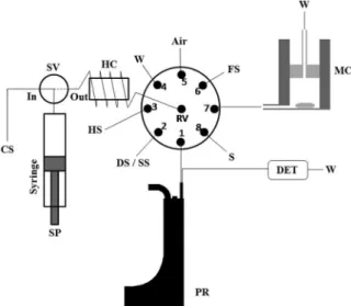
A FIAlab 3500 system (FIAlab Instruments, Bellevue, WA, USA) was used in the sequential injection mode according to Figure 3. Solutions were driven by a 5.00 mL syringe pump, SP, and an eight port rotary valve, RV (Valco Instrument Co., Houston). The holding coil, HC, was made of 3 m of 0.8 mm i.d. Telon (PolyTetraFluoroEthylene, PTFE) tubing. Connection from the reactor to the low detection cell was 53.5 cm long; connection from port 1 to the reactor was 42 cm long; both were made of 0.8 mm i.d. PTFE tubing. All other tubing connections were made of 0.8 mm i.d. PTFE tubing and PTFE nuts and ferrules (Upchurch, Oak Harbor, WA, USA). A Micronal B382 spectrophotometer (Micronal, São Paulo, SP, Brazil) was used as detector itted to a 10 mm light path length low cell with 80 µL of internal volume from Hellma (Hellma GmbH& Co. Mülheimheim, Baden, Germany), performing absorbance measurements at 632 nm. Spectral curve was previously obtained in a Hitachi spectrophotometer model U-3000 using a quartz batch cell of 10 mm optical path length.
The SIA system starts the on line sampling of solutions
using the monosegmented flow analysis approach10.
Monosegments aspirated to the holding coil are directed to a mixing chamber for homogenization. Sample, reagents
and diluted HNO3 are mixed to give a final solution
containing 20 µmol L-1 of phthalocyanine at pH 2.5,
140 µmol L-1 of H
2O2 and 14 µmol L
-1 of FeSO
4. Another
1.0 mL monosegment containing the reaction mixture of the mixing chamber is aspirated by the SIA system and then pumped toward the photo-reactor and stopped for degradation. After the irradiation time, the monosegment is driven to the spectrophotometer for absorbance reading under stopped low conditions on the ‘plateau’ between the two sharp peaks generated by the air bubbles passing through the detector. Cleaning of the manifold is performed automatically by the SIA equipment by pumping the carrier (deionized water) through the system.
Results and Discussion
General performance of photo-reactor
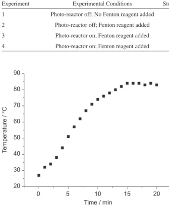
The temperature profile and time for temperature stabilization of the photo-reactor were studied before performing the blue dye degradation. Using an I.R. thermometer and measuring the reactor wall temperature after 20 min it was possible to deine the temperature proile (Figure 4); by measuring the temperature time dependence of the hottest region (12 cm below the cover), it was observed that the equipment can reach a stable temperature proile after 15 min (stabilization time) as shown in Figure 5.
Measurement with an ordinary mercury thermometer of water temperature exiting the reactor showed that the system can reach temperature equilibrium between carrier and equipment in less than 15 s. This fast equilibration time is possible due to the high area / volume ratio of the quartz tube. Water temperature was found to be around 60 °C,
Figure 3. Sequential Injection Analysis (SIA) manifold for
photo-Fenton studies. SP = Syringe pump; SV = selection valve for “in” and “out” positions of the system; HC = holding coil (3 meters long, 0.8 mm of internal diameter); CS = carrier solution (deionized water); DET = spectrophotometric detector; MC = mixing chamber (acrylic, with adjustable internal volume) containing magnetic stirrer; FS = 80 µmol L-1 FeSO
4 solution; HS = 0.50 mmol L -1 H
2O2 solution;
W = waste; PR = photo-reactor (connections to power supply not shown); SS = phthalocyanine standard solutions (calibration mode); DS = dilution solution (diluted HNO3 – pH 2.5); S = 40 µmol L-1 phthalocyanine solution.
All solutions (except carrier) were adjusted to pH 2.5 with HNO3.
Figure 4. Temperature proile at the walls of the reactor after 20 min
corresponding to approximately the mean temperature in the reactor path (65 °C).
Copper phthalocyanine dye degradation
Until entrance to the photo-reactor, the solution kept its original blue color, that is, the exposure time of the
sample to the •OH radical generated in the Fenton reaction
was not enough to start a signiicant color reduction of the
dye. Four experiments were performed using a 20 µmol L-1
dye solution under distinct experimental conditions as detailed in Table 1. Results are graphically summarized in Figure 6. Phthalocyanine dye has a linear absorbance
range from 1.0 to 10 µmol L-1; thus the original solution
signal height (experiments #1 and #2) should be about 1.2 times higher than the observed height due to linearity loss. The purpose of the irst two experiments is to show that UV irradiation is the main factor involved in color removal of the solution (experiments #3 and #4). Fenton reaction alone (experiment #2) caused a slight reduction in the color of the original solution, but it was not eficient under analysis time. A very strong decrease of the analytical signal is observed when the photo-reactor is operating; if a low concentration of the dye solution
(below 20 µmol L-1) was used, the detector could not be
Table 1. Experimental conditions employed to evaluate the effect of the photo-reactor on decolorization of phthalocyanine blue
Experiment Experimental Conditions Stopped Flow in Photo-Reactor / s Mean absorbance of the monosegment
1 Photo-reactor off; No Fenton reagent added 0 0.67 ± 0.02
2 Photo-reactor off; Fenton reagent added 0 0.61 ± 0.01
3 Photo-reactor on; Fenton reagent added 15 0.05 ± 0.01
4 Photo-reactor on; Fenton reagent added 30 0.02 ± 0.01
Figure 5. Temperature proile dependence with time monitored 12 cm
below the reactor cover (at the walls of the reactor).
Figure 6. Grouped records of absorbance from tests of the photo-reactor
on the degradation of 20 µmol L-1 phthalocyanine blue dye solutions
(from left to the right): (1) phthalocyanine solution with photo-reactor “off”; (2) – Fenton reaction mixture without UV irradiation; (3) – Fenton reaction mixture exposed to UV irradiation under 15 s of stopped low period; (4) – Fenton reaction mixture exposed to UV irradiation under 30 s of stopped low period.
able to register any signal from the remaining dye under operational conditions. Considering the calibration curve, the color removal percentage reached 97%.
Conclusions
Preliminary tests have shown that the proposed photo-reactor could be used to study the degradation of matrices by the photo-Fenton reaction. It also suggests an industrially feasible pre-treatment process because fast color removal was achieved in a very short period of time, a feature that would not be possible by using only direct
biological treatments11. Future works will show detailed
study for phthalocyanine blue dye and how to get fast and reliable optimization of the degradation conditions with
SIA manifolds.12
Acknowledgements
References
1. Huang, C. P.; Dong, C.; Tang, Z.; Waste Manage.1993, 13, 361. 2. Nogueira, R. F. P.; Trovó, A. G.; da Silva, M. R. A; Vila, R. D.;
Quim. Nova 2007, 30, 400.
3. Fenton, H. J. H.; J. Chem. Soc.1894, 65, 899.
4. Pignatello, J. J.; Oliveros, E.; MacKay, A.; Crit. Rev. Environ. Sci. Technol.2006,36, 1.
5. Raj, C. B. C.; Quen, H. L.; Chem. Eng. Sci.2005, 60, 5305. 6. Miró, M.; Hansen, E. H.; Trends Anal. Chem.2006, 25, 267. 7. Ruzicka, J.; Marshall, G. D.; Anal. Chim. Acta1990, 237, 329. 8. dos Santos, A. C. V.; Masini, J. C.; Talanta 2009, 77, 1081.
9. Cavicchioli, A.; Gutz, I. G. R.; Anal. Chim. Acta2001, 445, 127.
10. Pasquini, C.; Oliveira, W. A.; Anal. Chem.1985, 57, 2575. 11. Martínez, N. S. S.; Fernández, J. F.; Segura, X. F.; Ferrer, A.
S.; J. Hazard. Mater. 2003, B101, 315.
12. dos Santos, A. C. V.; Masini, J. C.; Microchem. J.2009, 93, 110.
Received: December 8, 2008
Web Release Date: October 9, 2009