DO:
D 10.1590/S1516-14392011005000077
Si
3N
4Ceramic Cutting Tool Sintered with CeO
2and Al
2O
3Additives with AlCrN Coating
José Vitor Candido Souzaa,b*, Olivério Moreira de Macedo Silvac, Maria do Carmo Andrade Nonoa,
João Paulo Barros Machadoa, Marcelo Pimentad, Marcos Valério Ribeiroe
a
Instituto Nacional de Pesquisas Espaciais – INPE, Av. dos Astronautas, 1.758,
CEP 12245-970, São José dos Campos, SP, Brazil
b
Centro Universitário de Volta Redonda – UNIFOA, Av. Lucas Evangelistas, 862,
CEP 27215-530, Volta Redonda, RJ, Brazil
c
Departamento de Ciência e Tecnologia Aeroespacial - DCTA, Divisão de Materiais - AMR,
Instituto de Aeronáutica e Espaço - IAE, Praça Marechal do Ar Eduardo Gomes, 50,
CEP 12228-904, São José dos Campos, SP, Brazil
d
Oerlikon Balzers Revestimentos Metálicos Ltda., Rua Balzers, 250, Parque Industrial,
CEP 13213-084, Jundiaí, SP, Brazil
e
Faculdade de Engenharia de Guaratinguetá – FEG, Universidade Estadual Paulista – UNESP,
Av. Ariberto Ferreira da Cunha, 333, CEP 12516-410, Guaratinguetá, SP, Brazil
Received: March 24, 2011; Revised: September 23, 2011
Ceramic cutting tools are showing a growing market perspective in terms of application on machining
operations due to their high hardness, wear resistance, and machining without a cutting luid, therefore are
good candidates for cast iron and Nickel superalloys machining. The objective of the present paper was the development of Si3N4 based ceramic cutting insert, characterization of its physical and mechanical properties, and subsequent coating with AlCrN using a PVD method. The characterization of the coating was made using
an optical proiler, XRD, AFM and microhardness tester. The results showed that the tool presented a fracture
toughness of 6.43 MPa.m1/2 and hardness of 16 GPa. The hardness reached 31 GPa after coating. The machining tests showed a decrease on workpiece roughness when machining with coated insert, in comparison with the uncoated cutting tool. Probably this fact is related to hardness, roughness and topography of AlCrN.
Keywords: AlCrN, ceramic cutting tool, mechanical properties, coating
*e-mail: [email protected]
1. Introduction
Generally, unconventional or advanced machining processes are used only when no other traditional machining process can meet the
necessary requirements eficiently and economically. It is important
to note that most of advanced machining processes incur relatively higher initial investment, maintenance, operating, and tooling costs. Beyond that, the optimal choice of process parameters is essential
to increase the eficiency of the process1. The machining is a major manufacturing process and plays a key role in the creation of wealth. Machining operations consumes a large amount of money annually worldwide. Dver US$ 100 billion is spent annually worldwide on
metal part inishing processes such as turning, milling, boring and other cutting operations. It is also known that the machining industry
converts about 10% of all the metal produced into swarf (wastage).
It is envisaged that up to 20% savings should be possible by using
the correct choice of tooling and machining conditions2.
The highest machining costs are found on high technology industries like aeronautics, aerospace, automobile, among others, that
uses dificult-to-cut alloys. In the manufacture of these materials it is necessary to use speciic cutting tools like cubic boron nitride (CBN),
and hard coated tools (diamond, titanium nitride), that present a high wear resistance3. However, the high cost of these cutting tools is a negative factor of them.
The materials used in the fabrication of ceramic cutting tools present important properties like: a) high hardness, b) good chemical
stability, c) stable mechanical properties on high temperatures, and d) high wear resistance. Brittleness is the key propertie that needs to be improved and this can be achieved with the use of additives that enhance the fracture toughness4.
Recently, machining tests on gray and vermicular cast iron showed the advances on the properties of Si3N4 based ceramic cutting tools. It was possible by the combination of properties like mechanical
resistance on high temperatures, fracture toughness, wear resistance and chemical stability5.
Several researchers have established that hard coatings deposited on tool, by different physical vapor deposition methods (PVD), can
dramatically change its performance. In most cases, AlCrN coating
not only help reducing the wear and increasing the tool life but also improve strength and chemical inertness, reduce friction, and improve the stability at high temperatures6.
Dry machining will be considered as a necessity for manufacturing industries in the near future and it is ecologically desirable. Companies will be compelled to consider dry machining to enforce environmental protection laws for occupational safety and health regulations. The advantages of dry machining include: non-pollution of the atmosphere (or water); no residue on the swarf which will be
relected in reduced disposal and cleaning costs; no danger to health.
standard deviation surface roughness were calculated. The average temperature was measured with a non-contact infrared pyrometer, with laser dot sighting pointed in the cutting nose. The pyrometer
was ixed in the carriage at 20 cm from cutting edge. All machining tests were supported by ISO 3685. The chemical composition and
mechanical properties of the gray cast iron are given in Table 1. In
the Figure 3, it can be seen the etched microstructure of gray cast iron
(optical microscope) with a pearlitic structure matrix, and a distinct lamellar graphitic lakes. It also presents, in a small amount, an iron
phosphide eutectic (light regions) and manganese sulphide stringers (darker grey circular features less than 5 μm in diameter).
3. Results and Discussion
3.1. Cutting tool properties
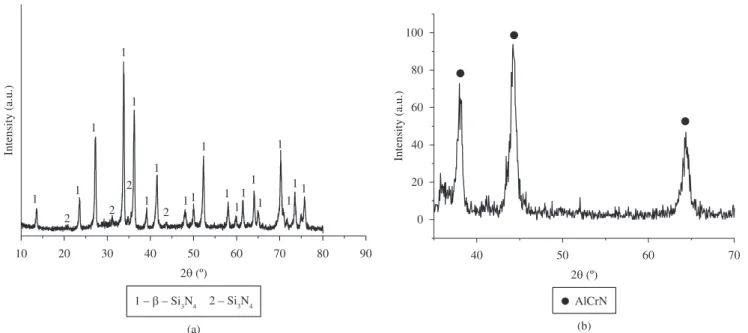
The relative density (measured density compared to theoretical density) of the sintered tools was 98.34%. The fracture toughness and hardness were respectively 6.43 MPa.m1/2 and 16 GPa. According to the X-ray diffractogram showed on Figure 4a, few reminiscent α-Si3N4
Among the factors that inluence the workpiece surface roughness
are: the process parameters (cutting speed, feed rate, etc.), friction in the cutting zone, system vibrations, cutting force variations, workpiece hardness, cutting tool material, and roughness and geometry of the cutting edge8. The effect of cutting edge roughness on the workpiece roughness will be discussed here.
In this paper, it will be shown the development of a new Si3N4 based ceramic cutting tool, sintered with CeD2 and Al2D3 additives used to reduce the insert cost and improve fracture toughness, as well
as, the AlCrN coating used mainly to enhance the supericial hardness.
There were also made turning tests on gray cast iron.
2. Materials and Methods
Silicon nitride powder 79.00 wt. (%), with an average particle size of 0.8-1.0 μm, was mixed with 7.70 wt. (%) of cerium oxide
powder, with an average particle size of 1.20 μm, and 13.30 wt. (%)
of aluminum oxide powder, with an average particle size of 1.12 μm.
The blended powders were mixed with ethylic alcohol and uniaxially
cold pressed to a square shaped compact at 80 MPa and isostatic pressing under a 300 MPa pressure. The green compacts were sintered at 1850 °C in nitrogen atmosphere (1.5 MPa) for 2.0 hours. The sintering was carried out at a heating rate of 15 °C/min from room temperature to 1500 °C and at this stage some volatile elements was totally removed from the compacts. Then, the sintering was carried out at a heating rate of 20 °C per minute from 1500-1850 °C, with a holding time for 2 hours. The sintered specimens were slowly cooled in the furnace to room temperature. Subsequently, it was cut and ground to make SNGN120408 (12.7 × 12.7 mm, 4.76 mm thickness, 0.8 mm nose radius and 0.2 mm × 20 chamfer).The XRD analysis was carried out using a computer controlled diffractometer, using CuKα radiation (wavelength 1.5406 Å). The densities of the specimens were determined using the Archimedes principle. The hardness was evaluated using a Vickers Hardness Tester Machine with a load of
20 N. The Fracture toughness was calculated by the crack length
emerging from the indentation marks, using the equation proposed by Evans and Charles for Palmqvist shaped cracks9.
AlCrN coating was made using a PVD method10. To evaluate the arithmetic average roughness (Ra) and surface topography of the inserts,
with and without AlCrN coating, it was used an optical proiler from VEECO, model WYKO NT1100. In order to observe, in details, the
morphology of the AlCrN grains, it was used an atomic force microscope
(AFM) from VEECO (Multimode V). AlCrN phase was identiied by grazing incidence X-ray diffraction (GIXRD – omega = 2°) and coating hardness was made using 0.07 N loads, eliminating the inluence of the substrate on the results. Figure 1 and 2 show uncoated and AlCrN
coated cutting tools, respectively.
After the characterization of the inserts (with and without coating), they were submitted to dry turning tests on gray cast iron in a computer numerical control (CNC) lathe (Romi, Mod. Centur 30 D) under dry cutting condition, in order to evaluate coated and uncoated cutting tools performance.
A tool holder of CSRNR 2525 M 12CEA type (offset shank with 15° [75°] side cutting edge angle, 0° insert normal clearance
and 25 × 25 × 150 mm) was used for the cutting experiments. The
cutting tests were performed at a cutting speed of 300 m/min, with constant feed rate of 0.33 mm.rev–1 and cutting depth of 1.0 mm.
For each condition, the cutting test was repeated twice. Initially, the
work material had a cylindrical shape, with 105 mm in diameter and 300 mm in length. Three surface roughness measurements were taken, distant from each other by 120° in the cylindrical work material,
after each pass. For that, it was used a surface roughness meter (Mitutoyo Surftest 402 series 178). For each pass, the average and
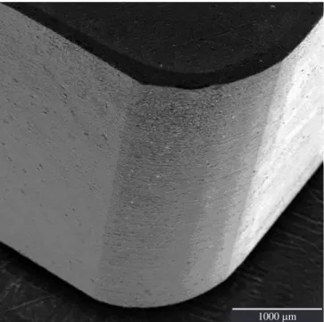
Figure 1. Photograph of silicon nitride based insert.
Figure 2. SEM micrograph of AlCrN coating deposited on ceramic cutting
and β-Si3N4 phase was identiied in the sintered insert indicating
that the sintering parameters were adequate to produce β phase, which presents important properties like high density, toughness and
hardness. It was observed that the use of Al2D3 and CeD2 additives (dissolution and precipitation; low volatilization,) promoted the formation of β-Si3N4 phase, and the fracture toughness and hardness values are characteristics of this phase11. Figure 4b presents the X-ray diffraction pattern of the coating, obtained with a grazing incident
X-ray beam. It was observed the presence of the AlCrN phase.
The substrate of the insert is β-Si3N4 with a hardness of 16 GPa. The AlCrN coating presents a hardness of 31 GPa, so the surface hardness of the insert was increased.
3.2. Surface morphology of the tool
Figure 5a shows the surface morphology (optical proiler) of
the β-Si3N4 sintered tool after grinding (0.1 µm grid size). It can be observed the grooves made from the (0.1 µm) diamond grinding
wheel (narrow indicate the grinding direction). It is important to
mention that these grooves can act as a stress raiser during turning
process, favoring premature tool failure. The Figure 5b presents the
surface topography of the AlCrN coated tool. The arithmetic average roughness (Ra) for the uncoated tool was 428 ± 13 nm, and for coated specimen was 323 ± 12 nm. It can be seen that, after coating, peaks
and valleys are smoother compared to the uncoated sample.
Figure 6a presents the surface topography (AFM) of the uncoated
tool, showing clearly the grooves from grinding step (narrow indicate
the grinding direction). Figure 6b shows the surface morphology of the AlCrN coated tool. It was observed that AlCrN grains exhibited a round shape and an equivalent average diameter of approximately
1 µm.
3.3. Turning tests
In the turning tests, for both coated and uncoated tools, it was not veriied wear or cracks on the cutting edge of the inserts, using
an optical tool makers microscope without removing the inserts
out of the cutter and after each three pass. It was not observed also
delamination of the AlCrN coating during machining.
Figure 3. Microstructure of gray cast iron (optical microscope).
Table 1. Chemical composition and mechanical properties of gray cast iron
used for cutting test.
Chemical composition of gray cast iron
C S P Si Mn Cu Cr Ni Mo
3.04 0.11 0.068 2.58 0.42 0.05 0.07 0.02 0.005 Mechanical properties
Hardness HB
Tensile strength MPa
Fatigue strength
MPa
205 245 100
The total cutting length for both tools was near 3500 m, in a total
turning time of about 12 minutes. These tools are suitable for inishing
operations on gray cast iron.
3.3.2 Machining temperature
The determination of the maximum temperature and temperature
distribution along the rake face of the cutting tool is of a particular
importance because of its controlling inluence on tool life, as
well as, the quality of the workpiece. A great part of research on thermal aspects of metal cutting operations has been concentrated on predicting the temperature on the interface zone and obtaining the temperature distributions in the cutting tool and chip. However, there is no general agreement on the procedures for estimating the average temperatures on the shear plane and the tool-chip interface.
In this paper the results obtained, give a clear idea about the values
of temperature achieved at the tool-chip interface, for both cutting
tools (AlCrN coated/uncoated). Figure 8 shows that as the insert gets in contact with the workpiece, the temperature raises rapidly. For the
uncoated cutting tools, it can be seen that the temperature rises until
a maximum of about 695 °C, and for coated insert the maximum temperature is approximately 770 °C. The temperature variation
3.3.1. Surface roughness
The proile of the workpiece surface roughness can be considered as successive movements of the tool proile at intervals of feeds. A surface with a high inishing quality is dificult to achieve because of
tool fracture, pull-out of particles and other failures during machining
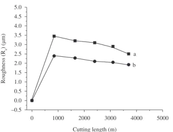
process. The results showed that the surface inish quality was better
when using an insert with AlCrN coating (below 2.3 μm) due to the small grain size of coating, higher hardness, regular (homogeneous)
topography and no lank wear. It was observed that when using uncoated ceramics cutting tools, the workpiece surface exhibited
a higher surface roughness (upper than 2.8 μm) due to irregular
topography of its cutting edge, Figure 7.
The results showed in Figure 7 also indicate that surface roughness increased substantially until a speciic time. This can
be attributed mainly to an accommodation period of the cutting
tool with the workpiece. For both cutting tools, it was noted that surface roughness decreased, after that speciic time mentioned
above, possibly due to the graphite adhesion in the nose, promoting smoothening of workpiece surface. This graphite possibly acts as a
solid lubricant (lower friction coeficient between the tool and the workpiece) and protects the tool from lank wear.
Figure 5. Optical proiler images of a β-Si3N4 cutting tool: a) grounded, and b) AlCrN coated.
(a) 301.3 µm
229.2 µm µm
–6.25 –5.00 –4.00 –2.00 –1.00 0.00 1.00 2.00
–3.00
(b)
301.3 µm 229.2 µm
µm
–4.69 –4.00 –3.50 –3.00 –2.50 –2.00 –1.50 –1.00 –0.50 0.00 0.50 1.00 1.50 2.06
The AlCrN coating promoted, compared to the uncoated insert, an increase on the hardness of the surface cutting tool, a better tribological behavior and consequently a smoother surface (lower roughness) on the gray cast iron workpiece surface after machining tests.
Both uncoated and coated inserts did not present wear or cracks after turning, for the used machining conditions.
Acknowledgements
The authors thank the inancial support of the Brazilian research inancing institutions CNPq and FAPESP.
References
1. Jain NK, Jain V and Kalyanmoy D. Dptimization of process parameters of mechanical type advanced machining processes using genetic algorithms. International Journal of Machine Tools and Manufacture. 2007; 47:900-919. http://dx.doi.org/10.1016/j.ijmachtools.2006.08.001 2. Ezugwu ED. Key improvements in the machining of difficult-to-cut aerospace superalloys. International Journal of Machine Tools and Manufacture. 2005; 45:1353-1367. http://dx.doi.org/10.1016/j. ijmachtools.2005.02.003
3. Costes JP, Guillet Y, Poulachon G and Dessoly M. Tool-life and wear mechanisms of CBN tools in machining of Inconel 718. International Journal of Machine Tools and Manufacture. 2007; 47:1081-1087. http://dx.doi.org/10.1016/j.ijmachtools.2006.09.031
4. Dkada A. Challenges of Ceramics for Structural Application. Ceramics Japan. 2005; 40(4):259-275.
5. Souza JVC, Ribeiro MV, Crnkovic SJ and Silva DMM. D desenvolvimento nacional de ferramentas cerâmicas para usinagem. Máquinas e Metais. 2008; 44:236-251.
6. Dkumiya M and Griepentrog M. Mechanical properties and tribological behavior of TiN-CrAlN and CrN-CrAlN multilayer coatings. Surface and Coatings Technology. 1999; 112:123-128. http://dx.doi.org/10.1016/ S0257-8972(98)00799-3
7. Sreejith PS and Ngoi BKA. Dry machining: Machining of the future. Journal of Materials Processing Technology. 2000; 101:287-291. http://dx.doi.org/10.1016/S0924-0136(00)00445-3
8. Bernardos PG and Vosniakos GC. Predicting surface roughness in machining: a review. International Journal of Machine Tools and Manufacture. 2003; 43:833-844. http://dx.doi.org/10.1016/S0890-6955(03)00059-2
9. Evans AG and Charles EA. Fracture toughness determination by indentation. Journal of the American Ceramic society. 1976; 59:7-8.
10. Fox-Rabinovich GS, Beake BD, Endrino JL, Veldhuis SC, Parkinson R, Shuster, LS et al. Effect of mechanical properties measured at room and elevated temperatures on the wear resistance of cutting tools with TiAlN and AlCrN coatings. Surface and coatings technology. 2006; 200(20-21):5738-5742. http://dx.doi.org/10.1016/j.surfcoat.2005.08.132 11. Souza JVC, Nono MCA, Ribeiro MV, Machado JPB and Silva DMM.
Cutting forces in turning of gray cast iron using silicon nitride based cutting tool. Materials & Design. 2009; 30:2715-2720. http://dx.doi. org/10.1016/j.matdes.2008.09.041
on Figure 8 shows that tribological behavior (friction components)
is different for AlCrN coated and uncoated inserts. There are differences of about 40-50 °C between the highest and the smallest temperature, independent of cutting tools used. Both cutting tools keep their physical and mechanical properties stable for the reached temperatures during tests.
4. Conclusions
It can be concluded that, using the experimental methodology
presented here, it was possible to develop new β-Si3N4, using Al2D3 and CeD2 as additives, with and without AlCrN coating ceramic
cutting tools, suitable for inishing operations on gray cast iron.
Figure 7. Workpiece roughness vs. cutting length, for β-Si3N4: a = uncoated; and b = AlCrN coated.