Abstract
Resistance spot welding (RSW) is a widely used joining process for fabricating sheet metal assemblies in automobile industry .In com-parison with other welding processes the RSW is faster and easier for automation. This process involves electrical, thermal and me-chanical interactions. Resistance spot welding primarily takes place by localized melting spot at the interface of the sheets followed by its quick solidification under sequential control of pressure water-cooled electrode and flow of required electric current for certain du-ration. In this work the tensile tests were studied, the results ob-tained show that the type material, the overlap length, the angle of the rolling direction and the thickness of the sheet have an influence in resistance spot welding process.
Keywords
Resistance spot welding(RSW) ; tensile tests; stress ;strain; DP450;TRIP700; HSLA350.
Experimental Study of Tensile Test
in Resistance Spot Welding Process
Lebbal Habib a Ziadi Abdelkader b Berrekia Habib c
Boukhoulda Farouk Benallel d
a Department of Mechanical Engineering,
University of Science and Technology Mohamed Boudiaf, Oran, 31000-Algeria. lebbalh@yahoo.com
b Laboratory of Intelligent Structures/
DGRSDT, CTR University of Ain Temouchent, 46000 – Algeria. aekziadi@yahoo.com
c Department of Mechanical Engineering,
University of Science and Technology Mohamed Boudiaf, Oran, 31000-Algeria. habib.doctorat@hotmail.com
d Laboratory of Mechanics of Structures
and Solids Sidi Bel Abbes Algeria 22000.Faculty of Technology. University of Sidi Bel Abbes Djillali Liabes . boukhoulda_22000@yahoo.fr.
http://dx.doi.org/10.1590/1679-78252271
1 INTRODUCTION
Spot welding or resistance spot welding (RSW) involves the joining of two or more pieces of sheet metal in localized areas or spots where melting and coalescence of a small volume of material occurs from heating caused by resistance to the flow of an electric current. This process is typically used to obtain a lap joint of sheet metal parts having a thickness of 3 mm or less. When the current is turned off this volume of molten metal cools down and solidifies beginning at its outer edges. The volume of metal from the work-pieces that have undergone heating, melting, fusion, and re-solidification is called the weld nugget.
The demand for lightweight bodies and high safety requirements has promoted the widespread use of advanced high-strength steels (AHSSs) in car body assembly. Owing to its combination of high strength and ductility, the dual-phase (DP) steel has become one of the most common used AHSSs in car body assembly. However, the major challenge of using AHSSs in the automotive industry is that they are prone to exhibit weld interfacial fracture when resistance spot welding (RSW) is used Marya and Gayden (2005). Moreover, the development of epoxy adhesive has contributed to an increasingly important role of adhesive bonding in mechanical fastening due to its high static and fatigue strength, weight reduction, etc. However, the adhesive-bonded specimens are often easily damaged in certain environmental conditions such as high humidity as Kinloch et al. (2007) and low temperature accordingly Miyoshi (1991). Therefore, the weld-bonded DP steel using epoxy adhesive which is a combination of RSW and adhesive bonding has been the subject of particular attention by Miyoshi (1995) and Darwish (2003).
Resistance spot welding is usually used in the fabrication of sheet metal assemblies. It can be used to weld materials such as low carbon steel, nickel, aluminum, titanium, copper alloy, stainless steel and High-strength low alloy steel. The resistance Spot welding process is most applied in the manu-facturing industrial fields and maintenance (car industry, aerospace and nuclear sectors, electronic and electric industries). Many published results on the mechanical behavior of spot welds have been focused on the correlation of RSW process parameters, Murat and Ahmet (2004). Have studied on the resistance spot weldability of galvanized interstitial free steel sheets with austenitic stainless steel sheets. In micro hardness measurements, the maximum hardness values were found in the middle of the weld nugget. Emin et al. (2004) had based their research on the selection of optimal welding conditions and developed new grade steels for automotive applications. The study based on impact tensile testing to spot welded sheets, the effect of nucleus size on mechanical properties in electrical resistance spot welding of chromide micro alloyed steel sheets was investigated by Aslanlar (2006).
steel (HSLA350). This aims to show an influence of angle of the rolling direction, the overlap length, type material and thickness of the sheet in resistance spot welding process.
2 EXPERIMENTAL METHOD AND PROCEDURE
Spot welding involves the joining of two or more pieces of sheet metal in localized areas where melting and coalescence of a small volume of material occurs from heating caused by resistance to the passage of an electric current. This process is typically used obtain a lap joint of sheet metal parts
.
In this work, commercial DP450, TRIP700 and HSLA350 stainless steels were used. The sheet mate-rials were cut into 140 mm X 40 mm. The dimensions and the specimens were joined as lap joints for the three materials according to the configuration shown in figure 1, using spot welding machine, type DALEX. The initial microstructures of the base metals are shown in figures 2, 3 and 4. Their chemical compositions are grouped in table 1. Before starting the welding process, it is important to make sure that the setting on spot welding machine has two important dials: the first for the welding current and the second is for the welding duration. Another important step before starting the welding process is to run on the water supply for the electrodes; this is to cool the electrodes during the welding process.40
mm
Figure 1: Dimensions of resistance spot-weld specimen (mm).
Figure 2: Initial microstructure of DP450-1,4mm.
Figure 3: Initial microstructure of TRIP700-1,4mm.
Figure 4: Initial microstructure of HSLA350-1,4mm.
Their chemical compositions are given in Table 1.
Chemical compositions [10-3%]
C Mn Si P S Al N Cu Cr Ni Mo Ti Nb V
HSLA350-1.5mm 77 515 5 8 7 44 3.5 7 12 20 2 1 23 2
DP450-1.4mm 56 1270 140 9 2.5 25 7 19 495 21 4 <2 <2 6
TRIP700-1.4mm 220 1640 46 12 1 1510 2.8 20 30 24 2.6 6 <0.5 -
Table 1: The chemical composition of the three stainless steels with different thicknesses.
2 0 µ m 3 02D3666 10 00 : 1 Nita l
In the tensile tests the Instron 8800 machine was used. Figure 5 shows the failure mode in tensile test of TRIP700 resistance spot welds.
Figure 5: Failure mode in tensile test of TRIP700 resistance spot weld.
3 RESULTS AND DISCUSSION
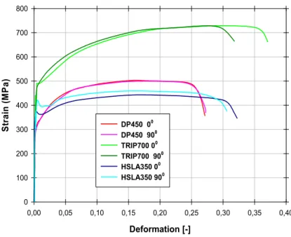
Figures 6 shows the stress-strain curves at 0 ° and 90 ° of all plates of the high strength steels used in this work. The comparison between the two graphs shows that the behavior of the steel sheets does not vary significantly with the orientation of extraction of tensile specimens.
Furthermore, the graphs show clearly the difference in the tensile strength of the three grades of steel: the TRIP steel sheets have the highest yield, strength and tensile elongation, compared to the HSLA steel which has lower values for these properties.
Deformation [-]
0,00 0,05 0,10 0,15 0,20 0,25 0,30 0,35 0,40
St
ra
in
(M
Pa
)
0 100 200 300 400 500 600 700 800
DP450 00
DP450 900
TRIP700 00
TRIP700 900
HSLA350 00
HSLA350 900
Displacement (mm)
0 1 2 3 4 5 6 7 8 9 10 11 12
Fo rc e (k N ) 0 2 4 6 8 10 12 14 16 18 20
Overlap 15 mm Overlap 15 mm Overlap 40 mm Overlap 40 mm
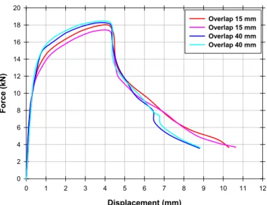
Figure 7: Influence of the length of overlap shear behavior of welded joints for steel points DP450-1,4mm.
Figure 7 shows the influence of the length of overlap on the shear behavior of welded joints for DP450-1,4mm steel, it is clear that the length of overlap has a weak effect on the shear behavior in the spot-weld as is mentioned in the following Table 2.
DP450 Peak load [kN] Maximum equivalent load [kN] (width 50 mm, thickness 1 mm)
overlap 15 mm 17,770,23 12,700,17
overlap 40 mm 18,440,11 13,170,08
Table 2: Results means shear resistance spot welded joints DP450-1,4mm steel with different overlap length.
Displacment (mm)
0 1 2 3 4 5 6 7 8 9 10 11 12
Fo rc e (K N ) 0 3 6 9 12 15 18 21 DP450 HSLA350 TRIP700
The shear behavior of spot welded joints is shown in figure 8 for different material types. The TRIP700 has the highest peak load of 19.32 kN with the maximum equivalent load equal to 13.80 kN. The following Table 3 shows the results for all materials.
Peak load[kN] Maximum equivalent load [kN](width 50 mm, thickness 1 mm)
HSLA-1,5mm 14,300,09 HSLA-1,5mm 9,530,06
DP450-1,4mm 17,770,23 DP450-1,4mm 12,700,17
TRIP700-1,4mm 19,320,18 TRIP700-1,4mm 13,800,13
Table 3: Shear behavior of spot-welded joints.
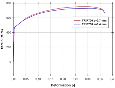
In figure 9 the Stress – strain curve of TRIP700 welding with deferent thickness sheet was carried out so it can be seen that the thickness has an influence in resistance spot welding.
Deformation [-]
0,00 0,05 0,10 0,15 0,20 0,25 0,30 0,35 0,40
Str
ai
n
(MPa
)
0 200 400 600 800
TRIP700 e=0.7 mm TRIP700 e=1.4 mm
Figure 9: Stress – strain curve of TRIP700 welding with deferent thickness sheet.
4 CONCLUSION
References
Aslanlar, S. (2006).The effect of nucleus size on mechanical properties in electrical resistance spot welding of sheets used in automotive industry. Materials and Design, 27: 125-131.
Bouyousfi, B., Sahraoui, T., Guessasma, S., Tahar Chaouch, K. (2007). Effect of process parameters on the physical characteristics of spot weld joints. Materials and Design, 28: 414-419.
Darwish, S. M. (2003). Characteristics of weld-bonded commercial aluminium sheets (B.S.1050). Int. J. Adhes. , 23(3), 169–176.
Emin, B., Dominique, K., Marc, G. (2004). Application of impact tensile testing to spot welded sheets. Journal of Materials Processing Technology, 153-154: 80-86.
Jones, T. B. (1995). Weld bonding – the mechanism and properties of weld-bonded joints. Sheet Metal Ind., 72(9), 27, 30–31.
Kinloch, A. J., Korenberg, C. F., Tan, K. T., and Watts, J. F. (2007). Crack growth in structural adhesive joints in aqueous environments. J. Mater. Sci., 42(15), 6353–6370.
Marya, M., Gayden, X. Q. (2005). Development of requirements for resistance spot welding dual-phase (DP600) steels. Part 1 – the causes of interfacial fracture. Weld. J., 84(11), 172–182.
Miyoshi, Y. (1991). State of the art in precoated steel sheet for automotive body materials in Japan. ISIJ Int., 31(1), 1–10.
Murat, V., Ahmet, A. (2004). On the resistance, spot weldability of galvanized interstitial free steel sheets with aus-tenitic stainless steel sheets. Journal of Materials Processing Technology, 153-154: 1-6.
Nizamettin, K. (2007). The influence of welding parameters on the joint strength of resistance spot welded titanium sheets. Materials and Design, 28: 420-427.
Radaj, D., Zhang, S. (1995). Geometrically nonlinear behaviour of spot welded joints in tensile and compressive shear loading. Engineering Fracture Mechanics Vol. 51, No. 2, pp. 281-294, 1995.