Fiabilitate si Durabilitate - Fiability & Durability Supplement no 1/ 2013
Editura “Academica Brâncuşi” , Târgu Jiu, ISSN 1844 – 640X 168
METHODOLOGY OF ESTABLISHING RESIDUAL LIFETIME OF
LIFTING INSTALATION BY NON-DESTRUCTIVE METHODS
eng. Florin VÎLCEANU*, prof.PhD.eng. Cătălin IANCU**,
*
S.C. TREFO Ltd.,**
Engineering Faculty,”C-tin Brâncuşi” Univ. of Tg-Jiu,Abstract: In this paper are presented first the theoretical ground for metal fatigue and then analysis
steps to be taken in order to establishing the residual lifetime of a lifting crane by non-destructive methods, while observing all the current regulations.
Keywords: methodology, lifetime, lifting installation, non-destructive methods.
1. INTRODUCTION
Metal fatigue is a process that produces premature breakage or damage of parts subjected to repeated loads.
As defined in ASTM E 1150-93 [1], fatigue is "the process of structural permanent change, localized and gradual, occurring in a material subjected to conditions that produce fluctuating stresses and deformations specific to one or more points, which may culminate in cracks or complete break after a sufficient number of fluctuations ".
For loads with tensions above the fatigue, but remaining in the elastic domain, is calculated limited sustainability, i.e. calculate the number of cycles to failure. In this way, one can develop analytical methods to quantify fatigue damage for structures to withstand repeated dynamic loads [2].
Two phases are crucial for determining the remaining duration of life on some machines operating in dynamic mode [3]:
a. Technical inspection phases: visual inspection, non-destructive control (PL, US) b. Expertise phases: static and dynamic calculations, and remaining duration of life.
After expiry of the normalized lifetime of lifting equipment (overhead cranes, cranes, etc.). arises determination of residual functioning so that under normal safety to function at a normal operating capacity or diminished but not more than 15-20%.
2. TECHNICAL INSPECTION/EXAMINATION
Necessity and opportunity of this procedure is in accordance with HG 2139/30.11.2004, regarding the classification and the useful life of equipment and in accordance with L64/21.03.2008 regarding the safe operation of pressure vessels, installations and high fuel consuming equipment.
Fiabilitate si Durabilitate - Fiability & Durability Supplement no 1/ 2013
Editura “Academica Brâncuşi” , Târgu Jiu, ISSN 1844 – 640X 169
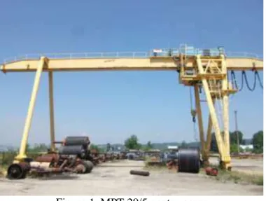
For exemplification is considered the investigation of a high gantry crane, MPT 20/5 – 20/4/4 m, with the following characteristics:
MPT - gantry crane type
20/5 - hook load: main mechanism rated load = 20 t; rated load auxiliary mechanism = 5 t 4 + 4 m - two brackets (C1 + C2)
- gauge (bridge crane) = 20 m - wheelbase (bridge crane) = 9 m - opening bracket = 4 + 4 m
- main lift height mechanism = 8 m
- auxiliary lift height mechanism = 8.75 m - speed of the crane (bridge) = 31.5 m/h - the trolley speed = 25 m / min.
The crane has an effective workduration of 19 years and it’s wanted to establish remaining duration of life in full security and working conditions.
Figure 1. MPT 20/5 gantry crane
Investigation works / technical examinations will be held as follows:
Table 1. Steps for investigation/technical examination A. Equipment inspection - which
consists of a visual inspection of the entire load bearing structure, on parts, fig. A1,2,3,4, visual inspection (VT), according to SR EN 970, check load cables -
Fiabilitate si Durabilitate - Fiability & Durability Supplement no 1/ 2013
Editura “Academica Brâncuşi” , Târgu Jiu, ISSN 1844 – 640X 170
A.3. A.4.
B. Static / dynamic analysis by FEM of strong stressed areas [4], and determining areas for non-destructive testing (PL, US), where:
2.1 Establishing input parameters:
B.1. - calculation model (fig.) B.2. - forces acting on the structure (fig.)
2.2 Analysis of results
B.3. - The most stressed zone, the central one (fig.)
B.4. - the most stressed zone between the crane foot and clamping beam; the correlation between the calculation model and the real cracks (fig.)
B.1. B.2.
B.3. B.4.
C. Non-destructive investigation /examination of previously established areas, fig. C.1. - US control of welding of main carriage taxiways, fig. C.2. - PL control of the main beam
welding area/ running trolley C.1. C.2. D. Calculation to estimate the
remaining duration of life [5], [6]
Loads used to verify the fatigue may be determined according to EN 13001, SR CENT_TS 13001-3-1, SR EN 13001-2 + A3, EN 1993-1-9-2006 (see paragraph 3). E. Technical Report writing.
Fiabilitate si Durabilitate - Fiability & Durability Supplement no 1/ 2013
Editura “Academica Brâncuşi” , Târgu Jiu, ISSN 1844 – 640X 171
3. METHODS FOR FATIGUE CALCULATION
There are currently three different methodologies for calculating fatigue, which correspond to three "theories" distinct approach [7], [8].
a. Method σ - N
Method based on stress analysis is used to calculate the unlimited durability. Primary experimental data are presented as diagrams of sustainability in coordinates "maximum stress - number of cycles to failure" (Wöhler curve). Failure is defined by the total separation of the two parts of the specimen tested.
b. Method ε − N
The method is based on the analysis of specific strains used for calculating the limited durability. It is applicable to the parts without initial cracks, stressed under elastic-plastic regime, usually made of forged steel or materials without defects. Primary experimental data are in the form of charts of little sustainability in coordinates "cyclic strain - number of cycles to failure" (Coffin-Manson curve), caused by constant amplitude tests on specimens axially tested. Failure is defined differently by the appearance of visible cracks, by sudden variations in the load or dynamic stiffness of the specimen, which define what is considered to be the period of "initiation" of fatigue cracks.
c. Fault Tolerance Method
The method is based on the analysis of crack propagation for parts with initial cracks (usually welded or riveted structures). In this case, the stress singularity at the crack tip requires the use of fracture mechanics sizes.
Primary experimental data are in the form of charts "crack propagation speed - variation of intensity of stress" drawn in logarithmic coordinates. Method permits calculating of length of a crack extending from an original size, detected by non-destructive methods, to a final dimension, comprising a safety factor to a critical value. Method involves regular inspection and acceptance of the existence of the initial crack. In practice, the application of variable amplitude solicitation decomposes into blocks of solicitation, repeated over time, each block consisting of several groups of constant amplitude stress. In Figure 2. is considered a block composed of 3 groups of sinusoidal stress of different levels (amplitudes).
Fiabilitate si Durabilitate - Fiability & Durability Supplement no 1/ 2013
Editura “Academica Brâncuşi” , Târgu Jiu, ISSN 1844 – 640X 172
If ni is the number of cycles for wich correspond the Ni durability, then each group of
stress produce the damage Di n Ni i, and the damage caused by the three groups of distinct sinusoidal block is:
1 1 2 2 3 3 ( i i) 1
D n N n N n N n N (1)
3. CONCLUSIONS
By following the steps described in this paper (table 1), based on metal fatigue theory and practice, one can perform a full study of an equipment (here the lifting crane MPT 20/5). Therefore, following this methodology it can be done the estimation of remaining of duration of life of studied equipment.
REFERENCES
[1]. ASTM E1150-87(1993) Definitions of Terms Relating to Fatigue (E 1823/1996) [2]. Lee, Y.Li., a.o. “Fatigue Testing and Analysis”, Elsevier, USA, 2005.
[3]. Verschoof, J., “Cranes – Design, Practice, and Maintenance”, Wiley & Sons, USA, 2002. [4]. Stolarski, A., a.o., “Engineering Analysis with ANSYS Software”, Elsevier, USA, 2006. [5]. STAS 11694-83/PTR1-2003 Lifting equipment. Limit deviations for dimensions for welded steel construction elements.
[6]. SR EN ISO 13920-98 Welding. General tolerances for welded constructions. [7]. Fisher, M., a.o., “A Fatigue Primer for Structural Engineers”, AISC, USA, 1998.