Glauco A. P. Caurin
Member, ABCM [email protected]
Leonardo M. Pedro
[email protected] University of São Paulo – USP Engineering School of Sao Carlos – EESC 13566-590 São Carlos, SP, BrazilHybrid Motion Planning Approach for
Robot Dexterous Hands
This paper presents a manipulation planning approach for robot hands that enables the generation of finger trajectories. The planner is based on a hybrid approach that combines discrete-continuous kinematics using a fully discrete transition system. One of the main contributions of this work consists in the representation of the universe of different submodel combinations, as states in a discrete transition system. The manipulated object geometry is taken into account and the system composed by the object and the hand is modeled as a set of closed kinematical chains. The methodology enables the synthesis of complex manipulation trajectories, when one or more fingers change the contact condition with the object. Contact condition changes include rolling contact, sliding contact, contact loss and contact establishment. Tests were carried out employing a three finger manipulation task in computer simulations and with an experimental setup.
Keywords: anthropomorphic hand; dexterous manipulation, trajectory planning
Introduction
1A significant amount of research is dedicated to provide
anthropomorphic robot hands with dexterous manipulation abilities (Bicchi and Kumar, 2000). The reason for the continuous interest on the field is that there is still a significant amount of open questions to be explored as stated in Kemp (2007) and Jenkins (2006). Among the different promising tasks that are also described in Weghe et al., (2004), the present work contributes to (a) the syntheses of finger trajectories that produce dexterous object manipulation and; (b) the analysis of object manipulation process as a hybrid discrete-continuous problem.
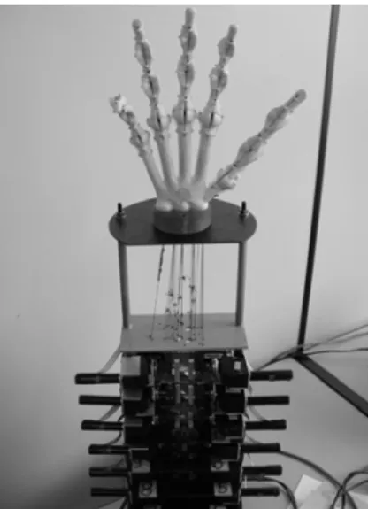
The trajectory planner system presented here is based on a set of kinematical models obtained from different combinations and interactions between the fingers and the object being manipulated. The movement requirements are centered on the object rather then on the fingers. The approach is inspired by the movements of the human hand. As an implementation example, the Kanguera Hand (Benante et al., 2007) is adopted (see Fig. 1).
Figure 1. The Kanguera Hand structure using polyurethane based on ricinus oil, its cable transmission system and nylon ligaments.
Paper accepted June, 2009. Technical Editor: Fernando A. Forcellini
The paper is organized as follows: first, the experimental setup is briefly described; next in section “The Kinematic Model of the Hand,” the necessary inverse kinematics considerations (position and velocity) for the trajectory planner are developed. In section “Manipulation as a Hybrid Dynamical System Task,” the main contribution of this work is presented, i.e. the conversion of the grasping and manipulation tasks into a hybrid Dynamical Task. The proposed trajectory planner implementation is presented in section “Trajectory planner implementation”. The proposal is validated through the use of computer simulations and experiments with the Kanguera hand, shown in section “Trajectory Planning Results,” followed by the conclusions.
The Experimental Setup
The current version of the Kanguera hand is a cable driven mechanism with 5 fingers, 3 joints in each finger and actuators remotely located at the structure basis. To cope with the trajectory planner experimental requirements, the Kanguera is provided with small Ø13 mm external housing diameter servomotors. These 3.0 W servomotors are combined with 4000:1 mechanical gears that deliver 52 Nmm nominal operational torque output and 941 rpm maximal output speed. The servomotors have also incremental encoders (16 counts per turn) integrated.
The computational hardware is based on a GE FANUC CV1 microcontroller board with a G4 processor and mounted on a standard compact PCI bus. A CanOpen bus directly connects the microcontroller board to the EPOS motor drivers. The EPOS drivers assume the individual position joint level position control. Compact PCI (cPCI) carrier boards can also extend the system capacity for digital and analogical communication required by the sensors and actuators (see Fig. 2).
Figure 2. Experimental setup created to implement the automatic trajectory planning approach.
The Kinematic Model of the Hand
The method used to model the system is focused on the spatial movements of the object with respect to a reference coordinate frame fixed on the Kanguera wrist. The motions for each finger are obtained as a function of the object movements. The motions required for each finger joint arrive as a consequence of the kinematical equations solution.
Each one of the Kanguera fingers has 3 freely commanded degrees of freedom (DOF), and each one of the fingers is interpreted as a single independent robot. As a consequence, the hand when not in contact with an object has 15 DOF.
Inverse Kinematics at Position Level
The kinematical models developed for manipulation purposes take into account the contact establishment and loss. In this way, the model changes as a function of the number of fingers in contact with the object and the number of fingers that are moving without constraints (free fingers). Therefore, the model used to represent, e.g. all five fingers grasping an object, is different from the model used when all the fingers are freely moving in space.
However, the approach of creating a model for each single manipulation condition, despite completely solving the modeling task, implies in a redundant and unnecessarily more complex representation. Here an alternative procedure is proposed for the representation of different manipulation conditions. From the manipulation point of view, each contact condition change is interpreted as a state change. The concept of changing state will be used to identify basic units or functional submodel corresponding to each kinematical closed chain that composes the system built by the five-finger hand and the object. Figure 3 shows graphically how a kinematical chain is built.
It is well known that the number of independent kinematical chains nL may be calculated as the difference between the number of
joints (nG) and the number of moving bodies (nB) on the mechanism:
B G L n n
n = − (1)
To model each finger in an independent kinematical chain, generating a submodel for each finger, an additional virtual joint (Campos et al., 2005) is introduced connecting the object to the reference frame origin on the wrist. The closed kinematical chain representation is valid even when there is a contact loss (or establishment) between the finger tip and the object. As explained in
the sequence, the changes only affect the number of bodies and joints of each chain (submodel). To represent any manipulation condition, three basic closed kinematical chain submodels types are sufficient.
Figure 3. A form representation of how the boundary conditions are created, taking the thumb as an example. The constraint equations are defined cutting the kinematical chain in two different joints (dashed line).
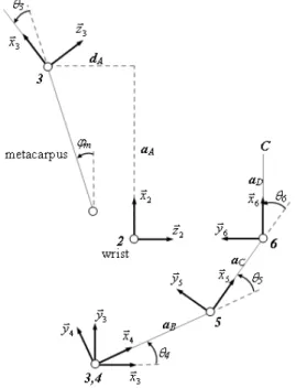
A first submodel considers the rolling contact type (Murray and Sastry, 1994). The strategy used to solve the kinematical equations for each finger initiates by “cutting” two of the mechanism joints, producing a mechanism upper part and a lower part. The lower part is composed by the object (for example, a pencil), its “virtual” joint with 6 DOF (vectors represented by solid lines in Fig. 3), and the metacarpus (vector OB for the thumb finger).
The mechanism upper part resulting from the virtual cut of the joints is illustrated in Fig. 4. The approach prepares the equations to directly return the finger joint coordinates.
For an isolated finger it is assumed that all the coordinates in the lower mechanism part are previously known and may be represented by Eq. (2), while Eq. (3) represents the upper part of the mechanism.
+ +
+
+ +
−
+ +
+ −
+
=
γ β β γ β
γ β α γ α γ
α β α γ
α β
γ β α α γ γ
α β γ α
β α
s c C s R C -c c C O R O B
-) (
) (
) s s c + s ( - c R C + ) s s + s c ( c R C
+ c c R C + O R O B
-y x z
z z
y z
x x x
R R
s s s c c R C s c s s c R C
s c R C O R O B
B C z y
x y y
(2)
The vector BC may also be expressed by:
+ +
+ + =
0 56 5
56 5
θ θ
θ θ
s a s a a
c a c a a
BC B C D
D C B
(3)
with
)
cos( 5
5 θ
θ =
c and
c
θ
56=
cos(
θ
5+
θ
6)
Combining Eq. (2) and Eq. (3) and assuming, as stated before, that the values in Eq. (2) are previously known, the values θ5 and θ6 can then be calculated.
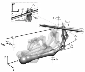
The details in Fig. 3 and Fig. 5 show that the contact is modeled using a classical mechanics approach, where the object is virtually expanded (dashed line) enabling use of a point contact model in P1.
Figure 5. The finger, the object and the virtual joint compose the kinematical closed chain representing a rolling finger contact submodel.
This submodel receives as input the object center of gravity
coordinates x, y, z and the angular orientation α, β and γ of the object with respect to the reference coordinate frame placed on the robot wrist.
As output, the submodel delivers the angular coordinates of the
corresponding finger θ3, θ 4, θ 5and θ 6.
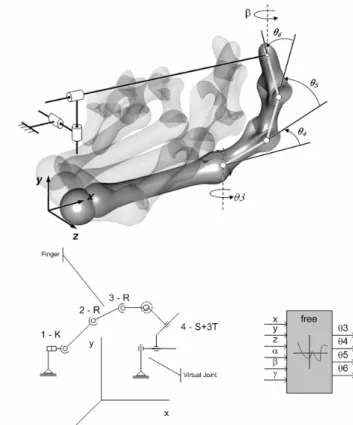
For better understanding of this kinematical model, Fig. 6 illustrates a simplified schema of the bodies and joints of the kinematical closed chain. The arrows show the solution direction for the inverse kinematics in a compact form. The use of interconnected functional blocks simplifies the task of building and visualizing the variable structure that compose the complete hand model. A variable structure allows representing all the different manipulation conditions.
Figure 6. Simplified schema for the submodel that considers a rolling contact type between the finger tip and the object. The functional block may be understood as a nonlinear unit. K – Kardan Joint. R – Rotatory Joint. S – Spherical Joint. T – Translatory Joint.
The coordinates ξ1 and ξ2 that also appear in the block describe the relative angular coordinates for the Kardan joint type used to model the rolling contact.
Using the Grübler Criteria it is possible to verify that this closed chain submodel has 6 DOF.
A second kinematical chain submodel was conceived to describe sliding contact condition between the finger and the object. The adopted submodel is shown in Fig. 7. In this case, there is no change in the number of bodies; however, the joint used to model the sliding contact requires additionally 2 DOF. Therefore, the resulting closed kinematical chain has a total of 8 DOF, and to calculate the inverse kinematics, it is consequently necessary to receive additional information when compared to the previous sliding free model. For trajectory planning purposes it is assumed that the sliding coordinates s1 and s2 may be imposed.
The third and last functional block was conceived to represent the free movements of a finger in space. In the case of a free finger x, y, and z coordinates represent the finger tip coordinates with respect to the reference frame. Figure 8 illustrates the fact that even for the free finger the submodel still corresponds to a closed kinematical chain. A corresponding functional block was created for this third submodel. Figure 8 presents this submodel with 4 DOF.
Figure 8. Submodel considering no contact between the finger and the object. The functional block represents the same submodel with the necessary signal flow to solve the inverse kinematics problem.
Complete models of the hand established in each different situation may now be constructed using combinations of the three submodels previously presented (roll, slide and free submodel).
As a combination example, Fig. 9 shows the generated topology to manipulate an object using three fingers assuming they have rolling contact and that the other two fingers are free and stationary.
Inverse Kinematics of the Hand at Velocity Level
The previous section constructed the inverse kinematic basis that is required to transform 3D paths into joint space desired position sequences. The definition of the sequence of positions (path) is a necessary condition for the implementation of the trajectory planner. Further time constrains between the different finger positioning must be imposed to guarantee completeness to the object movement coordination. The current implementation use conventional linear functions of time with parabolic blends at the beginning and at the end of individual position sequence.
To extend the solution to velocity and acceleration levels, the kinematical constrains are first differentiated and then also organized in functional blocks for velocity, respectively acceleration level.
Let’s take for example the second kinematical chain submodel that describes sliding condition between the finger and the object. Its
constrains where expressed at position level by Eqs. (2) and (3) together. Differentiating this constrains with respect to time, the following relation is obtained at velocity level:
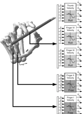
x y z α β γ Roll Thumb Position θ θ θ θ 35 45 55 65 x y z α β γ Roll θ θ θ θ 34 44 54 64 x y z α β γ Roll θ θ θ θ 33 43 53 63 Finger IV Position Finger III Position x y z α β γ Free Finger II Position θ θ θ θ 32 42 52 62 x y z α β γ θ θ θ θ 31 41 51 61 Finger I Position Free 2 2 2 2 2 2 1 1 1 1 1 1
Figure 9. Model construction using 2 submodel types. This model may be interpreted as a manipulation state where three fingers contact the object and the remaining two are free. The functional blocks give a signal flow (solution) interpretation. For simplicity reasons the ξ1 and ξ2angles where not presented. = − + + + + − − − + + − + + + + − + + + − + + + + + − + 0 0 0 ) s RC c RC ( )) s RC c RC ( s c RC ( -) ( c a ) s s s c c c c s s s -c s (c RC ) s c c s s s c s + s s c c (-s RC ) ( s a ) s s c c s c c c s c + c s (-s RC ) s s c s c s c c + s s s c (-c RC s c RC + c s RC -z y y z x 6 5 56 5 5 C z y 6 5 56 5 5 C z y x x γ γ γ β β γ γ β β θ θ θ θ θ γ γ β α γ γ α β γ β α α γ α α γ β α γ γ α γ γ β α β γ β α α γ β α α γ α β β α α α β θ θ θ θ θ γ γ β α γ γ α β γ β α α γ α α γ β α γ γ α γ γ β α β γ β α α γ β α α γ α β β α α β α c s a c c RC s s RC s a D x x D (4)
As expected, linear relations are derived and a corresponding functional block at velocity level can also be constructed (see Fig. 10).
x y z
α β γ
. . . . .
. Roll
Thumb Velocity
θ
θ
θ
θ
.
.
.
.
35
45
55 65
x y z
α β γ
. . . . .
. Roll
θ
θ
θ
θ
.
.
.
.
34
44
54 64
x y z
α β γ
. . . . .
. Roll
θ
θ
θ
θ
.
.
.
.
33
43 53 63 Finger IV
Velocity
Finger III Velocity
x y z
α β γ
. . . . .
. Free
Finger II Velocity
θ
θ
θ
θ
.
.
.
.
32
42
52 62
x y z
α β γ
. . . . .
.
θ
θ
θ
θ
.
.
.
.
31
41
51 61 Finger I Velocity
Free
2
2 2
2 2 2
1 1 1 1 1 1
Figure 10. Model construction using 2 submodels: Roll and Free. The functional blocks give a signal flow (solution) for the inverse kinematics at
velocity level. For simplicity reasons the ξ1 and ξ2angles are not
presented.
Manipulation as a Hybrid Dynamical System Task
An important part of the manipulation process deals with multiple contact modes and mode switching sequences. The fingers and the object dynamically creates or disconnect closed kinematical chains, as the dexterous manipulation forms different handling mechanisms with relative rolling and sliding motion combinations between the fingers and the objects surfaces. There are also manipulation conditions where the fingers are simply stationary or even moving freely in space without contacting any object. As stated in Yashima and Yamaguchi (2003), these complex mechanical interactions, which involves both nonlinear dynamics, as well as unilateral discrete contact events, make the overall hand-object system naturally a hybrid system. Modeling multi-fingered hands as hybrid system has already been adopted in Henzinger (1996) and Albuquerque et al. (2005), but both works are restricted to the use of heuristic rules.
Based on the Theory of Hybrid Automata (Henzinger, 1996), it is possible to abstract the mixed discrete-continuous dynamics using a fully discrete transition system. One of the main contributions of this work consists in the representation of the universe of different submodel combinations, represented as states in a discrete transition system.
The three different types of submodels when applied to build a model of an anthropomorphic hand generate a set Q with 243 (35) possible states. Each state corresponds to a different kind of interaction, i.e., a different grasp configuration between the object and the robot hand.
To help in the visualization of all possible states a graphical representation was created associating each state to a corresponding number sequence illustrated in Fig. 11. Each number sequence corresponds to a different manipulation condition. There is a single combination for no contact condition, ten combinations for single finger contact, 40 sequences for the possible two-finger
combinations, 80 combinations corresponding to three-finger contacts, another 80 possibilities for a 4-finger contact and finally 32 different states for a 5-finger contact.
Figure 11. Representation of all possible models for a 5-finger hand using 3 submodels.
The numbered sequence describing each model identifies how the three submodels are combined to compose a complete model of the system composed by the hand and the object. The number “0” is attributed to the closed kinematical chains of a free finger. Number “1” represents the existence of a rolling contact type and number “2” is used to represent a sliding contact submodel. Each number represents the submodel of a single finger in contact with the object. The numbers from left to right correspond respectively to the little finger, ring finger, middle finger, index finger and the thumb. Therefore, the sequence 00111 represents, in a compact form, the manipulation state depicted in Fig. 9, i.e. the little and the ring finger are free and the other three fingers show a rolling contact type.
Another example: the code 22212 represents the manipulation with four fingers (little finger, ring finger, middle finger and thumb) sliding and the index finger present rolling contact.
A last example: if we simply wish to push the object on a table with the index finger, the system is also able to generate a corresponding model. In this case the model corresponds to the sequence 00010.
A finite state machine (FSM) or automaton is a model of behavior composed of a finite number of states, transitions and actions.
A FSM can be represented by a state diagram. In this kind of graph vertices represent the discrete states of the model, and the discrete dynamic changes (switches) are modeled by edges. The continuous dynamics of the mechanical system is modeled by a system of differential equations. The mechanical model of the system depends on the contact state of the hand: each contact mode determines a movement condition, and each contact change may cause a discrete change in the state of the system, as determined by a jump (transition) condition.
Definition of Hybrid automata: Adapting from Henzinger (1996), a hybrid automaton H consists of the following components:
} ,..., {x1 xn
X = representing first derivatives of X during continuous changes, and
X’ = {x’1,…,x’n} for the variable values at the conclusion of discrete change.
System graph. A finite directed multigraph (V, E). The vertices in V are called system modes. The edges in E are called model switches.
Initial, invariant and contact conditions. Three vertex labeling functions init, inv, and contact that assign to each system mode v є V three predicates. Each initial condition init(v) is a predicate whose free variables are from X. Each invariant condition inv(v) is a predicate whose free variables are from X. Each contact condition contact(v) is a predicate whose free variables are from X∪X.
Jump (transition) condition. An edge labeling function jump
that assigns a predicate to each control switch e є E. Each jump
condition jump(e) is a predicate whose free variables are from '
X
X∪ .
Events. A finite set ∑ of events and an edge labeling function event E that assigns to each system switch an event.
Trajectory Planner Implementation
In this section the tools created for the trajectory planning process are presented. The submodels shown in sections “The Kinematic Model of the Hand” and “Manipulation as a Hybrid Dynamical System Task” are combined to provide a manipulation sequence. A trajectory planning example is presented for a special combination of three manipulation fingers and two free fingers.
The trajectory planner working principle is similar to the principles used in conventional industrial robots trajectory planners. Basic motion primitives are made available like precision grasping, power grasping, releasing, generalized object translation and generalized object rotation and object sliding. The combination of these motion primitives allows the construction of more complex behavior as a sequence of small spatial motion parts. In this way, any arbitrary manipulation movement may be obtained by its recursive division in parts. In this work a complete rotation about an axis in space is adopted to illustrate in details the motion coordination between the fingers.
The basic motion primitives were constructed from the simple observation of the movements realized by the human hand. The proposed motion were then transferred in an approximated form to the robot hand as a coordinated sequence of finger motions as illustrated in Fig. 12 for the object rotation example.
As may be observed at Fig. 12, the proposed heuristic allows the further creation of temporal dependency for the basic movement while maintaining the finger movement coordination.
The temporal dependency is defined using conventional approach (Craig, 2005), i.e. the trajectories are handled at velocity level with the use of linear functions with parabolic transition functions. The chosen velocity profiles are imposed to the spatial path as a parameter (scalar variable).
The transitions between the different movement phases imposes the additional condition that the calculated positions need to be precisely reached, otherwise the contact with the manipulated object may be deteriorated causing undesired slippage or contact lost.
Figure 12. Coordinated finger movements which together produce the basic object rotation. In the diagrams the abscises represent the object angular displacement, whilst the ordinate axis represent just the existence (high) or absence of activation (low).
The Trajectory Planning Results
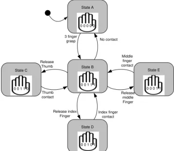
The use of the diagram in Fig. 11 allows the automatic generation of any arbitrary spatial movement required for a hand to perform dexterous object manipulation. As an application example of rotation of a pencil rotating around the reference frame y axes (illustrated in Fig. 13).
The movement is created using three free fingers and the rolling contact type submodels. The manipulation process changes the contact and non-contact states for two and three fingers.
To implement the proposed manipulation example only five (from the universe of 243 possible) states are required. These five states are isolated to indicate (see Fig. 13) more explicitly the letters labels of the 5 different states, simplifying comprehension of the model transitions, as follows: State 00000 is labeled as A; State 00111 as B; State 00110 as C; State 00101 as D; and, finally, State 00011 is labeled as E.
Release Thumb
Thumb contact
Release middle Finger Middle finger contact No contact 3 finger
grasp
State D Release index
Finger
Index finger contact
0 0 1 0 1 State B
0 0 1 1 1 State A
0 0 0 0 0
State E
0 0 0 1 1 State C
0 0 1 1 0
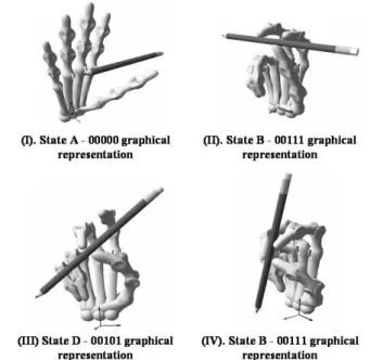
It is further assumed that the manipulation process always begins without contact with the object, that means in state A (this initialization state may also be observed in Fig. 14-I). From this state, it is assumed that it is possible to reach any of the other grasping states with an arbitrary number n of fingers. In this specific example, the transition occurs for a three finger grasp state, the state B (this state can be also observed in Fig. 14-II). Figure 14-III illustrates a state D where the thumb and the middle finger manipulate the pencil while the index finger performs repositioning (regrasping). At the same time, the other fingers are stationary.
Figure 14. Sequence of 4 frames illustrating a pencil rotating around y axes.
From Fig. 14, it is possible to observe that the manipulation system just shows which model must be used. How the model will be implemented remains an inverse kinematics question that takes the object into account. Two different conditions presented in Fig. 14-II and IV use the same model for trajectory planning purposes.
Analyzing in detail the pencil example, starting from state 00111 (Fig. 12), and performing a rotation around y axis, one may observe that the incremental variation of the pencil angular coordinates change the contact points spatial locations, and as a direct consequence they change the finger joint coordinates. All these changes can be calculated directly using the models developed in the section “The Kinematic Model of the Hand,” using as input only the desired pencil position and velocity coordinates. A sample of the input signal generated as the path for the middle finger is presented in Fig. 15.
Observing the chosen example, where the pencil starts its movement in the horizontal position, the generated trajectory converges to a periodic movement after the first time the thumb is regrasped. Similar 3D movements are obtained for the thumb and the index finger.
Even though, the two path parts have significant length differences, the same time interval of 1 (one) second is given to perform both of them. As a consequence, in the specific example explored in this paper, the finger pushing movements present much lower velocities than the velocities observed during regrasping.
Figure 15. Spatial trajectory that serve as input signal to the middle finger. The point coordinates where the transition from regrasping is emphasized.
Figure 16 presents the parameterized velocity profile obtained for the pushing part of the movement.
Figure 16. Velocity profile for trajectory part – middle finger pushing the object.
The presented velocity profile serve as input to the inverse kinematics procedure presented in section “Inverse kinematics of the hand at velocity level”. If the calculated finger joint velocities exceed any of the limits imposed by the experimental setup, it is still possible to implement the movements, simply relaxing the requirement of finishing the partial movements of each finger at the same time. If, for example, the fingers that are pushing the object are allowed to finish their movement before the regrasping motion of another finger and then required to wait for regrasping termination before requesting a new trajectory part, then the implementation of the object manipulation is still possible.
Conclusions
The adopted manipulation strategy demonstrated suitable characteristics for automation. This work opens new possibilities for manipulation centered on the object movement in 3D environment and can be used in a modular basis independently of the number of fingers, number of joints involved, and also allows the analysis of more complex object manipulation.
The human movements are taken as references for the generation of automated robot trajectories. The conversion of the movements into hybrid state diagram is responsible for converting qualitative movements into constitutive part movements with well defined limits. Each movement part generates joint movement coordinates based in rigorously define inverse kinematic approach. The obtained results show the approach capacity to follow a large variety of manipulation tasks for the corresponding large degrees of freedom number and complexity of a robot hand.
Results observed in simulations and also on experiments confirm smooth transitions between partial trajectories generated by different model states as a consequence of the necessity of every trajectory part reaching the defined transition points with zero velocity. Nonlinearities presented by individual joint paths required more robustness from the controller than did the model transitions. Future work will concentrate on improving the trajectory planning generation process automation. The experimental setup will also be changed to include new mechanical and sensor upgrades, thus improving its reliability.
Acknowledgments
The authors thank Adriano Ribeiro, Valdinei Luis Belini, and André Ribeiro Lins de Albuquerque for their valuable contributions to this work, FAPESP and CNPq for the financial support (processes number 2006/06597-5 and 301417/2007-5, respectively), and WindRiver for the VxWorks and Tornado licenses, BSPs and device drivers.
References
Albuquerque, A.R.L., Caurin, G.A.P., Mirandola A.L.A., 2005, “Dynamic modelling of the BRAHMA – Brazilian Anthropomorphic Hand”, In.International Symposium on Multibody Systems and Mechatronics.
Benante, R.C., Pedro, L.M., Massaro, L.C., Belini, V.L., Araujo, A.F. and Caurin, G.A.P., 2007, “A self-organizing state trajectory planner applied to an anthropomorphic robot hand” In: IEEE/RSJ International Conference on Intelligent Robots and Systems IROS.
Bicchi, A., Kumar, V., 2000, “Robotic grasping and contact: a review”, IEEE International Conference on Robotics and Automation, pp. 348-353.
Campos, A., Guenther, R., Martins, D., 2005, “Differential kinematics of serial manipulators using virtual chains”, Journal of the Brazilian Society
of Mechanical Science and Engeneering, Vol. 27, No. 4, pp. 345-356.
Carufel, J., Martin, E., Piedboeuf, J.C., 2000, “Control strategies for hardware-in-the-loop simulations of flexible space”, IEEE Proceedings –
Control Theory Applications. Vol. 147, No. 6, pp. 569-579.
Craig, J.J., 2005 “Introduction to Robotics: Mechanics and Control”, Boston, MA, USA: Addison-Wesley Longman Publishing Co., Inc..
Henzinger, T.A., 1996, “The theory of hybrid automata”, 11th Annual Symposium on Logic in Computer Science (LICS), IEEE Computer Society Press, pp. 278-292.
Jenkins, C., Peters, A. and Bodenheimer, R., “Uncovering success in manipulation”, 2006, Proc. RSS Workshop: Manipulation for Human Environments.
Kemp, C.C., Edsinger, A. and Torres-Jara, E., 2007, “Challenges for robot manipulation in human environments developing robots that perform useful work in everyday settings”, IEEE Robotics & Automation Magazine, Vol. 14, pp 20-29.
Miller, A.T., Allen, P.K., 2004, “GraspIt!: a versatile simulator for grasp analysis”, IEEE Robotics and Automation Magazine, Vol. 11, pp. 110-122.
Murray, R.M., Li Z. and Sastry S.S., 1994, “A Mathematical Introduction to Robotic Manipulation”, CRC Press.
Pedro, L.M., Dias, A.L., Massaro, L.C. and Caurin, G.A.P., 2008, “Dynamic modelling and hardware-in-the-loop simulation applied to a mechatronic project”, ABCM Symp. Series in Mechatronics, Vol. 3.
Vande Weghe, M. et al., 2004, “The ACT Hand: design of the skeletal structure”, IEEE International Conference on Robotics & Automation, Vol. 4, New Orleans, pp 3375-3379.
Yashima, M. and Yamaguchi, H., 2003, "On motion planning for enveloping grasp by multi-fingered hand based on switching contact modes",