Comparative analysis of design models
for concrete corbels
Análise comparativa de modelos de cálculo
para consolos de concreto
a Universidade Federal de Goiás, Goiânia, GO, Brasil; b Universidade de São Paulo, São Carlos, SP, Brasil.
Received: 17 Feb 2015 • Accepted: 05 Jan 2016 • Available Online: 31 May 2016
Abstract
Resumo
The main objective of this paper is performing a comparative analysis of some design models for precast concrete corbels. For this, it was ana-lyzed design models from Brazilian (NBR 9062) and European (EUROCODE 2) Codes and a US design handbook (PCI). Moreover, three analyti-cal models showed in the literature are analyzed. The objective of this comparative is identifying the best design models to represent the failure load of concrete corbels by the tie yields or by the concrete crushing. Moreover, it is intended to evaluate the contribution of horizontal stirrups to resistance of concrete corbels. For this, a database was assembled from test results of concrete corbels carried out by several researchers and
they are showed in the literature. The design models were applied to this database and from statistical tools, adjustments coeicients are recom -mended to be applied on these design models to take into account the results dispersion found in the analysis.
Keywords: corbels, precast concrete, design models, horizontal stirrup.
O objetivo deste trabalho é realizar uma análise comparativa de alguns modelos de cálculo para consolos de concreto pré-moldado. Para isso, são analisados os modelos de cálculo das normas brasileiras (NBR 9062) e europeia (EUROCODE 2) e de um manual de projeto
norte-ameri-cano (PCI). Além disso, são analisados três modelos de cálculo sugeridos na literatura. Busca-se nessa comparação identiicar os modelos que
melhor representam a força de ruína dos consolos, seja pelo escoamento do tirante ou pelo esmagamento do concreto da biela. Além disso,
busca-se identiicar a contribuição da armadura de costura na resistência do consolo. Para isso, foi montado um banco de dados a partir de resul
-tados de ensaios de consolos de concreto realizados por diversos pesquisadores presentes na literatura, no qual os modelos em questão foram aplicados. Utilizando-se de ferramentas estatísticas, são deinidos coeicientes de ajustes a serem aplicados aos modelos para uso em projeto e que levam em conta a dispersão de resultados encontrada na análise.
Palavras-chave: consolos, concreto pré-moldado, modelos de cálculo, armadura de costura.
D. L. ARAÚJO a
A. P. SILVA NETO a [email protected]
F. A. LOBO a [email protected]
1. Introduction
The use of precast concrete has been gradually growing and this has driven improvements in design methods for precast structures. This growth has occurred due to the advantages of using this
cons-truction process. When using precast elements there is a signiicant
reduction in the construction time, while precast concrete elements
have better workmanship and better quality control and may often be incorporated in a building without signiicant aesthetic impact.
One of most common precast elements is the corbel, which is a structural element that protrudes perpendicularly from columns and serves to support other structural elements such as beams and slabs. Despite the concrete corbel being a commonly used
element there are diferent design methods that lead to diferent
reinforcement arrangements.
Usually the design of corbels can be simpliied using the strut-and
--tie method. This simpliication is possible because tension and
compression zones arise in corbels which can be modeled like a truss. In the tension zones steel ties are placed to resist the ten-sile forces and compressive struts are represented by concrete between cracks. While not as concentrated as in the tie region, there are also some tension zones along the corbel height. In this case some Codes recommend placing supplementary horizontal stirrups along the corbels to combat these tensile stresses. For this analysis we selected the immediately applicable codes i.e. the Brazilian Code ABNT NBR 9062 [1] and the European Code EUROCODE 2 [2]. The strut-and-tie method shown in the PCI de-sign handbook [3] was also analyzed due to the wide application of this handbook in the design of precast concrete structures. These
three are design methods. These publications recommend slightly
diferent methods for the tie design. However, the main diference between them is the diferent approaches to the veriication of the
compressive strut. Further, they do not consider the supplementa-ry horizontal stirrups in their formulation, despite the fact that ABNT
NBR 9062 and EUROCODE 2 require a minimum amount of rein -forcement by horizontal stirrups.
Due to the absence of suitable design methods the horizontal stir-rups in strut-and-tie designs are often treated as part of the tension ties as in ABNT NBR 9062. Therefore, in addition to the design methods shown in the codes and manuals, three analytical ap-proaches, formulated with the inclusion of horizontal stirrup
rein-forcement, were analyzed. The irst is an adaptation proposed by
Fernandes and El Debs [4] of the classic method showed by Leo-nhardt and Mönnig [5]. The second is an adaptation of the method
proposed by Hagberg [6] and the third method was proposed by
Campione et al. [7]. These three are analytical methods.
Using statistical tools, adjustment coeicients were calculated for appli
-cation in the design of concrete structures. These coeicients take into
account the dispersion of results observed when comparing the various design methods, using a database assembled from the experimental re-sults available in the literature [8-21]. This database consists of 62 short corbels designs (with a/d ratio between 0.5 and 1.0) with concrete com-pressive strengths ranging from 25 MPa to 105 MPa. Finally, only corbels tested without the presence of horizontal force were considered.
2. Design methods for Corbels
The design methods shown in codes and manuals are intended
Figure 1 – (a) Truss geometry and (b) width of strut from the ABNT NBR 9062 [1] design method
for use by those designing concrete structures. Therefore, these
equations are formulated in such a way as to give the amount of tie reinforcement required based on the factored force on the corbel and on its geometry. After this the compressive strut is veriied to avoid concrete crushing. However, for the purpose of analyzing the accuracy of each method its equations must be modiied to make
it possible to obtain the maximum force on a corbel based on its geometry, amount of tie reinforcement and compressive concrete strength. In this way this force can be compared to the maximum strength of corbels present in the experimental database i.e. the strength limited by either the yield point of the tension tie or the concrete crushing limit on the compressive strut.
This section lays out the equations obtained from the six design methods chosen for analysis. The irst three methods are based on strut-and-tie technology and provide a ixed geometry for the
truss without considering the presence of the horizontal stirrups. The other three analytical methods chosen consider the presence of the horizontal stirrups in the corbel resistant mechanism
formu-lation. In the irst two analytical methods, horizontal stirrups are
considered by modifying the position of the tension tie so that it forms an alternative truss. The compressive strut is taken to have a constant width. The third analytical method proposes a seconda-ry truss formed by horizontal stirrups that resists part of the force applied on the corbel. In this method the strut width varies as a function of the balance of bending moments on the corbel.
2.1 ABNT NBR 9062 design method
The irst design method analyzed is the Brazilian Code ABNT NBR
9062 [1] for the design and execution of precast concrete structu-res. In this the corbel is modeled by the strut-and-tie method sho-wn in Figure 1a. In this method failure may occur by the yielding of the tension tie or by the crushing of the compressive strut. This method does not cover the design of the nodal zone of the truss. According to ABNT NBR 9062 the area of the tension tie (As) is
determined by equation (1).
(1)
yd d sf
V
d
a
A
÷
ø
ö
ç
è
æ
+
=
0
1,
where a is the distance from the vertical load applied to the corbel and column face, d is the distance from extreme compression iber to centroid of tension tie, Vd is the factored vertical load and fyd is the steel yielding stress.
Equation (2) can be used to determine the failure load of the corbel
by yield of the tension tie (Vd) using the known geometry of the corbel, the yield steel strength and tie steel area.
(2)
÷
ø
ö
ç
è
æ
+
=
d
a
f
A
V
s ydd
1,
0
For the compression strut the Code ABNT NBR 9062 proposes the geometry shown in Figure 1b. From this geometry the maximum force (Vd) due to the weight of concrete on the compressive strut can be
determined by equation (6) using the corbel’s dimensions and con
-crete strength. This equation is obtained from equation (3), where the
value of the force in the strut (Fbie) was determined by multiplying the concrete strength (fcd) by the area of the compression strut.
(3)
sin
q
=
d bieV
F
(4)
(
)
sin
sin
q
q =
dcd
b
l
V
f
(5)
(
)
sin
22
-
-
f -
q
=
cd cd
f
b
c
a
c
V
(6)
(
)
(
)
22 2
2
f
f
-+
-=
c c cd dc
c
d
a
c
c
d
b
f
V
where q is the angle of compressive strut, b is the corbel width and c is the corbel length. The mean of other variables is shown on Figure 1b.
2.2 EUROCODE 2 design method
The second studied design method is that recommended by Eu-rocode 2 [2] which has adopted the strut-and-tie method shown in
Figure 2a. The simpliied method shown in Figure 2b is given for the short corbel design which makes it equivalent to the method in
the ABNT NBR 9062 code with the addition of node 1 resistance
veriication [22].
Working out the balance of the forces on truss of Figure 2b and imposing the additional requirement of the maximum compression stress at a nodal zone, gives equation (7) for calculating the failure load due to the yielding of the tension tie corbel and equation (8) for calcu -lating the failure load due to the crushing of concrete in the compression strut.
(7)
c cd cd c cd cd s yd c cd cdd
a
b
k
f
f
b
d
f
A
k
f
f
a
b
k
f
f
V
g
g
g
÷
ø
ö
ç
è
æ
´
-÷
ø
ö
ç
è
æ
´
-+
ú
û
ù
ê
ë
é
÷
ø
ö
ç
è
æ
´
-=
1 6 1 62
6
where k1 is the EUROCODE 2 constant, that is 1.18, and gc: is the strength reduction factor for concrete.
(8)
2 2 6 1 2 2 6 164
,
0
10
250
1
2
04
,
0
10
250
1
8
,
0
d
f
f
k
b
V
a
d
f
f
k
b
V
f
d
b
V
c cd cd d c cd cd d cd d+
ú
ú
ú
ú
û
ù
ê
ê
ê
ê
ë
é
÷
ø
ö
ç
è
æ
´
-+
+
ú
ú
ú
ú
û
ù
ê
ê
ê
ê
ë
é
÷
ø
ö
ç
è
æ
´
-=
g
g
2.3 PCI design method
The third method studied is the strut-and-tie design method re-commended by the PCI design handbook [3]. This is represented by the truss shown in Figure 3a. In the case of double corbels, this
method can be modiied obtaining the truss shown in Figure 3b. The method shown in Figure 3a difers from that recommended by
ABNT NBR 9062 and EUROCODE 2 in dealing with a truss with a larger number of elements. These are an upper tension tie NO, on the corbel, and tension ties MN and MP, on the column. Moreover,
two compression struts NP and OP appear. However, in the double
corbel only one compression strut appears on each side. Thus this method reduces to that recommended by the other two Codes. The
PCI design method includes the nodal zone veriication requirement. Looking at the equilibrium of loads on the truss of Figure 3a or
Figure 3b, and checking the maximum compression stress at a
(10)
85
,
0
2
tan
f
b
V
a
d
f
A
V
f
A
V
f
F
A
cd n d y s d y s d y tir sb
g
g
q
g
g
´
+
=
Þ
=
Þ
=
0
7
,1
7
,1
22
b
f
a
V
A
f
d
b
f
V
dg
b
n cd d s yg
b
n cd\
=
-+
(11)
(
)
2
7
,1
8
,
6
7
,1
b
f
a
2A
f
d
2b
f
b
f
a
V
d n cd s y n cd n cdb
g
b
g
b
g
+
-=
(12)
nodal zone p, we obtain the distance ws that deines the geometry
of the truss:
(9)
cd n d
s
V
b
f
w
b
g
85
,
0
=
In this equation, βn is the coeicient recommended by the PCI, that
is: 1.0 for a nodal zone that receives only compressive forces; 0.8 for a nodal zone with one tie; 0.6 for a nodal zone with more than
one tie. Using this equation on equation (10), the maximum force
on the corbel (Vd) can be determined from its dimensions (b , d and
a), the yield strength of the tie steel (fy), the concrete compression strength (fcd) and the area of upper tension tie (As), as shown on
Figure 2 – (a) Truss geometry of EUROCODE 2 [2] and (b) simplified geometry
A
B
Figure 3 – (a) Truss geometry of the PCI [3] design method and (b) adapting for a double corbel
In the case of failure by the crushing of the concrete of compression strut OP, equation (13) is obtained for the maximum load. This equa -tion was obtained assuming that the nodal zone at point P presents a right angled triangle form, as laid out in the PCI [3]. When a general
triangle is considered equation (14) is obtained. This equation applies only to the OP compression strut and not to the NP compression
strut as all corbels present in the database are double and therefore do not include the NP compression strut (Figure 3b).
In these equations, hc is the width of column, cc is the concrete covering at the end of the tension tie and βs is the coeicient recommended
by the PCI, that is: 0.6 for corbels without horizontal stirrups and 0.75 for corbels with horizontal stirrups.
(
) (
)
(
)
(
)
2(
)
22 2 2
85
,
0
2
85
,
0
2
85
,
0
ú
û
ù
ê
ë
é
+
-+
+
ú
û
ù
ê
ë
é
+
-=
b
f
c
h
a
V
c
h
a
d
b
f
c
h
a
V
c
h
c
h
bd
f
V
cd n c c d c c cd n c c d c c c c cd s dgb
gb
gb
(14)
(
) (
)
(
)
(
)
ú
ú
ú
ú
ú
ú
ú
û
ù
ê
ê
ê
ê
ê
ê
ê
ë
é
ú
ú
û
ù
ê
ê
ë
é
+
-÷
ø
ö
ç
è
æ
-+
+
÷
÷
ø
ö
ç
ç
è
æ
+
-+
=
2 2 2 2 2 2 27
,1
2
2
2
1
425
,
0
d
b
f
c
h
a
V
d
c
h
d
c
h
a
d
c
h
c
h
a
b
f
V
n cd c c d c c c c s n c c c c cd n db
f
b
b
gb
2.4 Design method proposed by Fernandes
and El Debs
The fourth design method analyzed is proposed by Fernandes and El Debs [4]. In this case the authors start from the method presented by
Leonhardt and Mönnig [5] and rewrite the equations in order to take
into account the contribution of horizontal stirrups located in the region of 2d/3 from the top of the corbel (Figure 4). This limitation of height is due to the fact that horizontal stirrups outside this range have a very small deformation, not contributing to the corbel strength.
The maximum force on the corbel limited by the yield of the tension
tie is calculated as in equation (15). The indices “i” represent the
number of layers of horizontal bars including the tie. This equation was modiied from the original work to allow for the fact that not
all horizontal stirrups reach the yield strength. For this reason, a
weighting factor, deined by the ratio of the distance of each bar to
the base of the corbel (di) and the corbel height (d), was introdu-ced. This fact is demonstrated in [16] which shows that, when the tension tie yields, the other horizontal stirrups below the tie remain within their elastic range.
(15)
i i n i i i ydi si dd
z
d
d
a
z
f
A
V
9
,
0
1=
=
å
=In the case of failure by crushing of the compression strut, equation
(16) gives the maximum force on the corbel. It was assumed that
the width of the compression strut was equal to 0.2 d as originally presented by Leonhardt and Mönnig [5].
2.5 Hagberg design method
The method proposed by Hagberg [6] is similar to the method pro -posed by Leonhardt and Mönnig and also considers the contribution
of the horizontal stirrups. The diference in these methods is the in -clusion of a notional position where the tension tie and all horizontal reinforcement located at a height of 2d/3 from the top of the corbel
was concentrated. This is the equivalent height d* shown in Figure 5.
The maximum vertical load of the corbel, when the failure is by
tension tie yield, is given by equation (19):
(19)
å
=
=
n ii ydi sti
d
a
z
f
A
V
1 *
Where:
(20)
(
)
úû
ù
êë
é
+
+
-=
2 *2 * **
0
,
5
a
a
d
w
2
w
a
(21)
å
=
=
ni sd sdi i
R
R
d
d
1 *
(22)
å
=
=
=
n
i sdi
sd
i ydi si sdi
R
R
d
d
f
A
R
1
(23)
å
=
=
ni cd
ydi si
f
d
b
f
A
1 * *
*
w
(24)
cd ck
cd
f
f
f
÷
ø
ö
ç
è
æ
-=
250
1
85
,
0
*(25)
**
5
,
0
d
d
z
i=
i-
w
Equation (22), which represents the equivalent resultant tie force
(Rsdi), was also modiied here. This was to allow for the fact that
Figure 4 – Fernandes and El Debs [4] analytical method based
on the method presented by Leonhardt e Mönnig [5]
the force resisted by each bar is proportional to the ratio of the distance from the bar to the base of the corbel (di) and to the height of the corbel (d).
When corbel failure occurs by the crushing of a compression strut
the force on the strut is given by equation (26), where the abie value is shown in equation (27).
(26)
bie d cd
V
a
a
R
=
*With:
(27)
* * *
*
2
* * *
5
,
0
1
d
d
z
z
a
a
a
biew
-=
÷÷
ø
ö
çç
è
æ
+
=
The compressive stress on the strut is:
(28)
b
h
R
bie cd cd
=
s
From equations (26) and (28), the maximum vertical load Vd, on the corbel due to compression strut failure is given by equation (29).
(29)
*
a
a
b
h
f
V
cd bie bied
=
In this equation hbie , the required width of the compression strut,
can be calculating according to either of the two main design re-commendations. If we adopt the strut width as recommended by
ABNT NBR 9062 [1], equation (30) is obtained:
(30)
( )
2 2 * *
'
'
2
c
d
a
c
d
h
bie+
-=
If we use the Leonhardt and Mönnig [5] recommendation, that is,
hbie equal to 0.2 d, then equation (31) is obtained.
(31)
**
2
,
0
a
a
d
b
f
V
cd bied
=
Substituting the value of abie as given in equation (27), into equa
-tion (29), and using two diferent values for hbie we get:
(32)
2* *
*
1
2
,
0
÷÷
ø
ö
çç
è
æ
+
=
z
a
d
b
f
V
cdd
(33)
(
)
2 2 * 2
* *
*
'
1
'
2
c
d
z
a
a
c
d
b
f
V
cdd
-÷÷
ø
ö
çç
è
æ
+
-=
Equation (32) is for a strut of width equal to 0.2 d, and equation
(33) is for a strut whose width is estimated from the Brazilian Code ABNT NBR 9062 [1].
2.6 Campione et al. design method
Campione et al. [7] propose two design methods for corbels: one is for corbels without horizontal stirrups and other for corbels with horizontal stirrups. For corbels without horizontal stirrups balancing
is carried out for the simpliied truss bars shown in Figure 6. From
the balance of forces on the bars and the mechanical strength of the
materials, the equations for calculating the maximum force of corbel limited by tension tie yield, equation (34), and limited by crushing concrete on the compression strut, equation (35), are determined:
(34)
a
tan
s yd d
f
A
V
=
(35)
a
a
x
'cos
sin
c c
d
f
b
x
V
=
where α is the angle of compressive strut and f ’c is the spe-cified compressive strength of concrete. The depth of neutral axis (xc) can be determined by equation (36) and the x coeffi-cient, which estimates the compression strut strength decrea-se due to the normal tension stresdecrea-ses, can be determined by
equation (37).
(36)
c c
c s s s
s c s
c
A
E
E
bA
d
A
bE
E
E
f
x
22
;
=
4700
÷
÷
ø
ö
ç
ç
è
æ
-+
=
(37)
s y r r r
c
E
f
f
+
£
+
=
=
e
e
e
x
;
400
1
9
,
0
400
1
1
8
,
5
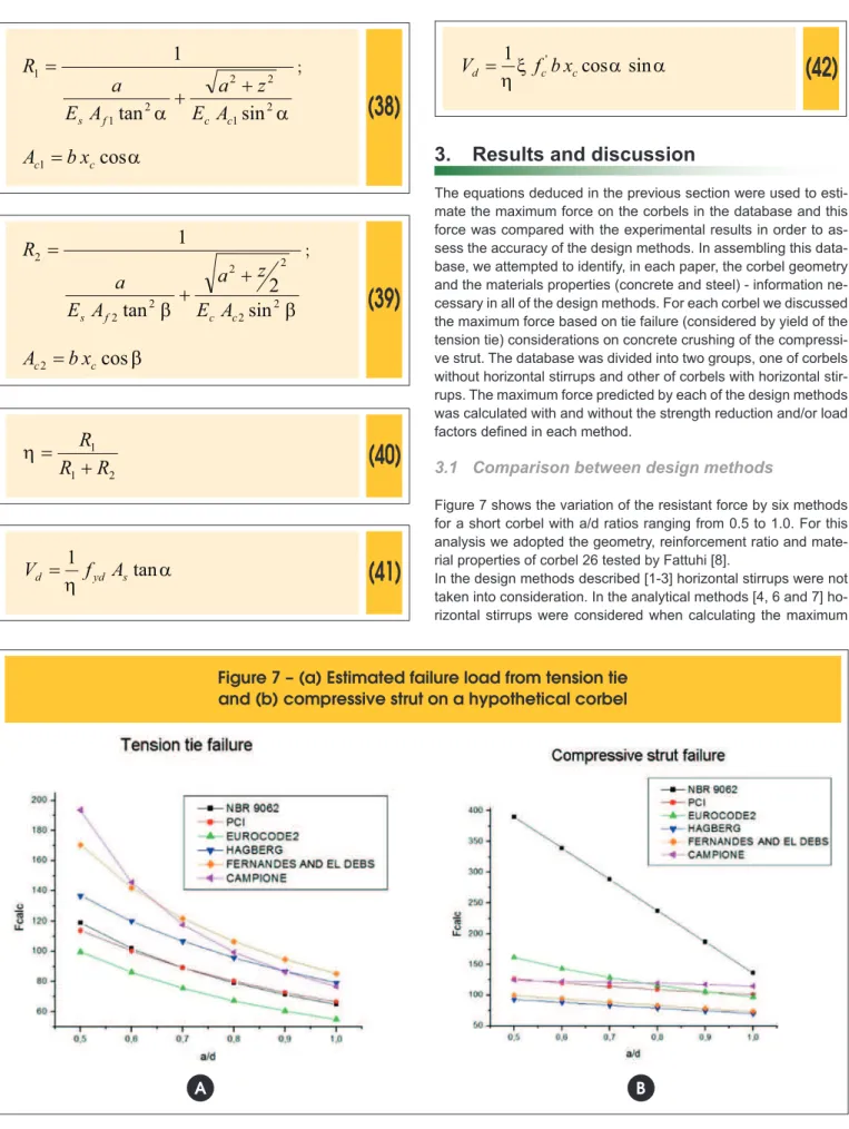
As regards the corbels with horizontal stirrups, Campione et al.
[7] propose a notional secondary truss to represent the resul-tant of forces in the horizontal stirrups. In this case, the vertical force acting on the corbel is divided between the two trusses according to the stiffness of each. Thus a coefficient h can be defined, based on the rigidity of the main truss (R1) and se-condary truss (R2), which represents the portion of the applied force on the corbel which is supported by the main truss. Using this force, it is possible to estimate the maximum force on the
corbel that will cause a failure by tension tie yield, equation
(41), or by the crushing of concrete on the compression strut
of the main truss, equation (42).
Figure 6 – Campione et al. [7] analytical method
Types of corbel
Corbel without horizontal stirrups
B
(38)
a
a
21 2 2 2
1 1
sin
tan
1
c c f
s
E
A
z
a
A
E
a
R
+
+
=
;
a
cos
1 c
c
b
x
A
=
(39)
b
b
22 2 2
2 2 2
sin
2
tan
1
c c f
s
E
A
z
a
A
E
a
R
+
+
=
;
b
cos
2 c
c
b
x
A
=
(40)
21 1
R
R
R
+
=
h
(41)
a
h
tan
1
s yd d
f
A
V
=
(42)
a
a
x
h
cos
sin
1
'c c
d
f
b
x
V
=
3. Results and discussion
The equations deduced in the previous section were used to esti -mate the maximum force on the corbels in the database and this force was compared with the experimental results in order to as-sess the accuracy of the design methods. In assembling this data-base, we attempted to identify, in each paper, the corbel geometry and the materials properties (concrete and steel) - information ne-cessary in all of the design methods. For each corbel we discussed the maximum force based on tie failure (considered by yield of the tension tie) considerations on concrete crushing of the compressi-ve strut. The database was divided into two groups, one of corbels without horizontal stirrups and other of corbels with horizontal stir-rups. The maximum force predicted by each of the design methods was calculated with and without the strength reduction and/or load
factors deined in each method.
3.1 Comparison between design methods
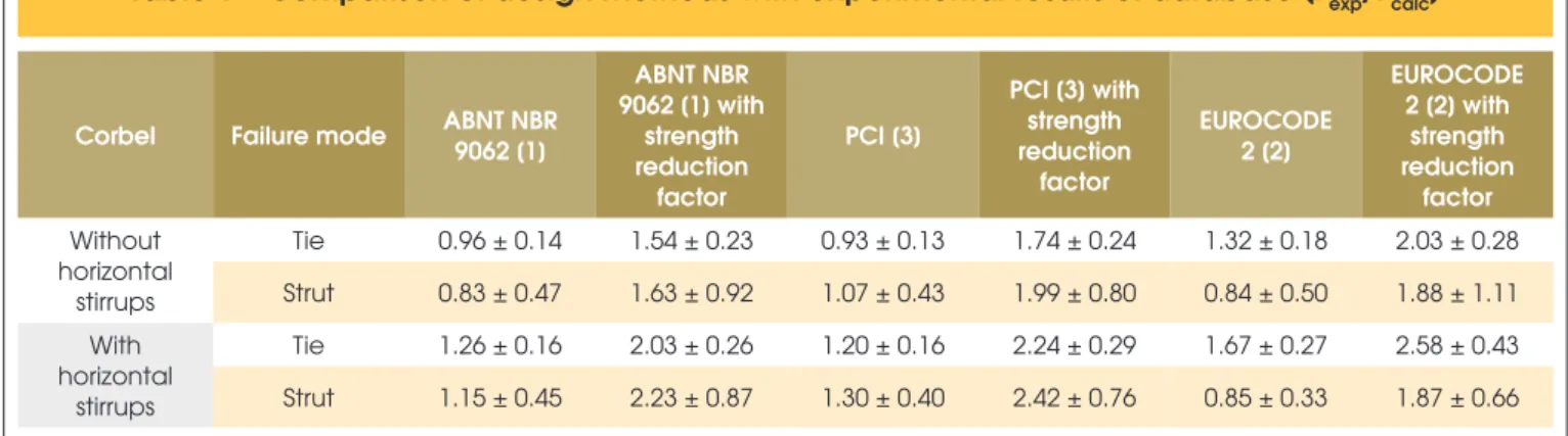
Figure 7 shows the variation of the resistant force by six methods for a short corbel with a/d ratios ranging from 0.5 to 1.0. For this analysis we adopted the geometry, reinforcement ratio and mate-rial properties of corbel 26 tested by Fattuhi [8].
In the design methods described [1-3] horizontal stirrups were not taken into consideration. In the analytical methods [4, 6 and 7] ho-rizontal stirrups were considered when calculating the maximum
Figure 7 – (a) Estimated failure load from tension tie
and (b) compressive strut on a hypothetical corbel
force. In the methods proposed by Fernandes and El Debs [4] and
Hagberg [6] based on the work of Leonhardt and Mönnig [5], the
maximum force limited by the failure of the compressive strut was
calculated using a strut width equal to 0.2d. In the case of the me-thod proposed by Campione et al. [7], it was used x coeicient as proposed in the original article.
It can be seen in Figure 7a that, for tie failure, the methods predict similar behaviors and that the force assessed by PCI [3] and ABNT NBR 9062 [1] are almost coincident. The maximum force calcula-ted taking horizontal stirrups into account [1-3] is higher than that obtained from methods without horizontal stirrups [4-6]. Finally, the
curves all have similar shapes i.e. the diference between the dife -rent methods remains approximately constant as we vary the ratio a/d, except in the method proposed by Campione et al. [7] where
the maximum force falls of more steeply with increasing a/d.
In Figure 7b a similar behavior can be seen for all of the methods, with the exception of the ABNT NBR 9062 [1] method, when failure occurred as a result of crushing of the compressive strut. In all but
the latter the a/d ratio has very little efect on the maximum force. The reason for this diference in behavior appears to be that the width of strut as speciied by ABNT NBR 9062 [1] is excessive.
From this analysis it can be seen that the method of Eurocode 2 [2] is the most conservative in estimating the tie failure load and
the methods of Fernandes and El Debs [4] and Hagberg [6] are
the most conservative in estimating the compressive strut failure
load. However, the main point of this analysis was to illustrate the diference between results from diferent design methods. This can
help to better assess concrete corbels design methods.
3.2 Assessment of design methods
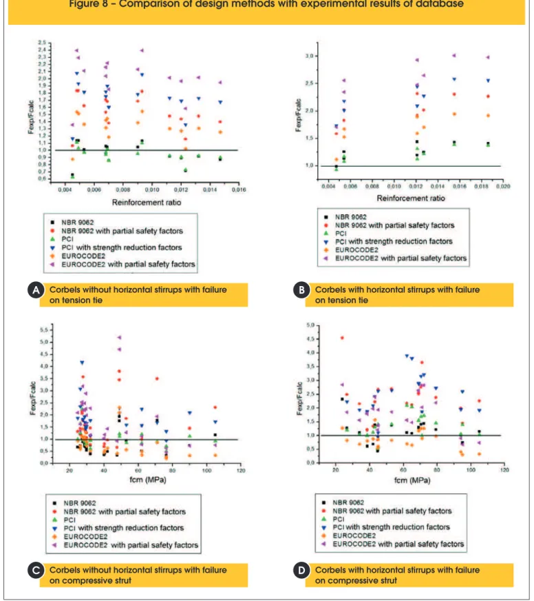
A summary of the application of the ABNT NBR 9062 [1], Eurocode 2 [2] and PCI [3] design methods for the corbels in the database is shown in Table 1. This table shows the average and standard de-viation of the ratio between experimental maximum force (Fexp) and the maximum force predicted by each of the design methods (Fcalc). In this case, the failure force of the design methods was calculated
with and without the strength reduction and/or load factors dei -ned in each method. Furthermore, the average values and not the characteristic values for the resistance of concrete and steel were used. The analysis is performed for failure by tension tie yielding and by concrete crushing on the compressive strut.
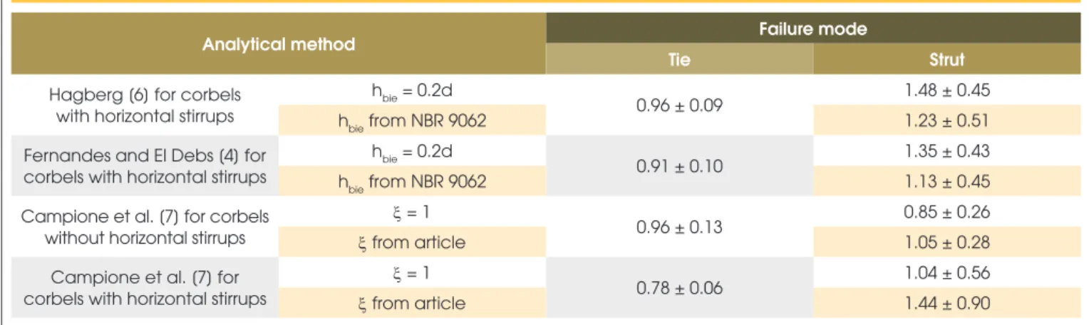
The ratio between failure forces obtained from design methods and experimental results from database is shown graphically in Figure 8. The ratio Fexp/Fcalc obtained from tie failure with various cross sectional areas is shown in Figures 8a and 8b and the ratio Fexp/Fcalc from failure of the compression strut with various concrete compressive strengths is shown in Figures 8c and 8d.
Initially, the analysis is made without consideration of strength re-duction and/or load factors set for each method. From Table 1, it can be seen that for corbels without horizontal stirrups, if the failure occurs by the tie yielding, the ABNT NBR 9062 [1] method is the
closest to the experimental results (average diference of 4%). Ho -wever, the EUROCODE 2 [2] method is more conservative
(avera-ge diference of 32%). The avera(avera-ge diference between the results
of the design methods recommended by ABNT NBR 9062 [1] and
the PCI [3] was only 3%, indicating that both methods accurately
represent the experimental results.
Analyzing failure by tie yielding of corbels with horizontal stirrups, a substantial increase in the resistance of corbels due to the presen-ce of the horizontal stirrups is noted. In this case all three design methods provide lower values than those observed in the databa-se, the PCI [3] design method being the one closest to the
expe-rimental values (average diference of 20%) and the EUROCODE 2 [2] design method the most conservative (average diference of 67%). It is worth remembering that these design methods do not take into account the efect of the horizontal stirrups on the resis -tance of the corbels. This explains the Fexp/Fcalc ratio increase when horizontal stirrups were added to corbels. In fact, previous studies have shown that the presence of horizontal stirrups can increase
the strength of a corbel by 30% to 50% when compared to the
same corbel without this reinforcement. [23]
Making a hypothesis test on the Fexp/Fcalc ratio obtained from tie
yielding failure, with a 95% conidence band, it is concluded that this ratio is signiicantly equal to 1.0 for the ABNT NBR 9062 [1]
and PCI [3] design methods. Thus it can be concluded that these design methods accurately estimate the strength of corbel without horizontal stirrups when failure occurs by tie yielding. On the other
hand, this ratio is signiicantly diferent from 1.0 for the EUROCO -DE 2 [2] design method. The same hypothesis test was applied to corbels with horizontal stirrups and it is concluded that these
de-sign methods don’t accurately estimate the strength of corbel with
horizontal stirrups when failure occurs by tie yielding.
Analyzing the resistance of corbels without horizontal stirrups
Table 1 – Comparison of design methods with experimental results of database (F
exp/F
calc)
Corbel Failure mode ABNT NBR 9062 [1]
ABNT NBR 9062 [1] with
strength reduction
factor
PCI [3]
PCI [3] with strength reduction
factor
EUROCODE 2 [2]
EUROCODE 2 [2] with
strength reduction
factor
Without horizontal
stirrups
Tie 0.96 ± 0.14 1.54 ± 0.23 0.93 ± 0.13 1.74 ± 0.24 1.32 ± 0.18 2.03 ± 0.28
Strut 0.83 ± 0.47 1.63 ± 0.92 1.07 ± 0.43 1.99 ± 0.80 0.84 ± 0.50 1.88 ± 1.11
With horizontal
stirrups
Tie 1.26 ± 0.16 2.03 ± 0.26 1.20 ± 0.16 2.24 ± 0.29 1.67 ± 0.27 2.58 ± 0.43
Figure 8 – Comparison of design methods with experimental results of database
Corbels without horizontal stirrups with failure on tension tie
Corbels without horizontal stirrups with failure on compressive strut
Corbels with horizontal stirrups with failure on tension tie
Corbels with horizontal stirrups with failure on compressive strut
B
B
B
B
A
C
B
when failure occurs by concrete crushing on the compressive strut, it can be seen from Table 1 that the design methods re-commended by ABNT NBR 9062 [1] and the EUROCODE 2 [2] may be unsafe. The design method recommended by the PCI [3]
seems to be more precise and safe, with an average diferen
-ce of 7% compared to the experimental results. However, a high
standard deviation was seen in the analysis of the compressive strut failure.
Analyzing the resistance of corbels with horizontal stirrups when failure occurs by concrete crushing of the compressive strut, the method of ABNT NBR 9062 [1] is shown to be more accurate
(average diference of 15%) and EUROCODE 2 [2] method appe -ars, on average, to be unsafe. The hypothesis test on the Fexp/ Fcalc ratio, with a 95% conidence band, is signiicantly equal to
1.0 only for the ABNT NBR 9062 [1] method. However, a high
standard deviation was also observed in the analysis of the com-pressive strut failure in corbels with horizontal stirrups.
Next, the same analysis was performed including the strength reduction and/or load factors set for each method. In this case, on average, all design methods provide values lower than those observed in the database, both for tie failure and for compres-sive strut failure. Taking into account the standard deviation of the Fexp/Fcalc ratio the design methods still provide safe values for
estimating the tie failure force. This can be conirmed by Figures
8a and 8b where Fexp/Fcalc ratios above the boundary line, that is in the safety region, were obtained for all of the corbels analyzed. The high standard deviation of the Fexp/Fcalc ratio for failure of the compressive strut suggested that the value of this ratio was loca-ted in the unsafe region from some corbels. This occurred most
frequently in corbels without horizontal stirrups and for concrete
compressive strengths greater than 60 MPa (Figure 8c). Despite this, the hypothesis test shows that the Fexp/Fcalc ratio from all the
design methods is signiicantly higher than 1.0 on corbels without
horizontal stirrups. The same analysis on corbels with horizon-tal stirrups shows that all design methods provided values lower than those observed in the database, despite the high standard deviation (Figure 8d). Therefore, it is concluded that the strength reduction and/or load factor values for all the design methods are
adequate to ensure safe design of reinforced concrete corbels
with and without horizontal stirrups.
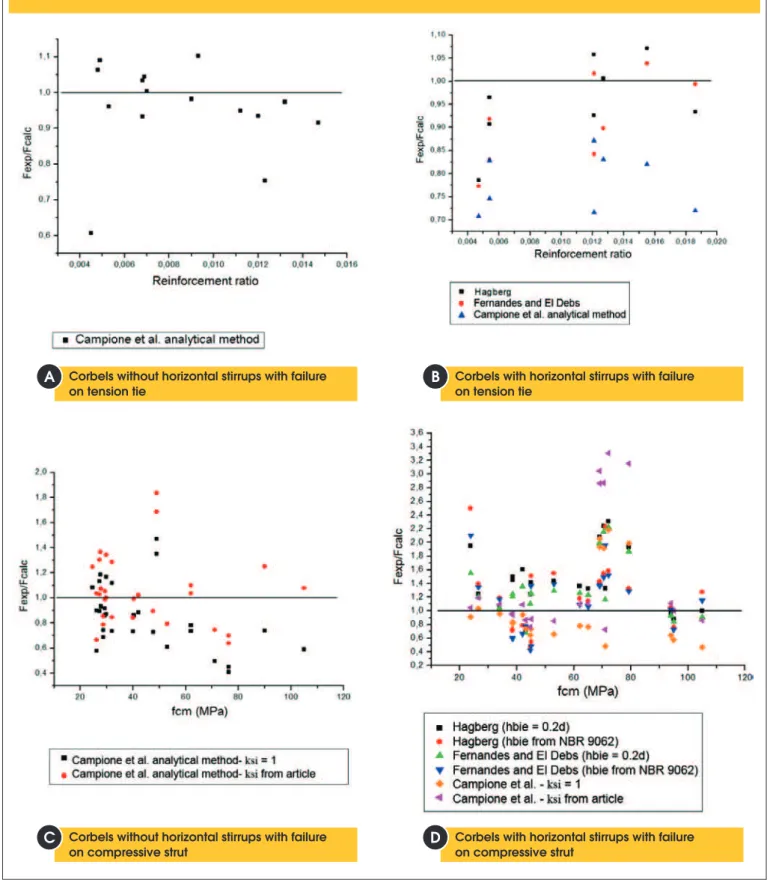
3.3 Assessment of analytical methods
It has been seen that design methods do not accurately predict the failure force by tie yielding for corbels with horizontal stirrups. Let us now consider the analytical methods proposed by Fernandes and
El Debs [4], Hagberg [6] and Campione et al. [7] which take into account the contribution of horizontal stirrups to the corbel streng-th. Table 2 summarizes the results obtained from the application of analytical methods to the database using a similar methodology as that used for the assessment of the design methods. Figure 9 shows the ratio between failure forces obtained from analytical methods and the experimental results from the database.
Two main assumptions had to be made in order to apply the analyti-cal methods to the database. Firstly, the width of compressive strut
in the methods proposed by Fernandes and El Debs [4] and Ha
-gberg [6] was initially taken as 20% of the efective corbel height
(0.2d). These methods were also analyzed with the compressive strut width determined from the procedure recommended by ABNT NBR 9062 [1]. Secondly, the compressive strut failure force from the method proposed by Campione et al. [7] was determined using
the reduction coeicient of concrete strength proposed by these
authors. This was 1. That is, it does not take into account the re-duction of the concrete compressive strength on the strut.
It can be noted from Table 2 that the method proposed by Hagberg [6] adequately represented the tie failure force for corbels with ho
-rizontal stirrups. The values were, on average, 4% higher than the
experimental values and had low standard deviation. The
hypothe-sis test showed, with a 95% conidence band, that this is the only
analytical method which accurately represents the failure force of the tests (Fexp/Fcalc = 1). The other analytical methods overestima-ted the corbel strength (Fexp/Fcalc < 1).
The analytical method proposed by Campione et al. [7]
overesti-mated the strength of corbels with horizontal stirrups by 22%, indi -cating that it was not suitable for these corbels. This is due to high rigidity of the secondary truss proposed in the method which tends
to increase the corbel strength when the coeicient h decreases. It
is suggested, therefore, that the stifness of the compressive strut
on the secondary truss proposed by these authors must be
revi-sed. However, the method proposed by Campione et al. [7] sho-wed a good agreement with the experimental results when it was
Table 2 – Comparison of analytical methods with experimental results of database (F
exp/F
calc)
Analytical method Failure mode
Tie Strut
Hagberg [6] for corbels with horizontal stirrups
hbie = 0.2d
0.96 ± 0.09 1.48 ± 0.45
hbie from NBR 9062 1.23 ± 0.51
Fernandes and El Debs [4] for corbels with horizontal stirrups
hbie = 0.2d
0.91 ± 0.10 1.35 ± 0.43
hbie from NBR 9062 1.13 ± 0.45
Campione et al. [7] for corbels without horizontal stirrups
x = 1
0.96 ± 0.13 0.85 ± 0.26
x from article 1.05 ± 0.28
Campione et al. [7] for corbels with horizontal stirrups
x = 1
0.78 ± 0.06 1.04 ± 0.56
Figure 9 – Comparison of analytical methods with experimental results of database
Corbels without horizontal stirrups with failure on tension tie
Corbels without horizontal stirrups with failure on compressive strut
Corbels with horizontal stirrups with failure on tension tie
Corbels with horizontal stirrups with failure on compressive strut
B
B
B
B
A
C
B
used to estimate the tie failure force of corbels without horizontal stirrups (Fexp/Fcalc = 1, with a 95% conidence band).
The failure force on the compressive strut estimated from the analytical methods proposed by Fernandes and El Debs [4] and
Hagberg [6] increases when the ixed value of strut width (0.2d)
was replaced by the strut width deined in ABNT NBR 9062 [1].
In this case the analytically predicted failure force showed a good approach to the experimental results albeit with a high standard deviation.
The analytical method proposed by Campione et al. [7] showed the best accuracy for predicting the failure force limited by con-crete crushing on compressive struts for corbels with and without horizontal stirrups. In the absence of the horizontal stirrups, the
diference between analytical and experimental results is only 5% when the coeicient x suggested by the authors, x <1, was used. In the case of corbels with horizontal stirrups a slightly better
ac-curacy of 4% was obtained when x = 1 was used. This shows the
positive efect of horizontal stirrups, which contribute to the coni -nement of the compressive strut and increase of the failure force. This phenomenon is represented in the analytical method by
incre-asing the value of the coeicient x.
The width of the compressive strut in the analytical method propo-sed by Campione et al. [7] is deined by the height of the neutral axis at the interface between the corbel and column (xc) which is
obtained from the lexural theory applied to this section. It is not
obtained from the classical strut-and-tie method. Thus, this pro-cedure seems to be more appropriate to apply to corbels without horizontal stirrups or to corbels with few horizontal stirrups. In this case the main tie yields before concrete crushing occurs. This was the major failure mode observed in the database. For this reason, the analytical method of Campione et al. [7] showed the lowest standard deviation when compared to experimental values obtai-ned from the database when compared to other methods. For cor-bels with horizontal stirrups an increase in the standard deviation was observed.
3.4 Adjustment coeicients for analytical methods
An important aspect in the assessment of the analytical methods is the standard deviation value obtained when these methods were compared with experimental results from database. The standard deviation from failure by tie yield was lower than failure by concrete crushing on a compressive strut. This is due to the low variation of the corbels geometry and steel yield strength when compared to
the high variation of the compressive strength of concrete. Howe -ver, the higher standard deviation can be also related to the adop-ted value of width of the compressive strut in each method, which
can be diferent from the real width on tests.
Therefore, we have determined what adjustment coeicients
need to be applied to analytical methods in order to ensure sa-fety levels similar to that of the design methods. For this, the methodology proposed by Ravindra and Galambos [24] was
used. This proposed a simpliied method for determining streng
-th reduction coeicients for design equations taking into account
the desired reliability index. Basically, the reliability of the ma-thematical method is determined from the probability that the estimated strength given by the mathematical method is higher than the real resistance of corbel. This would obviously be
un-safe. Therefore, reduction coeicients (f) should be determined which ensure that the resistance provided by the analytical me-thod is always lower than the real resistance for a certain relia-bility index (b).
Based on the simpliied method of Ravindra and Galambos [24],
and adapted for the analysis undertaken in this work, the strength
reduction coeicient (f) can be determined using equation (43),
(43)
R
V
calc
e
F
F
abf
=
exp-Where:
(44)
2 2 2
P F M
R
V
V
V
V
=
+
+
It was proposed by Ravindra and Galambos that the parameter α be set at 0.55. These authors also proposed a coeicient of varia
-tion of 9% for the material properties (VM) and 5% for the geome
-trical properties (VF) of the corbels. The coeicient VP is the
coe-icient of variation i.e. the Fexp/Fcalc ratio obtained when analytical
methods are applied to the corbels database.
From these equations the coeicient f can take values less than or greater than unity. When f < 1, the analytical method is determi-ned as being unsafe and it is necessary to reduce the resistance
estimated from analytical method by the coeicient f. If f ≥ 1, this means that the analytical method is safe for the chosen reliability index. In this work a reliability index of 4.5 was chosen. This repre-sents, approximately, a failure probability less than 10-5.
For the estimation of resistance by design methods, the strength
reduction coeicients recommended for each design method were
employed. For analytical methods, the safety criterion recommen-ded by the ABNT NBR 8681 [25] was used, that is, the average strength of materials was divided by gc = 1.4 for concrete and
gs = 1.15 for steel reinforcement. In addition, the resistance
deter-mined by all six methods was divided by gf = 1.4 in order to take
account, in a simpliied way, of the load factors used on structures design. The coeicient gn≥ 1 established by the ABNT NBR 9062 [1] for the design of corbels was not used.
From this methodology, and using Tables 1 and 2, we obtain
Table 3 which gives the values of the coeicient f for each method when failure happen by main tie yielding. This table shows that practically all of the design methods have f > 1 for corbels with or without horizontal stirrup, indicating a failure probability lower than 10-5. The only exception was when the design method
recommen-ded by ABNT NBR 9062 [1] was applied to corbels without
horizon-tal stirrups. However, in this case the coeicient f is very close to unity. The analytical methods proposed by Fernandes and El Debs
[4] and Hagberg [6] also showed f > 1 indicating a failure probability less than 10-5 when the coeicients recommended by ABNT NBR
8681 [25] were employed. The Campione et al. [7] analytical method showed f <1 due to the high standard deviation of Fexp/Fcalc ratio.
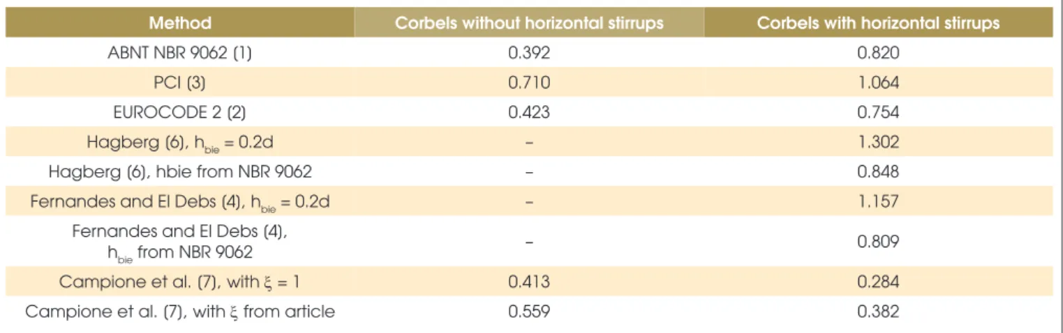
Table 4 shows the values of the coeicient f for each method when failure occurs by concrete crushing on the compressive strut. The methods proposed by the PCI [3], Fernandes and El Debs [4] and
Hagberg [6] show f > 1 for corbels with horizontal stirrups. In this
case the last two methods are safe only when a strut width of 20% of the efective corbel height was used. In all other cases a strength reduction coeicient f must be used in order to ensure a failure probability less than 10-5. This additional strength reduction coei -cient is necessary due to the high values of coei-cient VP obtained
for the Fexp/Fcalc ratio when failure occurs on the compressive strut.
However, the coeicient f obtained for these analytical methods would be higher if the characteristic strength of materials was used instead of average strength or if a failure probability better than 10-5
(b <4.5) was required.
4. Conclusions
This paper describes a comparative analysis of several design methods for precast concrete corbels. For this, six methods, in-cluding three methods with horizontal stirrups in their formulation, were compared with a database containing the results for 62 tes-ted corbels available in the literature. From this analysis the main conclusions are:
n For corbels without horizontal stirrups, the design methods of ABNT NBR 9062 [1] and PCI [3] provided the best accuracy
when failure occurs by main tie yielding. In this case, the de-sign method of EUROCODE 2 [2] was the most conservative. When failure occurs by concrete crushing on the compressive strut, the PCI [3] design method was shown to have best agre-ement with the experimental values from the corbels database.
However, a high standard deviation was observed when failure
was from the compressive strut.
n For corbels with horizontal stirrups, all design methods unde-restimated the failure strength of corbels by main tie yielding due to ignoring the contribution of the horizontal stirrups. In this
case, the analytical method proposed by Hagberg [6] showed
better agreement with the predicted strength.
n All of the methods assessed showed large standard
devia-tions when predicting the failure force of corbels with hori-zontal stirrups in the database when failure happened on the compressive strut. The method proposed by Fernandes and
El Debs [4] with the strut width deined by the ABNT NBR 9062 [1] was the best it to the failure force from the corbels database. However, the criterion of the ABNT NBR 9062 [1]
method for estimating the width of a strut was based only on the load bearing area and not on the maximum compression stress at a nodal zone on the truss geometry. The load
bea-ring area was well deined for the corbels in the database as
these were subjected to a vertical load only and have a known bearing-plate. On real precast structures with soft bearings
Table 3 – Values of the coefficient
ϕ
for methods when failure occurs on tension tie
Method Corbels without horizontal stirrups Corbels with horizontal stirrups
ABNT NBR 9062 [1] 0.980 1.357
PCI [3] 1.140 1.481
EUROCODE 2 [2] 1.329 1.590
Hagberg [6] – 1.106
Fernandes and El Debs [4] – 1.022
Campione et al. [7] 0.738 0.691
Table 4 – Values of the coefficient
ϕ
for methods when failure occurs on compressive strut
Method Corbels without horizontal stirrups Corbels with horizontal stirrups
ABNT NBR 9062 [1] 0.392 0.820
PCI [3] 0.710 1.064
EUROCODE 2 [2] 0.423 0.754
Hagberg [6], hbie = 0.2d – 1.302
Hagberg [6], hbie from NBR 9062 – 0.848
Fernandes and El Debs [4], hbie = 0.2d – 1.157
Fernandes and El Debs [4],
hbie from NBR 9062 – 0.809
Campione et al. [7], with x = 1 0.413 0.284
the load width support on corbels may be overestimated. In
this case the required width of the compressive strut may be
overestimated by the Fernandes and El Debs design method if the load width support was not accurately known. For cor-bels with soft bearings the PCI [3] design method seems to be the most appropriate for evaluating the failure force of corbels with horizontal stirrups when failure occurs on the compressi-ve strut.
n All design methods with strength reduction and/or load factors estimated a safe failure load with respect to the corbels data-base with and without horizontal stirrups.
n The method proposed by Campione et al. [7] had the best
ac-curacy for estimating the failure load for corbels in the data-base without horizontal stirrups. It also had the best accuracy in estimating the failure load from the compressive strut on corbels in the database with horizontal stirrups. This indicates that this method seems to be more appropriate to evaluate the width of strut of corbels in the database.
n All design methods and the analytical methods proposed by
Fernandes and El Debs and Hagberg estimated a safe load when failure occurs from yield of main tension tie. However,
the reliability index (b) of the design methods was higher than 7.5 due to the fact that these methods do not consider the con-tribution of horizontal stirrups on corbel resistance. Assuming a failure probability of 10-5 (b = 4.5), and considering the
con-tribution of horizontal stirrups to the corbel resistance, it may be possible to decrease the tension tie area. Further
analy-sis should be conducted to conirm this possibility, especially
adopting more accurate reliability analysis.
n A wide dispersion of estimated failure loads was observed from all methods when failure for corbels in the database was by
the compressive strut. Thus the analytical methods that best it with experimental results were adjusted with a coeicient f less
than 1.0 in order to ensure adequate safety of these methods.
The more conservative methods did not need to be adjusted. The average concrete strength rather than the characteristic strength was adopted in this analysis as the characteristic strength was unknown for the database corbels. Thus the
va-lues of the coeicient f obtained may be overly conservative. Further analysis should be carried out, in particular by adopting more accurate reliability analysis that considers the variability of strength of concrete and steel, as well as variability of geo-metry and loading.
Finally, we must emphasize the importance of checking the accu-racy of analytical methods in representing physical phenomena as they are directly related to the safety of structure designs. This can be checked by comparing the predictions of the analytical metho-ds against experimental results, as done in this paper. To do this, however, it is necessary to have an extensive database for evalu-ating the variability of material strengths and even the test method. Unfortunately, this is not always available.
5. Acknowledgements
The authors wish to thank the Brazilian National Council of
Rese-arch and Development (CNPq) for inancing this reseRese-arch (Pro -ject number 552118/2011-7) and for granting a scholarship for the authors.
6. Notation
As: Area of steel bar;
a: Distance from the vertical load applied to the corbel and colu-mn face;
b: Corbel width; c: Corbel length;
c’: Corbel length less concrete covering and diameter of tension tie; f: Diameter of bar anchor on the end tension tie;
cc: Concrete covering at the end of the tension tie;
d: Distance from extreme compression iber to centroid of ten -sion tie;
Ec: Modulus of elasticity of concrete;
Es: Modulus of elasticity of reinforcement steel; Fbie: Force acting in a strut;
fcd : Design compressive strength of concrete;
fck : Characteristic compressive strength of concrete;
fyd : Steel yielding stress, calculus value; hbie: Width of strut;
hc: Width of column;
k1: EUROCODE 2 constant, that is 1.18;
l: Horizontal length of strut;
n: Number of horizontal stirrups on the corbel; Rsd: Resultant force in the tension tie;
Rcd: Resultant force on compressive strut; Vd: Failure load of corbel;
βn: Coeicient recommended by the PCI, that is: 1.0 for a nodal
zone that receives only compressive forces; 0.8 for a nodal zone with one tie; 0.6 for a nodal zone with more than one tie;
βs: Coeicient recommended by the PCI, that is: 0.6 for corbels
without horizontal stirrups and 0.75 for corbels with horizontal stirrups;
g: Strength reduction factor recommended for PCI;
gc: Strength reduction factor for concrete; θ: Angle of strut;
ξ: Reduction coeicient for conined concrete strength; scd: Compressive stress on strut.
7. References
[1] ASSOCIAÇÃO BRASILEIRA DE NORMAS TÉCNICAS – ABNT. NBR 9062: Design and execution of precast concrete structures. Rio de Janeiro, 2006 (In Portuguese).
[2] COMITÉ EUROPÉEN DE NORMALISATION. EUROCODE 2: Design of concrete structures – Part 1.1: General rules and rules for buildings. Brussels, Belgium, 2004.
[3] PRECAST/PRESTRESSED CONCRETE INSTITUTE –
PCI. PCI Design Handbook. 7th Edition, 2010.
[4] FERNANDES, R. M.; EL DEBS, M. K. Análise da capacida-de resistente capacida-de consolos capacida-de concreto armado consicapacida-derando a contribuição da armadura de costura. Cadernos de
Enge-nharia de Estruturas, São Carlos, v.7, n.25, 2005; p.103‒128
(In Portuguese).
[5] LEONHARDT, F.; MÖNNIG, E. Construções de concreto:
Casos especiais de dimensionamento de estruturas de concreto armado. v.2.1., Rio de Janeiro: Interciência, 1978 (In Portuguese).
application of the truss analogy. ACI Journal, v.80, n.1, 1983;
p.3‒12.
[7] CAMPIONE, G.; LA MENDOLA, L.; PAPIA, M. Flexural
behaviour of concrete corbels containing ibers or wrapped
with FRP sheets. Materials and Structures, v.38, 2005;
p.617‒625.
[8] FATTUHI, N. I. Strength of SFRC corbels subjected to verti -cal load. Journal of Structural Engineering, v.116, n.3, 1990;
p.701‒718.
[9] FATTUHI, N. I. Column-load efect on reinforced concrete
corbels. Journal of Structural Engineering, v.116, n.1, 1990;
p.188‒197.
[10] FATTUHI, N. I.; HUGHES, B. P. Ductility of reinforced con
-crete corbels containing either steel iber or stirrups. ACI Ma
-terials Journal, v.86, n.6, 1989; p.644‒651.
[11] FATTUHI, N. I. Reinforced corbels made with high-strength
and various secondary reinforcements. ACI Structural
Jour-nal, v.91, n.4, 1994; p. 376‒382.
[12] FATTUHI, N. I. Reinforced corbels made with plain and i -brous concrete. ACI Structural Journal, v.91, n.5, 1994;
p.530‒536.
[13] FATTUHI, N. I. Strength of FRC corbels in lexure. Journal Structural Engineering, v. 120, n.2, 1994; p.360‒377. [14] FOSTER, J. S.; POWELL, R. E.; SELIM, H. S. Performan
-ce of high-strength concrete corbels. ACI Structural Journal,
v.93, n.5, 1996; p.555‒563.
[15] KRIZ, L. B.; RATHS, C. H. Connections in precast concrete
structure: strength of corbels. Journal Prestressed Concrete
Institute, v.10, n.1, 1965; p.16‒61.
[16] OLIVEIRA, E. M. Consolos de concreto moldados em duas
etapas: Inluência do tratamento da interface e da adição de ibras de aço. 2012. Dissertação (Mestrado em Engenharia
Civil) - Programa de Pós-Graduação em Geotecnia, Estru-turas e Construção Civil, Universidade Federal de Goiás, Goiânia, 2012 (In Portuguese).
[17] LANDIM, B. P. B. C.; CASTRO, C. G. Dimensionamento e análise experimental de consolos de concreto moldado em
duas etapas. 2014. Monograia (Trabalho de Conclusão de Curso de graduação em Engenharia Civil) ‒ Departamento
de Engenharia, Pontifícia Universidade Católica de Goiás, Goiânia, 2014(In Portuguese).
[18] HERMANSEN, B. R.; COWAN, J. Modiied shear-friction the
-ory for bracket design. ACI Journal, v.71, n.7, 1974; p.55‒60. [19] BIRKLE, G.; GHALI, A.; SCHÄFER, K. Double-headed studs
improve corbel reinforcement. Concrete International, v.24,
n.9, 2002; p.77‒84.
[20] MATTOCK, A. H.; CHEN, K. C.; SOONGSWANG, K. Design
proposals for reinforced concrete corbels. Journal
Prestres-sed Concrete Institute, v.21, n.3, 1976; p.18‒42.
[21] TORRES, F. M. Análise teórico-experimental de consolos de concreto armado. 1998. Dissertação (Mestrado em Engenha-ria de Estruturas) – Escola de EngenhaEngenha-ria de São Carlos, Uni-versidade de São Paulo, São Carlos, 1998(In Portuguese). [22] JACOBS, J.P. EUROCODE 2: Worked examples. Belgium:
European Concrete Platform ASBL, 2008.
[23] CANHA, R. M. F.; KUCHMA, D. A.; EL DEBS, M. K.; SOUZA,
R. A. Numerical analysis of reinforced high strength concre-te corbels. Engineering Structures, v.74, 2014; p.130–144.
(http://dx.doi.org/10.1016/j.engstruct.2014.05.014 )
[24] RAVINDRA, M. K.; GALAMBOS, T. V. Load and resistance factor design for steel. Journal of the Structural Division,
v.104, n.9, 1978; p.1337‒1353.
[25] ASSOCIAÇÃO BRASILEIRA DE NORMAS TÉCNICAS ‒
![Figure 1 – (a) Truss geometry and (b) width of strut from the ABNT NBR 9062 [1] design method](https://thumb-eu.123doks.com/thumbv2/123dok_br/18861242.417966/2.892.64.832.687.1136/figure-truss-geometry-width-strut-abnt-design-method.webp)
![Figure 3 – (a) Truss geometry of the PCI [3] design method and (b) adapting for a double corbel](https://thumb-eu.123doks.com/thumbv2/123dok_br/18861242.417966/5.892.76.828.161.1084/figure-truss-geometry-design-method-adapting-double-corbel.webp)
![Figure 4 – Fernandes and El Debs [4] analytical method based on the method presented by Leonhardt e Mönnig [5]](https://thumb-eu.123doks.com/thumbv2/123dok_br/18861242.417966/7.892.96.821.170.603/figure-fernandes-analytical-method-method-presented-leonhardt-mönnig.webp)
![Figure 6 – Campione et al. [7] analytical method Types of corbel](https://thumb-eu.123doks.com/thumbv2/123dok_br/18861242.417966/9.892.457.828.172.255/figure-campione-et-al-analytical-method-types-corbel.webp)