*e-mail: [email protected], [email protected], [email protected]
Porous Structure Characterization in
Titanium Coating for Surgical Implants
M.V. Oliveiraa*, L.C. Pereirab and C.A.A. Cairoc a INT/DMCM - Instituto Nacional de Tecnologia
Av. Venezuela, nº 82/607, 20081-310 Rio de Janeiro - RJ, Brazil
bUFRJ/PEMM/COPPE, Universidade Federal do Rio de Janeiro
CT/Bloco F/sala 210, Ilha do Fundão - Cidade Universitária
c CTA/IAE/AMR, Centro Técnico Aeroespacial
Received: September 27, 2001; Revised: July 10, 2002
Powder metallurgy techniques have been used to produce controlled porous structures, such as the porous coatings applied for dental and orthopedic surgical implants, which allow bony tissue ingrowth within the implant surface improving fixation. This work presents the processing and characterization of titanium porous coatings of different porosity levels, processed through powder metallurgy techniques. Pure titanium sponge powders were used for coating and Ti-6Al-7Nb powder metallurgy rods were used as substrates. Characterization was made through quantitative metallographic image analysis using optical light microscope for coating porosity data and SEM analysis for evaluation of the coating/substrate interface integrity. The results allowed optimiza-tion of the processing parameters in order to obtain porous coatings that meet the requirements for use as implants.
Keywords: titanium, coating, implant, powder metallurgy
1. Introduction
This work is a preliminary study of titanium porous coat-ing processcoat-ing through powder metallurgy techniques for surgical implants purposes. The main objective was to de-termine processing parameters to produce the porous coat-ings with adequate microstructure for implant fixation. Dif-ferent materials were used as substrates with difDif-ferent sur-face conditions to observe the sursur-face effect on coating ad-hesion. The results allowed optimization of the process in order to achieve a system with optimal degree of porosity from the substrate to coating in further research.
2. State-of-Art
Porous coatings for implant stabilization have been con-sidered an alternative to bone cement fixation. The latter has been the predominant approach for fixation of ortho-pedic implants and the major reported cause of implant loos-ening1. These coatings present a three-dimensional inter-connected array of pores throughout the thickness, which
allows bone tissue ingrowth. The high load bearing require-ments over long periods (more than 20 years) in applica-tions such as hip joint and knee replacements suggest the use of a metal powder surface layer to provide the required high strength and toughness2,3. Although bioceramics are known to be more biocompatible, a study comparing tita-nium porous coating and hidroxiapatite coating, both ap-plied in titanium substrates, demonstrate that the two sys-tems were able to attain the same percentages of bone in-growth4. Porous metallic coatings have been shown a higher bone/metal shear strength than other types of fixation and, as a consequence of a stronger interfacial bond, they present a decreased propensity for implant loosening1.
non-porous biomaterials3. In spite of it, excellent passivation characteristics have been observed in pure titanium porous compacts and there is no indication that these higher corro-sion rates give rise to significant alterations in systemic re-sponses in vivo5. It appears that when the high-surface-area implants are well fixed, there is a lower level of metal ion released3.
Porous metallic coatings can be produced onto solid substrates by powder metallurgy/PM techniques using pow-ders or fibers, thermal-spray techniques and VMC/void metal composite, a cast technique3. Sintered coatings can be produced by placing the powder (or fiber) over the im-plant surface, mixed with a proper binder or not, followed by sintering. Conventional PM techniques can be used trough uniaxial or cold isostating pressing - CIP6.
The performance of a sintered porous coated system is accepted to be greatly dependent on the coating adhesion and on the coating morphology7,8. An specific type of poros-ity is required in order to promote new bone formation infil-trated in the coating. A minimum pore size of approximately fifty micrometers is necessary for the growth of mineralized bone into a porous structure9. This size is needed for blood to penetrate the porous structure to allow the growing of the bone at depth of more than ≅100 µm. The optimum pore size required for implant fixation is considered to be in the range of 50-400 µm9 and pore volume fraction usually in the range of 30 and 40%10. This condition represents a com-promise between maintaining the coating strength and pro-viding adequate pore size for tissue ingrowth.
The fixation efficacy of coatings is strongly dependent on the geometric characteristics of the coating layer as well as on the coating mechanical integrity and its bonding to the underlying substrate. Volume fraction porosity is related to the particle interconnectivity and to the particle size. The pore size distribution throughout the coating thickness and particle interconnectivity, i.e. the inter-particle neck size (for sintered powders, wires or fibers), also affect the coating strength and the adherence of coating to the substrate inter-face11.
Titanium and titanium alloys have been successfully used in dental4,11 and orthopedic6,7 applications, because they com-bine excellent corrosion resistance and high resistance/weight ratio with biocompatibility. Powder metallurgy (PM) is a favorable fabrication technique for titanium porous coating systems, as they have the advantage to produce superior mechanical properties and stronger adhesion to the substrate. The coating porosity level can be graded from a highly po-rous surface layer to denser ones in contact with the substrate, providing appropriate strength to sustain loading7.
3. Experimental Procedure
The materials used as substrates and coatings are shown
in Table 1. Pure titanium (ASTM Grade 1) wrought (ex-truded) cylindrical rod with 6.9 mm diameter and a Ti-6Al-7Nb/PM cylindrical rod with 5.3 mm diameter, ac-cording to previous research12, were used as substrates. These substrates were used in different surface conditions, as reported by the roughness level (Table 1). For the coat-ings, the powder used was a pure titanium sponge powder in the 44-840 µm size range. This was separated into two particle sizes ranges, 44-297 µm, and 420-590 µm, in order to obtain different porosity levels and also to evaluate the influence of particle size on the coating porosity morphol-ogy.
Coating Processing
For porous coating processing, titanium powders were compacted over the substrate surface by cold isostatic press-ing technique (CIP), followed by sinterpress-ing treatment. Cy-lindrical rubber CIP moulds were used, sealed with rubber plugs bottom and top. Mould filling with powder was made with the substrate positioned in the center. The opening gap between the substrate and the mould was completed filled with the tapered titanium powders. Compaction pressures were in the range of 200-400 MPa. After compaction, the rubber plugs and the mould were carefully removed to avoid damage of the porous coating. The compacted coatings were then sintered in a high vacuum furnace with graphite heat-ing element and a titanium crucible. The sinterheat-ing tempera-ture was 1400 °C, according to previous research13, with one hour step and vacuum of 10-6 Torr.
Substrate and Coating Characterization
The surface condition of type 1, 2 and 3 substrates (Ta-ble 1) was as received and cleaned. Type 2 substrate was cleaned and ground with a silicon carbide paper grit (#120).
Table 1. Materials used to produce the substrates and the corre-sponding porous coating.
Substrate Coating
Material Roughness Powder size
(µm) range d (µm)
1. Pure titanium wrought rod a 1.3 44-297
2. Pure titanium wrought rod b 2.3 44-297
3. Ti-6Al-7Nb P/M rod c 3.2 44-297
4. Ti-6Al-7Nb P/M rod c 3.2 420-590
a: Produced by CAMACAN/Brazil. Surface in the as received con-dition;
b: Produced by CAMACAN/Brazil. Surface ground with a silicon carbide paper grit (#120);
The substrates surface roughness was measured with help of a profilometer. The coating porous surface of sintered specimens was analyzed in SEM topographic views. The specimens were transversally cut and prepared by standard metallographic methods. Quantitative metallographic analy-sis by automatic image technique was used to determine the percentual porosity and pore size range14,15.
4. Results And Discussion
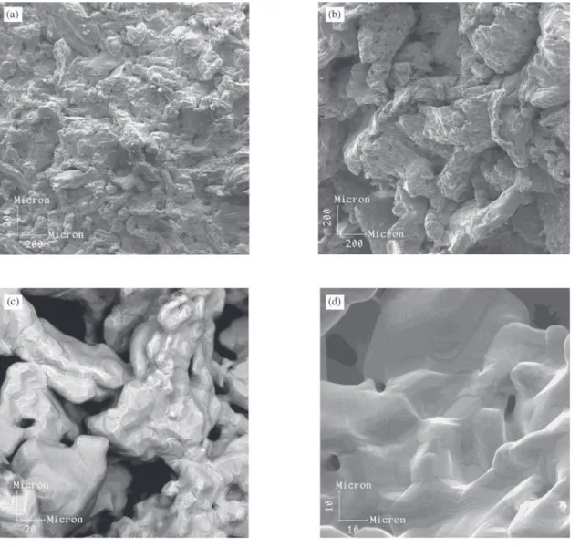
Figure 1 shows the appearance of the as sintered porous systems (substrate plus coating). From the SEM images of the specimens produced with greater porosity and, compacted with the lowest pressure, 200 MPa, the coatings exhibit open porosity (Figs. 2a - 2d). Interparticle bonds in Fig. 2c
indi-cate that sintering was in an advanced stage. The pore size Figure 1. As sintered type 3 porous system, compacted at 200 MPa.
distribution along the coating surface of all specimens was very broad, small pores along large pores appear, as illus-trated in Figs. 2c and 2d. The type 2 porous system (Figs. 2a and 2c) contains open pores with dimensions of approximately 20-50 µm while the coating made with larger particle size powder, type 4, has larger surface pores, of 100-300 µm (Fig. 2b). These results were expected, because it is known that larger particles sizes and inferior compaction pressures will produce larger pore sizes. The substitution of the com-pacting mould material for another one that allows lower pres-sures without damaging the surface of the compacted coat-ing would probably produce more porous structures.
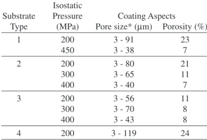
Table 2 shows the quantitative metallographic analysis for pore size range and percentual porosity. Higher
poros-ity fraction was achieved for the type 4 system, because it was produced with larger particle size powders and nar-rower size distribution. Maximum porosity fraction (% po-rosity) was obtained for the systems compacted at 200 MPa. Type 3 system shows inferior values of porosity for the same compaction pressures, compared with the other systems. This is probably because of the differences caused during manual mould filling technique. Homogeneity may be im-proved by changing filling mode from the manual to a tap instrument powder filling. Quantitative analyses of the po-rous size distribution along the coatings thickness and the porous percentage along the substrate/coating interface are in course, to give indication respectively of the coating ad-hesion and the porosity quantity that meet the requirements
Table 2. Isostatic pressures used and coating properties for the different substrate types.
Isostatic
Substrate Pressure Coating Aspects
Type (MPa) Pore size* (µm) Porosity (%)
1 200 3 - 91 23
450 3 - 38 7
2 200 3 - 80 21
300 3 - 65 11
400 3 - 40 7
3 200 3 - 56 11
300 3 - 70 8
400 3 - 43 8
4 200 3 - 119 24
* The size minimum “3 µm” was chosen to define the range (the majority of the pores were greater than this size in pixels).
for use as implants.
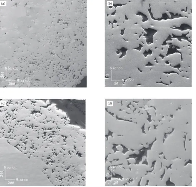
The measured thickness of the coatings produced was of approximately 1000 µm. SEM micrographs of a coating section for the systems 1 and 3, compacted at 200 MPa, are shown in Figs. 3a, 3b, 3c and 3d. It can be observed that the porosity is not interconnected, although in some regions (Fig. 3b) pore networks appears together with regions of closed porosity. The specimens compacted at pressures higher than 200 MPa presented only isolated pores. With respect to coating/substrate adhesion, type 1 and 2 speci-mens (Figs. 3a and 3b) presents smaller coating areas (or contact points) bonded with the substrate than the types 3 and 4 (Figs. 3c and 3d). This is possibly related to the substrate surface roughness and the fabrication process, as higher surface roughness implies better adhesion. The wrought substrates, types 1 and 2 exhibit lower roughness (Table 1), compared with the PM substrates, types 3 and 4, which are more porous on the surface.
While many researches4,6,9 make use of cast or wrought substrates, this work employs a wrought substrate and a substrate produced through powder metallurgy. The PM substrate presented the better coating adhesion, from a microstructure point of view, because of its surface poros-ity and higher roughness. With the continuporos-ity of this study, these results can be the basis to produce a functionally graded type PM system, with a degree of low porosity in the substrate to a highly porous surface in the coating.
5. Conclusion
The processing techniques used in this work proved to be suitable for producing titanium porous coatings and good adhesion with the substrate, from a microstructure analysis
point of view. Changes in mould filling approach for isostatic pressing is seen as necessary to optimize homogeneity of the porous coatings. As the pore size distribution along the coating was heterogeneous, the pore size distribution meas-urements are in course to give a more accurate statistical treatment. The porous structure requirements for surgical implant purposes were not met, indicating that it is neces-sary to reduce the sintering temperature up to a level were interparticle necks have just been formed. Also the substi-tution of the compacting mould material for another one that allows lower pressures would probably produce struc-tures with interconnected porosity and higher pore size and porosity.
Acknowledgments
The authors acknowledge CNPq and FUJB for finan-cial support, Prof. Renata A. Simão (LEMI/PEMM/COPPE) for profilometer measurements and Matheus T. Ibiapina for experimental assistance.
References
1. Recum A.F. Handbook of Biomaterials Evaluation, 2nd
ed., p. 30-240,1999.
2. Williams, D.F. Biocompatibility of Clinical Implant Ma-terials, Bocaraton, p. 17, 1981.
3. Pilliar R.M. Metal and Ceramic Biomaterial, Bocaraton, v. I, p. 80-105, 1994.
4. Story B.J.; Wagner W.R.; Gaisser D.M.; Cook S.D.; Rust-Dawicki A.M. The International Journal of Oral & Max-illofacial Implants, v. 13, n. 6, p.749-756, 1998. 5. Seah, K.H.W.; Thampuram R.; Teoh S.H. Corrosion
Sci-ence, v. 40, n. 4/5, p. 1841-1851, 1998.
6. Pilliar, R.M. Clinical Orthopaedics and Related Research, n. 176, June, p. 42-51, 1983.
7. Pilliar, R.M. Journal of Biomedical Materials Research, v. 21, n. A1, p.1, 1987.
8. Gearad, D.A; Koss D.A. Int. Journal Fatigue, v. 13, n. 4, p. 345, 1991.
9. Bobyn, J.D.; Pilliar, R.M.; Cameron H.U. et al.Clinical Orthopedics and Related Research, v. 150, p. 263, 1980. 10. Haddad, R.J.; Cook, S.D.; Thomas, K.A. The Journal of Bone and Joint Surgery, v. 69, n. 9, p. 1459-1465, 1987. 11. Deporter, D.A.; Todescan, R.; Nardini, K. Implant
Den-tistry, v. 8, n. 3, p. 233, 1999.
12. Henriques, V.A.R.; Bellinati, C.E.; Silva, C.R.M. Int. Conference On Advances in Materials and Processing Technologies – AMPT’99, August, p. 785-790, 1999. 13. Bellinati, C.E. Master Thesis, CTA/ITA/Brazil, p. 61,
1999.
14. Hamman, G. ASTM STP 953, p. 77, 1987.