*e-mail: [email protected]
Constant Load Creep Data in Air and Vacuum on
2.25Cr-1Mo Steel from 600 °C to 700 °C
Levi de Oliveira Bueno*, Vitor Luiz Sordi, Luiz Marino
Departamento de Engenharia de Materiais, DEMa,
Universidade Federal de São Carlos, UFSCar,
Rodovia Washington Luiz, km 235, 13565-905 São Carlos- SP
Received: July 19, 2004; Revised: October 28, 2005
Creep results on 2.25Cr-1Mo were obtained at 600 °C, 650 °C and 700 °C at ive stress levels, under constant load, in air and vacuum. Two chambers were specially developed for carrying out creep testing in controlled environment, with the possibility of accommodating inside them the load train, the extensometry system and the thermocouples. The creep machines used in this project present the advantage of allowing the performance of both constant load or constant stress creep testing, using interchangeable proiles. The preliminary set of constant load data reported here was analyzed according to the conventional methodology of creep data analysis, with the identiication of parameters of the Norton, Arrhenius, Monkman-Grant and some extrapolation relations involving stress, temperature, minimum creep rate and rupture time. The results indicate a strong effect of the oxidation phenomenon on the creep behavior of this steel. The data were consistent and meaningful so that the developed chambers can be considered to present good performance in the generation of creep data in vacuum.
Keywords:creep testing, oxidation, vacuum environment
1. Introduction
The study of the effect of oxidation on creep testing results is of particular importance for remaining life prediction. This is because current life estimates are based on standard ISO stress rupture data obtained from tests in air on small samples. Signiicant oxidation and metal loss occurs in long term tests specially on ferritic steels. The effect of oxidation on creep properties of type ½Cr-½Mo-¼V steel, for instance, was reported by Viswanathan1 considering speci-mens with four different diameters: 2.5, 5, 10 and 25 mm, tested at 675 °C. The specimen with the largest diameter was found to have a rupture life almost three times that of the smallest-diameter specimen. When the thin specimen was tested in argon, however, the effect of section size disappeared, indicating a purely environmental effect. Similar examples of the effect of oxidation on creep properties of this type of steel were reported by Cane et al.2 and Middleton et al.3. The signiicance of these observations is that the application of data obtained on small specimens in air to the assessment of thick section components will under-estimate their life. It is necessary therefore to correct the existing ISO data to account for oxidation. According to Middleton et al.3, thick section components at design stresses are estimated to have rupture lives two or three times those indicated by ISO tests. A better understanding of the effect of oxidation on creep testing results of ferritic steels therefore would signiicantly improve the accuracy of life prediction of many kinds of components, allowing for substantial life extension.
2. Methodology
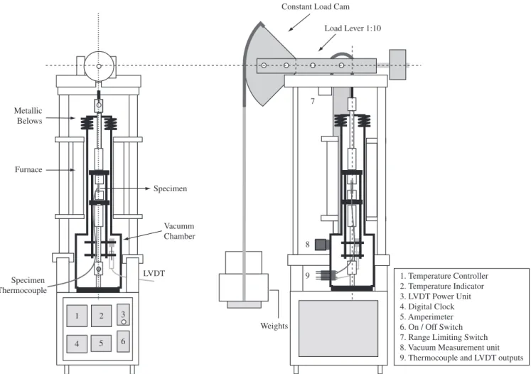
Two vacuum chambers were designed and built up to be used for mechanical tests at high temperatures under vacuum or any other kind of inert environment. The shape and dimensions of their compo-nents and details of appropriate systems for measuring temperature and strain were deined in terms of the structural details of testing machines already existing in the creep laboratory4,5. Figure 1 shows a general view of the apparatus used in this research. The interest-ing fact about these machines is that they enable the performance of
creep tests either at constant load or at constant stress by suitably interchanging mechanical cams with different proiles located in their deadweight levers. The constant load condition is attained by a circular proile cam whilst the constant stress condition by an Andrade-Chalmers cam.
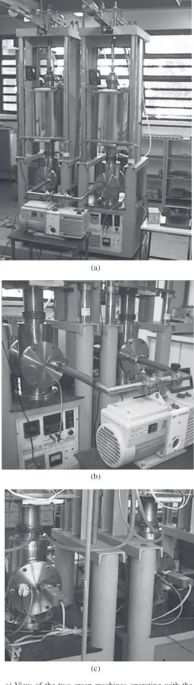
The chambers were designed to accommodate inside them all the components of the load train, of the extensometer and thermo-couples. The extensometers operate with LVDT transducers and the thermocouples were of the chromel-alumel type. The great beneit with these chambers is that they were designed to be rigidly ixed on the base of the creep machines, so that the lower pull rod is connected to an spherical joint ixed inside the instrument, as shown in Figure 1. Some types of environmental chambers are designed to be directly connected to the pull rods, being awkward to operate during prepa-ration of the creep test and prone to cause mechanical obstructions with the specimen load axis. With the present model most of these problems have been greatly minimized. Figure 2 presents photographs of a general view of two creep machines operating with the vacuum system with details of the front and back views of the chambers and the vacuum system components.
The chamber is divided in three main components:
• a lower component consisting of a section of a stainless steel tube (type 304) having about 200 mm diameter, 3 mm thickness and 300 mm length, with two lateral outlets with langes and vacuum seals (o-rings), as shown in Figures 2b and 2c. The front opening is used mainly for installation of the LVDT at the extensometer limbs. The disk covering this lange has the connections for the vacuum hose. The disk covering the back lange has the con-nections for the LVDT and thermocouples leads;
402 Bueno et al. Materials Research
• an upper component consisting of a metal bellows coupling having two langes with vacuum seals (Viton o-rings) for con-nection with the intermediate part and the upper tensile shaft, as shown in Figure 1 and Figure 2a.
A mechanical pump Edwards model CV-12 having 12 l/h capacity was used to provide vacuum to both chambers simultaneously. The level of vacuum was maintained close to 1 x 10⁻³ mbar and tempera-ture was maintained within ± 3 °C of the test temperatempera-ture during the tests. Better levels of vacuum pressure and temperature stability are programmed by the use of a diffusion pump and micro-processed P.I.D. temperature controllers in near future.
The measurements of specimen elongation and temperature were continuously monitored during the test with a Fluke data logger model Hydra – Series II-2635A. The system can store a large number of readings from each machine for subsequent processing. Typical scanning rates used in this work were: 1 reading/s, at the start of each test, 1 reading / minute or 1 reading / 10 minutes during most of the duration of the test, depending on creep deformation rates involved in each case. For each test a total of about 1000 to 3000 points were stored which were later iltered down to about 100 to 200 readings only. This number of points was considered suficient to deine well the shape of each creep curve.
In this work, the main objective was to check the performance of the chambers during creep testing in vacuum, considering a pre-liminary set of constant load creep tests on 2.25Cr-1Mo steel. Four creep machines were used: two for testing in air and two for testing
in vacuum. Constant stress tests using the same equipment, in air and in vacuum are also programmed for a next stage of this research.
The steel under study was supplied as a segment of plate with 2.54 mm thickness, in the normalized and tempered condition, having about 30 µm average grain size, consisting of about 60% tempered bainite and 40% pro-eutectoid ferrite. Details about its chemical composition, microstructure, etc. were given by Reis Sobrinho6. Figure 3 shows optical micro-graphs of the material in the as received condition.
The creep tests were carried out at 700 °C, 650 °C and 600 °C at the following stress levels: 51.7 MPa, 68.9 MPa, 86.2 MPa, 103.0 MPa and 120 MPa. Eighteen creep tests were completed for the present report, being nine in each environment (four tests at 700 °C, four at 650 °C and only one at 600 °C). Rupture times varied from 2.55 to 2347.57 hours. Other constant load tests are in progress at the lower temperature level of 600 °C, and more tests of this kind programmed at 500 °C and 550 °C, involving rupture times up to 5000 hours.
3. Results and Discussion
The performance of the two chambers was checked by continu-ously monitoring the main variables of the test: temperature, vacuum pressure and specimen elongation. The levels of stability of these measurements were considered satisfactory, as described in a previous article7. Table 1 presents a summary of the main data extracted from the creep tests and Figures 4a, 4b, 4c and 4d give some examples of
8
9 7
Specimen Thermocouple
Specimen
Vacumm Chamber
LVDT Furnace
Metallic Belows
Weights
Constant Load Cam
Load Lever 1:10
1. Temperature Controller 2. Temperature Indicator 3. LVDT Power Unit 4. Digital Clock 5. Amperimeter 6. On / Off Switch 7. Range Limiting Switch 8. Vacuum Measurement unit 9. Thermocouple and LVDT outputs
1 2 3
4 5 6
comparison between creep curves obtained in air and in vacuum for the different temperature and stress levels applied in the tests.
Figure 5 shows the variation of the rupture time with stress for the tests in air and in vacuum. For all the stress levels, the rupture times obtained in vacuum were systematically higher than the rupture times in air. The difference between these values becomes increas-ingly larger as the applied stress is decreased. This was an expected result since the effect of oxidation on the material is enhanced with the time of air exposition during the creep test.
The same result is shown in Figure 6 in double logarithmic form, i.e. in terms of the variation of creep strength [LOG (stress)] with creep life [LOG (rupture time)]. This is the kind of diagram that is normally adopted for presenting such data with engineering design purposes. It was observed that for 2.25Cr-1Mo steel, tested in the present experimental conditions, the rupture times for the tests car-ried in vacuum were around 1.5 to 3.2 times larger than the rupture times for the tests in air, as shown in Table 1.
The variation of the secondary (or minimum) creep rate with stress is shown in Figure 7. The results can be well expressed by the Norton law e.min = Aσn, both for vacuum and air test conditions. The stress exponents n presented an average value around 5, which is indicative of creep regime caused by dislocation movement controlled by recovery processes (dislocation climb, for instance). The result Figure 2. a) View of the two creep machines operating with the vacuum
system; b) front view; and c) back view of the two vacuum chambers on the creep machines.
(a)
(b)
(c)
404 Bueno et al. Materials Research
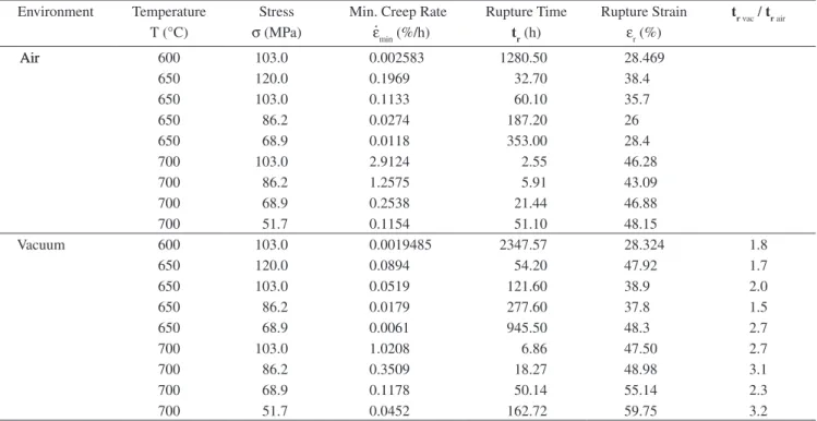
Table 1. 2.25Cr-1Mo creep data in air and vacuum.
Environment Temperature Stress Min. Creep Rate Rupture Time Rupture Strain tr vac / tr air
T (°C) σ (MPa) e.min (%/h) tr (h) er (%)
AirAir 600 103.0 0.002583 1280.50 28.469
650 120.0 0.1969 32.70 38.4
650 103.0 0.1133 60.10 35.7
650 86.2 0.0274 187.20 26
650 68.9 0.0118 353.00 28.4
700 103.0 2.9124 2.55 46.28
700 86.2 1.2575 5.91 43.09
700 68.9 0.2538 21.44 46.88
700 51.7 0.1154 51.10 48.15
Vacuum 600 103.0 0.0019485 2347.57 28.324 1.8
650 120.0 0.0894 54.20 47.92 1.7
650 103.0 0.0519 121.60 38.9 2.0
650 86.2 0.0179 277.60 37.8 1.5
650 68.9 0.0061 945.50 48.3 2.7
700 103.0 1.0208 6.86 47.50 2.7
700 86.2 0.3509 18.27 48.98 3.1
700 68.9 0.1178 50.14 55.14 2.3
700 51.7 0.0452 162.72 59.75 3.2
2.25 Cr-1Mo steel - 700 °C - 69 MPa
0 10 20 30 40 50 60
Time (h)
Strain (%)
60
40
20
0 air vacuum
(a)
2.25 Cr-1Mo steel - 700 °C - 52 MPa
0 30 60 90 120 150 180
Time (h)
Strain (%)
60
40
20
0 air vacuum
(b)
2.25 Cr-1Mo steel - 650 °C - 69 MPa
0 200 400 600 800 1000
Time (h)
Strain (%)
60
40
20
0 air vacuum
(c)
2.25 Cr-1Mo steel - 600 °C - 103 MPa
Time (h)
Strain (%)
air vacuum 60
40
20
0
0 500 1000 1500 2000 2500
(d)
1.7 1.8 1.9 2.0 2.1 2.2
LOG (stress, MPa) 3000
2500
2000
1500
1000
500
0
Rupture
T
ime (h)
600 °C vacuum 600 °C air
650 °C vacuum 650 °C air
700 °C vacuum 700 °C air
Figure 5. Variation of creep rupture time with stress, in air and in vacuum: for 700 °C and 650 °C, with schematic lines through the data at 600 °C.
Stressvs. Rupture Time
0 1 2 3 4
LOG (Rupture Time, h)
LOG
(s
tr
es
s,
M
P
a)
2.3
2.1
1.9
1.7
1.5
600 °C air
650 °C air 600 °C vacuum
650 °C vacuum
700 °C vacuum 700 °C air
Figure 6. Variation of creep strength with rupture time for 2.25Cr-1Mo steel, in air and vacuum.
seems consistent although the amount of data in each condition is still limited. More tests willbe necessary on a wider stress range to better distinguish material behavior from experimental scatter.
Figure 8 presents the variation of minimum creep rate with rupture time, as an attempt to verify the validity of the Monkman-Grant relation: emin. . trm = K. It is interesting to notice that there is no considerable difference between the two sets of results obtained in air and in vacuum. For the present range of stress and temperature
investigated both set of results can be expressed by the same linear regression line, with m = 1.084 and K = 8.247, taking e.min in (%/h) and tr in (h). This result is in good agreement with creep data obtained in air on 2.25 Cr-1Mo steel reported by Viswanathan1.
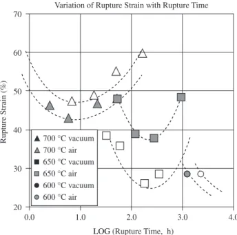
Figure 9 shows the variation of rupture strain (creep ductility) with rupture time. The trend of the data suggest the existence of a minimum value of rupture strain for each temperature level as the rupture time varies from the high stress to the low stress levels. This behavior is Figure 7. Variation of minimum creep rate with stress for 2.25Cr-1Mo steel, in air and vacuum.
Variation of Minimum Creep Rate with Stress
1.5 1.7 1.9 2.1 2.3
LOG(stress, MPa)
LOG
(Min Creep Rate, % h
-1) n = 4.5
n = 5.0 n = 5.3 n = 4.8 1.0
0.0
- 1.0
- 2.0
- 30
700 °C air 700 °C vacuum
650 °C air 650 °C vacuum
600 °C air 600 °C vacuum y = 4.854x - 9.343
y = 5.334x - 11.775 y = 4.964x - 11.336 y = 4.490x - 9.098
Minimum Creep Rate vs. with Rupture Time
0 1 2 3 4
LOG (Rupture Time, h)
LOG (Min Creep Rate, % h
-1) 1
0
- 1
- 2
- 3
- 4
o f
minxtr = 8.247
y = - 1.084x + 0.9163 R2 = 0.9945
600 °C vacuum 600 °C air 650 °C vacuum 650 °C air 700 °C vacuum
700 °C air 1.084
406 Bueno et al. Materials Research
0.0 1.0 2.0 3.0 4.0
LOG(Rupture Time, h) 70
60
50
40
30
20
700 °C vacuum 700 °C air 650 °C vacuum 650 °C air 600 °C vacuum 600 °C air
Variation of Rupture Strain with Rupture Time
Rupture Strain (%)
Figure 9. Variation of rupture strain with rupture time for 2.25Cr-1Mo steel, in air and vacuum.
also in agreement with the work reported by Glen8 on ½CrMo and 1CrMo steels which indicates that the lower the test temperature the longer the time to reach the minimum point in the curve and the lower the corresponding value in rupture strain.
In the present work there is some evidence that the creep ductility is always higher in vacuum than in air, but the time to reach these minimum values are identical in both situations on each temperature level.
A irst attempt was made to represent the rupture time data both in air and in vacuum by a parametric master curve, as recommended in literature1. There are several possibilities, which arises from the pattern of the iso-stress lines revealed by the LOG (rupture time) vs.
1/T or LOG (rupture time) vs. T diagrams. In this work, an attempt was made to express the data according to the Larson-Miller, Orr-Sherby-Dorn, Manson-Haferd and Manson-Succop methodologies. The irst two methods are derived from the LOG (tr) vs. 1/T plot and the other two from the LOG (tr) vs. T plot.
Figures 10a and 10b show the aspect of the iso-stress lines in the LOG (rupture time) vs. 1/T and LOG (rupture time) vs. T plots, respectively. The slopes and intercepts of the various regression lines are indicated in the graphs. Although the amount of data is still limited, the consistency is good and it is possible to derive the constants involved in each of the four methods mentioned above. The parameters were expressed by the following relations:
PLM = T [21.577 + LOG (tr)] POSD = LOG (tr) – 22082 / T PMH = -T / (LOG (tr) - 25.5931) PMS = LOG (tr) + 0.0251 . T for T in (K) and tr in (h).
It is important to mention, however, that all these constants may alter somewhat as more data is obtained and added to the analysis.
Figure 11 shows the different parameterization curves obtained in each case both for the data generated in air and in vacuum. It can be noticed that the results are approximately equivalent, with a slightly better it for the Manson-Succop and the Manson-Haferd analysis. It is interesting to notice also that the vacuum data shows less scatter than the air data in all these parameterization curves.
The important result is that all these parameterization analysis have shown a consistent displacement of the reference curve in vacuum to higher levels of stress in relation to the reference curve in air. Furthermore there is a clear indication that the trend for creep Figure 10. Variation of LOG (rupture time) with: a) inverse temperature; and b) temperature for 2.25Cr-1Mo steel, in air and vacuum.
Constants: Larson-Miller and Orr-Sherby-Dorn
1/T (K-1)
LOG
(Rupture
T
ime, h)
4.0
3.0
2.0
1.0
0.0
0.00100 0.00105 0.00110 0.00115 0.00120
y = 21511.68x - 21.25
y = 22912.59x - 23.11 y = 22910x - 21.845
y = 21225x - 20.552 y = 21851x - 21.126
y = 26955x - 26.932
103 MPa vacuum 103 MPa air
86.2 MPa vacuum 86.2 MPa air
68.9 MPa vacuum 68.9 MPa air
Constants: Manson-Haferd and Manson-Succop
850 900 950 1000
T (K)
LOG
(R
u
p
tu
re
T
im
e, h
)
y = - 0.0270x + 26.6930 y = - 0.0253x + 25.4888 y = - 0.0255x + 26.5210
y = - 0.0236x + 24.2572 y = - 0.0243x + 25.0053
y = - 0.0300x + 29.9756 4.0
3.0
2.0
1.0
0.0
103 MPa vacuum 103 MPa air
86.2 MPa vacuum 86.2 MPa air
68.9 MPa vacuum 68.9 MPa air
(a)
20500 21000 21500 22000 22500 23000 23500
Larson-Miller Parameter 2.3
2.1
1.9
1.7
1.5
LOG
(s
tre
ss
, M
P
a)
vacuum air y = - 1.916E-08x2 + 6.372E-04x - 2.770E+00 R2 = 9.976E-01
y = - 6.319E - 08x2 + 2.531E - 03x - 2.319E + 01
R2 = 9.671E - 01
(a)
- 23.0 - 22.5 - 22.0 - 21.5 - 21.0 - 20.5 - 20.0
Orr-Sherby-Dorn Parameter 2.3
2.1
1.9
1.7
1.5
LOG
(s
tre
ss
, M
P
a)
vacuum air y = - 2.433E - 02x2 + 1.245E + 00x - 1.358E + 01
R2 = 9.963E-01
y = - 5.803E - 02x2 + 2.751E + 00x - 3.046E + 01
R2 = 9.711E - 01
(b)
24.0 24.5 25.0 25.5 26.0 26.5 27.0
Manson-Succop Parameter 2.3
2.1
1.9
1.7
1.5
LOG
(s
tre
ss
, M
P
a) vacuum
air y = - 2.300E - 02x2 + 9.768E - 01x - 7.985E + 00
R2 = 9.982E-01
y = - 5.500E - 02x2 + 2.560E + 00x - 2.762E + 01
R2 = 9.747E-01
(d)
37 38 39 40 41 42
Manson-Haferd Parameter 2.3
2.1
1.9
1.7
1.5
LOG
(s
tre
ss
, M
P
a)
vacuum air y = - 7.248E - 03x2 + 4.592E - 01x - 4.842E + 00
R2 = 9.976E-01
y = - 1.749E - 02x2 + 1.241E + 00x - 1.981E + 0
R2 = 9.803E-01
(c)
Figure 11. Parameterization curves for 2.25Cr-1Mo steel in air and vacuum according to different methodologies: a) Larson-Miller; b) Orr-Sherby-Dorn; c) Manson-Haferd; and d) Manson-Succop.
strength drop with time and temperature is much lower for the tests carried out in vacuum compared to the tests in air. These param-eterization curves will be very useful to give a real idea of the creep strength of the material without the effect of oxidation during the creep tests. The data indicate that the effect of oxidation on creep results can be very drastic as time and temperature increases. Tak-ing rupture times of 1000 hours in air as reference, for instance, the Larson-Miller prediction indicates that the ratio trvac / trair assumes values of 2.2, 3.4 and 11.7 at 600, 650 and 700 °C respectively. For rupture times in air at 10,000 hours tr vac / tr air assumes values of: 2.2, 3.2 and 5.0 at 600, 650 and 700 °C respectively. For rupture times in air at 10,000 hours tr vac / trair can be as high as 3.0, 4.7 and 7.5 at 600, 650 and 700°C respectively. The 2.25Cr-1Mo steel is normally used at lower temperatures in the range from 550-600 °C in components which operate for about 300,000 hours so that tr vac / trair can be expected to vary from 2 to 3 in this situation, according to the estimation made by Middleton et al.3.
Figure 12 presents a comparison between the damage state of the specimens submitted to creep testing in air and in vacuum in the most aggressive oxidation condition in this work. The degree of
408 Bueno et al. Materials Research
damage caused by oxidation during creep can be drastic. Rings of the oxide layer formed during the tests are seen to break away from the gauge length of the specimen, depending on the temperature level and test duration. The specimen tested in vacuum was much less affected by oxidation.
A study on the kinetics of metal loss due to isothermal oxidation on 2.25Cr-1Mo steel was carried out using cylindrical samples with dimensions similar to specimens used in creep tests9. The metal thick-ness loss in the specimen diameter due to oxidation from 600-800 °C followed a parabolic law with time and a model was conceived for simulation of the interaction of creep and oxidation using the idea of the Stress Enhanced Factors due to the specimen cross sectional area reduction by oxidation, as presented in previous publication10.
The present work is under development, with a broad program of creep testing, considering other temperature levels and a wider range of stress in both test environments to conirm and improve the results reported in this article.
4. Concluding Remarks
The two recently developed environmental chambers for use in mechanical tests at high temperatures exhibited satisfactory perform-ance in the generation of creep data in vacuum. The preliminary set of results obtained in both conditions are consistent and meaningful so that the generation of more data of this kind at other temperatures and stress levels is viable.
Oxidation has a strong effect on creep curves in 2.25Cr-1Mo steel. The effect is noticed very early during the creep test, already in the minimum creep rate stage which in this kind of material happens at comparatively short times and low creep strain levels. The minimum creep rates in air were systematically higher than in vacuum, with the Norton exponent n being also slightly higher in air than in vacuum.
For the experimental conditions of stress and temperature chosen in this work, creep rupture times for tests in vacuum were about 1.5 to 3.2 times larger than rupture times for tests in vacuum. The creep rupture strength data could be parameterized according to four differ-ent methods. In all cases the reference curve in vacuum is displaced to higher stress levels than the reference curve in air, with a clear indication that the drop in creep strength with time is much lower for the tests carried out in vacuum than in air. The present data seem to conirm the prediction that creep lives of thick components with this steel operating in the range from 550-600 °C may be 2 to 3 times larger than the lives programmed on basis of laboratory creep data obtained on small specimens.
Analysis of both sets of results according to the Monkman-Grant relation indicates that a single straight line can be use to express the variation of LOG (minimum creep rate) with LOG (rupture time). This means that creep tests in air can be thought of as tests carried out at stress enhanced levels in relation to the applied stress levels used in vacuum. The effect of area reduction due to oxidation dur-ing creep can be considered in terms of a factor of stress increase which accelerates the minimum creep rate and reduces the rupture time maintaining the same Monkman-Grant constants (m and K) determined for tests in vacuum.
Based on these ideas, a broad programme of tests is under devel-opment involving other levels of stress and temperatures in the range from 500-700 °C, with rupture times going up to about 5,000 hours, to determine the pattern of variation of these stress enhancement factors with stress, temperature and time that make creep curves in air to be more accelerated than curves in vacuum for 2.25Cr-1Mo steel.
Acknowledgments
The authors acknowledge STM-Sistemas de Teste em Materiais Ltda for the loan of the vacuum chambers used in this project, Eng. José Cláudio Teixeira from CENPES/PETROBRAS for the support given during the conception of this research and F.A.S.Serra from REPLAN/PETROBRAS for supplying the material used in this research. Dr. Luiz Marino is grateful to CNPq/RHAE for a grant received during the experimental work.
References
1. Viswanathan R. Damage Mechanisms and Life Assessment of High-Tem-perature Components. 2nd ed. Ohio, USA: ASM International; 1993.
2. Cane BJ, Brear JM, Aplin PF. Condition assessment of high-temperature plant. in Evans RW, Wilshire B, editors. Proc. of the 3rd International
Conference on Creep and Fracture of Engineering Materials and Struc-tures; 1987 April 5-10; Swansea, UK. The Institute of Metals, London. 1987. p. 853-868.
3. Middlleton CJ, Timmins R, Townsend RD. The integrity of materials in high temperature components: performance and life assessement. Intl. Journal of Press.Vessel and Piping. 1996; 66(1):33-57.
4. Bueno LO. Máquinas-protótipos para ensaios de luência em metais a altas temperaturas. Parte 1: Detalhes de construção e montagem do equipamento. In Anais do II ETUAN -Encontro ABM de Tecnologia e Utilização dos Aços Nacionais. May 1987, Rio de Janeiro (RJ), Brazil. COPPE/UFRJ, Rio de Janeiro(RJ). 1987. p. 916-934.
5. Bueno, LO, Pigatin WL. Máquinas-protótipos para ensaios de luência em metais a altas temperaturas. Parte 2: Veriicação de desempenho do equipamento na geração de dados de luência. In Anais do II ETUAN -Encontro ABM de Tecnologia e Utilização dos Aços Nacionais. May 1987, Rio de Janeiro (RJ), Brazil. COPPE/UFRJ, Rio de Janeiro(RJ). 1987. p. 935-948.
6. Reis Sobrinho, J.F Correlações entre os Comportamentos de Tração a Quente e Fluência no Aço 2,25Cr-1Mo na Faixa de Temperatura de 500 a 700 °C.[D.Sc.thesis], São Carlos(SP), Brazil: Federal University of São Carlos; 2004.
7. Bueno LO, Marino L. Comportamento de luência do aço 2,25Cr-1Mo ensaiado ao ar e a vácuo, a 700 °C. In Anais do 57º Congresso Anual da ABM; 2002, July 22-25, São Paulo (SP), Brazil. 2002; p. 2046-2056. 8. Glen J. Some additional creep and rupture data on Mo, Cr-Mo and
Cr-Mo-V steels. Journal of the Iron and Steel Institute. 1955; 179:320-336.
9. Bueno LO, Marino L. High temperature oxidation behavior of 2¼Cr-1Mo steel in air- part 2: scale growth, metal loss kinetics and stress enhance-ment factors during creep testing. Transactions of the ASME / Journal of Pressure Vessel Technology. 2001; 123(1):97-104.
10. Bueno LO, Marino L, DeCarli CM. Preliminary results on possible effects of oxidation on creep curves of 2¼ Cr-1Mo steel tested in air. In Evans WJ, Evans RW, Bache MR, editors. Proceedings of the 1st.Intl.Conf.