IMPLEMENTATION
OF
SELF
DIAGNOSTIC
AND
INTELLIGENT
POWER
MANAGEMENT
PROTOCOLS
ON
WIRELESS
GAS
SENSOR
NODE
Dipanjan Bhattacharjee Sushabhan Choudhury Electronics and Communication Engineering School of Technology Sikkim Manipal Institute of Technology North Eastern Hill University
Majitar, Rangpo, East Sikkim, India Mawkynroh, Umshing, Shillong, India
1. Abstract
This paper presents implementation of self diagnostic, power management protocols and hardware design to enhance the hardware flexibility and sensing accuracy of sensor node. We have come with solutions for various design challenges faced on gas sensor. The embedded intelligent protocols over comes the problems of heater voltage dependency on gas sensors. Here we deal with sensors which are capable of detecting different part per million (ppm) of gases. The main aim of the work is to implement various intelligent protocols like auto error detection and correction, smart sensor triggering, sensor handover etc. We have designed hardware by which base station can remotely configure the operating modes of the node by sending various command signals wirelessly. Base station can come to know about health status of the sensor node by sending various enquiry signals. The two-way wireless communication is achieved by a pair of amplitude shift keying (ASK) transceiver; data is encoded before transmission and decoded after reception which provides high security to the data. The build in self-test and power management protocols make the node highly intelligent which enhance the life time of the node. All the signals are digitized and processed by a centralized programmable interface controller (PIC) based embedded platform and finally store in computer via serial port.
Keywords: power management protocols, gas sensor, intelligent protocols, smart sensor triggering, sensor handover, amplitude shift keying, programmable interface controller
2. Introduction
capability. Some of the nodes may participate in both sensing and routing. The routing includes both receiving and transmitting of data. Some nodes perform only sensing and transmit their data while some act as only routing nodes, especially where node power is limited. Yet some nodes may be in idle or in sleep mode to enhance the node lifetime. Sensor nodes perform play major role to sense the various environmental gases by the help of various gas sensors. The working principle of gas sensors is based on detection of gases with the sensing material in gas sensors. This material is a metal oxide, most typically SnO2. When a metal oxide crystal such as SnO2 is heated at a certain high temperature at around 400 degree Celsius in air, oxygen is adsorbed on the crystal surface which in turns changes the sensor resistance resulting in change of the sensor output voltage [3]. The power supplied to the heater coil is responsible for heating the sensor which leads to adsorption of oxygen. Thus the gas sensors are sensitive to the variation in heater voltage resulting in different adsorption and desorption of gases. The development of intelligent gas sensing systems recently focus due to increasing health related problem due to poor atmospheric condition and lack of intelligence of sensors. A number of research works have been published in last few years in the domain of integrated gas sensor and node. The conventional gas monitoring system such as gas chromatography (GC) limitations are long time, high expense and large installation space and also the measurements are conducted manually [4]. [5] Describes the development of smart sensor network for hazardous gas monitoring by using three types of gas sensors. Few studies have been found deal with practical development of sensor consists of multiple sensors with various power management protocols [6]. Sensorscope [7] and CitySense [8] are examples of large-scale wireless environmental monitoring systems. [9] Explore the possibilities of a practical WSN-based air pollution monitoring system and discussed various hardware and software issues. [10][11] Schemes focused on the implementation wireless sensor network for environment monitoring using chemical sensors. As previous studied did not detail considerations related to issues such as self-diagnosis protocols, hardware flexibility and intelligent power management. Our work provides more intelligence to the sensor node which enhances the sensing efficiency and lifetime of the sensor node.
3. Problem Definition
The main obstacles for developing gas sensor based wireless sensor nodes are limited onboard processing capability and limited power source. The sensors used in the work are namely TGS-813 and TGS-2600 is SnO2 based gas sensors. They have different activation time known as start up time and hence both the sensors are not activated at same time while triggered at same time, it is not synchronized, it causes unnecessary power consumption because until both the sensors will not be ready for sensing. This requires an intelligent protocol so that the power consumption is minimal. The sensor consists of a heater coil so that SnO2 within the sensor is heated to a temperature of about 400 degrees for the purpose of adsorption of gases. At fixed PPM of gas concentration the output of the gas sensor changes with a change in heater supply voltage. The gas sensor has a high heater voltage dependency so a constant heater voltage needs to be supplied to the gas sensor. This heater voltage may change due to low flow of current in the heater coil or prolonged use of battery, so we need a constant voltage to be supplied. If this is not done the sensor output will vary erratically which produce erroneous result. Another major challenge is the scaling of gas sensor. The TGS-2600 has a detection range of (5-100) PPM level while TGS-813 has a good detection range of (100-10000) PPM. The TGS-2600 has a high resolution in the range of (5-100) PPM level, while TGS-813 has a high resolution in between (100-10000) PPM level. Therefore, to obtain high resolution along with high detection range both sensors need to be smartly switched depending on the environmental gas concentrations. Another challenge is that the initial response of the gas sensor is non-linear in the beginning regardless of the presence of the gas in the atmosphere. The resistance drops sharply for the first few seconds after energizing, regardless of the presence of gases, and then reaches a stable level according to the ambient atmosphere which results in a phenomenon called initial action. This calls for a smart protocol for the consideration of this behavior of the sensor since this may raise an alarm regardless of gas. The gas levels at a certain time will change drastically or remain same for a fixed period of time. For high variations in the values the recordings remain in cognizance with the pre-defined sampling rate. But for same values of a sample for a fixed time, the challenge is to conserve power. The values are more or less same, without compromising the measurement efficiency of sensing. The 80% node power is used for wireless communication. So for enhancing the node lifetime smart power saving protocols are essential. To avoid data collisions among the nodes real time synchronization is must.
4. Proposed Solution
hardware complexity. The gas sensors especially SnO2 based gas sensors have different start-up time. Start-up time is the time taken by any gas sensor to stabilize the output irrespective of gas concentration. Thus there is a requirement for intelligent sensor triggering to synchronize the sensors to start functioning at same time allowing conserving vital power in the sensor node. If sensor1 starts its operation after time t1 and sensor2 starts the operations after time t2 and t1>t2, we need to trigger sensor2 after time (t1 – t2) so that both sensors operate at same time. This time is called settling time. Thus we use an intelligent protocol which triggers the sensors so that both the sensors start their operations at the same time. The heater coil needs to be supplied with constant supply voltage since the outputs of SnO2 based gas sensors have a high heater voltage dependency. We have designed an intelligent protocol (named auto error detection and correction) which monitors the supplied heater voltage so that the sensor voltage remains unaltered due to the change in heater voltage. Depending on the heater voltage we add or subtract an offset voltage which is obtained from scaling factor of heater voltage dependency curve to get the desired corrected constant sensor voltage. We scale both gas sensors so as to get a better resolution using an intelligent protocol which switches between the gas sensors automatically depending on gas concentration level in the environment. According to PPM level suitable sensor is switched, resulting in a better resolution in gas sensing application. We also developed a protocol which can tune the sampling rate depending on the previous samples information, it also define an intelligent sleep time period for the node to minimize the power level without compromising the sensing efficiency.
4.1. Experimental setup and hardware prototype
Extensive experiments have been carried out to validate the proposed solution. The (Fig: 1) is the block diagram of experimental sensor node and (Fig: 2) describes the hardware prototype of sensor node along with display unit. Here we deal with two gas sensors namely TGS 2600 and TGS 813. Variable power supply used to supply a range of voltages to the heater coil and sensor material, the sensor switching (on and off) are done by relay switches which are controlled by the centralized PIC 18F450 microcontroller. All the supplied powers to the sensors are fed back to the microcontroller using internal analog to digital converter (ADC) to monitor the supplied power and execute the intelligent protocols. The node powers have been supplied using a multichannel variable power supply. The node consists of two gas sensors TGS 2600 and TGS 813 these sensors requires heater voltage 5V which is applied to the integrated heater in order to maintain the sensing element at a specific temperature which is optimal for sensing. The maximum circuit voltage for TGS 2600 and TGS 813 are 5V and 24V respectively. Therefore a DC to DC converter is used to provide desired circuit voltage.
Fig1: Wireless sensor node experimental setup
are multiplexed. The sampling rate are not fixed it varies automatically depending on the situations. The sensed data are encoded using HT 640 encoder integrated circuit before transmission, which forms an 18bit data frame consists of 8bit data and 10bit address which carries node identification and data information, simultaneously the received command from base station is decoded by HT648l decoder. The node is equipped with a 433 MHz ASK transmitter and a 315 MHz receiver for wireless communication which enable node to perform two way communication, these make unicast communication with data security. The 10bit address select the unique identity to the node and base station, two different frequencies are used to avoid any jamming problem and also enables full duplex communication. The node has free space wireless communication range of 200meters. The sensor node consumes 20mA current in sleep mode approximately 185mA in active mode but the exactly power consumption depends on several parameter like no of sensor on, sampling time, power level etc. The internal electrically erasable programmable read only memory (EEPROM) stores the transducer electronic data sheet (TEDS) information. The output of processed signal is displayed in a liquid crystal display (LCD) where sampling rate, sensor status and gas concentration information can be obtained. The data are transmitted to computer using RS 232 serial communication port for statistical analysis. We have used MPLAB IDE for developing the software. The supply is given to heater coil through a high power switching transistor so that the microcontroller can turn on or off the heater supply depending on the requirement decided by the intelligent algorithms.
4.2. Self diagnostic protocols
The gas sensors which we have used are sno2 based. The sensor nodes are basically powered by rechargeable batteries which limit their life time after which the batteries have to be recharged, as the battery discharges potential drop across the battery slowly decreases. On experimenting we observed that the potential drop has a severe effect on sensitivity of sensors (fig: 3). We experimented on TGS 813 to find out the dependency of output voltage on the heater voltage due to the fact that as the battery discharges the potential drop across the heater coil of TGS 2600 decreases. We therefore kept the gas concentration, temperature and humidity inside the test gas chamber constant and varied the heater voltage. The observations are shown in the (fig: 4).
Fig2: Wireless sensor node hardware prototype with display unit
The heater voltage dependency graph shows us how change in heater voltage affect the sensor output voltage when all other parameters are experimentally kept constant. Even a small change in the potential drop across heater coil alters the sensor output drastically. We therefore developed an intelligent protocol which is capable of monitoring the heater voltage continuously and also adding a value called the offset value to the sensor output so that the sensor output becomes reliable irrespective of changes in heater supply voltage. We also observe that the ratio of sensor of sensor output for different gas concentrations does not depend upon heater voltage, so we can correct the output. We therefore construct a look up table which is obtained by extensive experimentation on varying heater voltage each time for a different ppm of gas. The node memory is used to store this look up table. The microcontroller has a 10chennel 10bit ADC in it; this is used to measure the voltage continuously. Each time the potential drop across the heater changes an offset value is fetched from the look up table which is then added or subtracted from the output received from sensor depending upon the actual scenario, this process ensures accurate and reliable result. From (fig: 4) we obtain a scaling factor which is used for scaling the sensor output voltage. This graph shows us the different scaling factors for different values of heater voltage. Each time the microcontroller encounters a fall in heater voltage it fetches the corresponding scaling factor and accordingly an offset value is added to output value. The (Fig: 5) describes deviation between theoretical correction and experimental corrected results for various heater voltages which are approximately similar.
PC interface
Fig 3: Heater voltage dependency curve Fig 4: Scaling factor for different heater voltage
Fig5: Deviation between Experimental and Theoretical value
4.3. Intelligent power management protocols
.
Fig 6: Standby and initial response of TGS 2600 and TGS 813
4.3.1 Supervisory mode:-
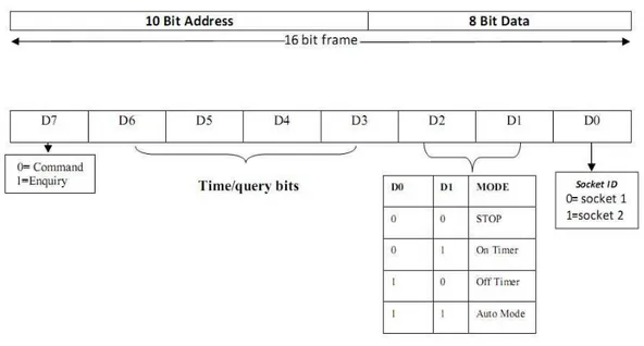
In the supervisory mode the base station can configure the node wirelessly as well as it can receive various query response from the node, in this mode base station can alter the sampling time, sleep time, also it can send query signals to know physical status of the node node like power remaining, current memory status etc. The commands are given to the node from the base station. The base station interacts with node by a of 18 bit information, each node has a unique 10 bit address, the first 10 bits determine the address of the remote node. The next 8 bits are data bits. (fig:7) 18 bit data frame used for supervisory mode of communication. The node
Fig 7: 18 bit data frame for supervisory mode of communication
operation related to TGS 2600 and if it is high then it is for TGS 813. The bitsD2 and D1 determine the power management modes, there are three power management mode and one for mode switching, it can be operated either on timer mode in which the sensor will automatically on after a certain delay or in off timer mode where initially sensor will be in on state and after predefined time particular sensor will be switched off depending on socket identification bit D0, the delay time is configured by data bits D3 to D6 determine the time function of each bit (5 min/10min)per bit which ensure time scale of 75minutes or 150 minutes. The bit D7 is called command/inquery bit when it is high it initiates a command pulse pulse and performs a operation on node but in query mode D7=1 it doesnot performs any operation on the node by receiving any query pulse node replay the base station with desired information.
4.3.2 Auto mode:-
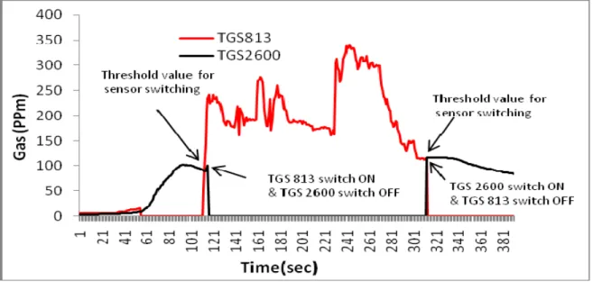
The sensor node can be switched to auto mode by sending a command signal with bit D1=D2=1, in this mode node uses embedded intelligent protocol for power management. In supervisory mode the user decides to activate one of the sensors and assign a sampling rate. In auto mode, the sensor that is to be activated is decided by the node itself depending on the concentration of the gas in the surrounding environment and sampling rate is decided on the basis of power remaining and results of cross correlation of the individual sensor. The decision making protocol to switch the sensors is primarily based on the concentration of the gas in the atmosphere. There may be two types of condition in the variation of the concentration of gas: either the concentration of the gas will be gradually increasing /decreasing or fluctuate. The detection range of TGS-2600 is nearly (1-200) ppm while that of TGS-813 is (100-10000) ppm approximately, a single sensor cannot detect a large scale of gas, the embedded protocol set two threshold point for the sensors, when gas concentration about to reach the highest detection range of TGS 2600 microcontroller detect the threshold and automatically trigger the TGS 813 and turn off TGS 2600 which have two advantages first higher ppm gas can be sensed by the TGS 813 and power consumption is reduced by turning off the TGS 2600. In reverse case when gas concentration starts decreasing and riches the lower threshold of TGS 813 it turns on TGS 2600 and TGS 813 will be turned off. Fig. 8 shows the gradual variation in the concentration of the gas in the environment with time and the operation performs by the embedded intelligent protocols it also describes how sensor handover is done autonomously when gas concentration goes beyond the detection range of individual sensors.
Fig 8: implementation of intelligent sensor handover
5. Conclusions
approx. all the design challenges with our proposed solutions. We see that it helps us to overcome many difficulties on vital areas of gas sensors. If these are implemented on our work area as shown in practical system, will help us obtain a better enhanced sensor with low cost, long life, good sensitivity, accuracy, reliability, intelligence and high data security. The need of the low power consumption is made under maximum control with the designs implemented. By incorporating these intelligent protocols we have achieved high accuracy, low power consumption and high detection range without increasing designing cost of wireless sensor node.
Acknowledgements
This work has been carried out in electronics & communication department, Sikkim Manipal Institute of Technology (SMIT), and supported by north eastern hill university (NEHU). Authors wish to thank both the University for providing all laboratory and equipments support for the research work.
References
[1] Randy Frank, Understanding Smart Sensors Second Edition, ARTECH HOUSE, INC. 685, Canton Street, Norwood, MA 02062.UK [2] Feng Zhao, Leonidas j. Guibas, Wireless Sensor Networks, Morgan Kaufmann Publishers, 340 pine Street SanFrancisco, CA
94104-3205.
[3] www.figarosensor.com
[4] Synergist Buyer’s Guide. Indor Air Quality. Available online:http://www.aiha.org/theynergist/html/bg/iaq.htm.
[5] Dipanjan bhattacharjee,Sushaban choudhury, Ajay kumar”Wireless intelligent smart sensor node for hazardous gas monitoring” international journal of Computer Science and Information Technology (IJCSIT), Vol 3, No 1, Pp. 53-57. june 2010.
[6] Dipanjan bhattacharjee, Akash kumar, Sourabh Kumar, Sushabhan choudhury, “ Design and Development of Wireless sensor Node” International Journal of Computer science and Engineering (IJCSE), Vol 02, No. 07,2010, 2431-2438
[7] Barrenetxea, G.; Ingelrest, F.; Schaefer, G.; Vetterli, M.; Couach, O.; Parlange, M. SensorScope: Out-of-the-Box Environmental Monitoring. In Proceedings of the 7th International Conference on Information Processing in Sensor Networks, St. Louis, MO, USA; IEEE Computer Society: St. Louis, MO, USA, 2008.
[8] Murty, R.N.; Mainland, G.; Rose, I.; Choudhury, A.R.; Gosain, A.; Bers, J.; Welsh, M. CitySense: An Urban-Scale Wireless Sensor Network and Testbed. In Proceedings of the 8th IEEE Conference on Technologies for Homeland Security, Waltham, MA, USA; IEEE Computer Society: Waltham, MA, USA, 2008.
[9] Sukwon Choi, Nakyoung Kim, Hojung Cha, Rhan Ha, “Micro Sensor Node Air pollutant Monitoring: Hardware and Software Issues” Sensors 2009,mdpi, 7970-7987.
[10] Murty, R.N.; Mainland, G.; Rose, I.; Choudhury, A.R.; Gosain, A.; Bers, J.; Welsh, M. CitySense: An Urban-Scale Wireless Sensor Network and Testbed. In Proceedings of the 8th IEEE Conference on Technologies for Homeland Security, Waltham, MA, USA; IEEE Computer Society: Waltham, MA, USA, 2008.
[11] Jer Hayes, Stephen Beirne, King-Tong Lau, Diamond “Evaluation of a low cost Wireless Chemical Sensor Network for Environmental Monitoring” International Conference IEEE SENSORS 2008 .
[12] Crossbow Technology Company: San Jose, CA, USA; Available online: http://www.xbow.com/, accessed March 10, 2009.
[13] Honicky, R.; Brewer, E.A.; Paulos, E.; White, R. N-smarts: networked suite of mobile atmospheric real-time sensors. In Proceedings of the 2nd
[14] ACM SIGCOMM Workshop on Networked Systems for Developing Regions, Seattle, WA, USA; ACM: Seattle, WA, USA, 2008. [15] Song, G.; Zhou, Y.; Ding, F.; Song, A. A mobile sensor network system for monitoring of unfriendly environments. Sensors 2008, 8,
7259-7274.
[16] Rerkrai, K.; Jardak, C.; Kovacevic, A.; Riihijärvi, J.; Mähönen, P. Demo abstract: Survivable and scalableWSN solution for environmental monitoring in harsh conditions. In proceedings of 6th European conference on wireless sensor network, Cork, Ireland,
U.K, february 11-13, 2009.
[17] Scalable WSN solution for environmental monitoring in harsh conditions. In Proceedings of 6th European Conference on Wireless Sensor Networks, Cork, Ireland, UK, February 11-13, 2009.
[18] Randy Frank, Understanding Smart Sensors Second Edition, ARTECH HOUSE, INC. 685, Canton Street, Norwood, MA 02062.UK [19] Roderick Shepherd, Stephen Beirne, King Tong Lau, Brian Corcoran,Dermot Diamond, Monitoring chemical plumes in an
environmental sensing chamber with a wireless chemical sensor network, Sensors and Actuators B: ChemicalVolume 121, Issue 1, Special Issue: 25th Anniversary of Sensors and Actuators B: Chemical, 30 January 2007,