ISSN 1941-7020
© 2008 Science Publications
Corresponding Author: Seyed Abbas Taher, Department of Electrical Engineering, University of Kashan, km 6 Ravand Road, Kashan, Iran Tel: +98-9131614352 Fax: +98-3615559930
45
Comparison of Different Control Strategies in GA-Based Optimized
UPFC Controller in Electric Power Systems
Seyed Abbas Taher, Reza Hematti and Majid Nemati
Department of Electrical Engineering, University of Kashan, Kashan, Iran
Abstract: This study presents a study of the application of a Unified Power Flow Controller (UPFC) to control power transmission, generator terminals voltage and better damping of Low Frequency Oscillation (LFO) in Single-Machine Infinite-Bus (SMIB) power system. The UPFC integrates properties of both shunt and series compensations and can effectively alter power system parameters in a way that increases power transfer capability and stabilizes system. In practice systems use simple Proportional Integral (PI) controllers for control of UPFC. However, since the PI control parameters are usually tuned based on classical or trial-and-error approaches, they are incapable of obtaining a good dynamic performance for a wide range of operation conditions. To address this problem, in this research an optimization approach, based on the Genetic Algorithms (GA) method is proposed for the design of UPFC controllers (power-flow controller, DC-voltage regulator and generator terminals voltage controller) and also supplementary damping controller for increase damping of power system oscillations is developed. A SMIB power system installed with a UPFC is considered for case study. Several linear time-domain simulation tests visibly show the effectiveness and validity of proposed method in control of power transmission, terminal voltage of generator and enhance of LFO damping.
Key words: Flexible AC transmission systems, power system oscillations, unified power flow controller, genetic algorithms
INTRODUCTION
The Flexible AC Transmission Systems (FACTS) based on power electronics offer an opportunity to enhance controllability, stability and power transfer capability of AC transmission systems[1]. The UPFC, which is the most versatile FACTS device, has the capabilities of controlling power flow in the transmission line, improving the transient stability, mitigating system oscillation and providing voltage support[2-4].
PID is the most commonly used control algorithm in the process industry. Also, this technique is used to control the FACTS devices[5]. However, the nonlinear nature as well as the uncertainties that exist in the system make it difficult to design an effective controller for the FACTS that guarantees fast and stable regulation under all operating conditions. A major source of difficulty is that open-loop plant may change. In particular, inaccuracy in plant may cause problems because the plant is part of the feedback loop. To deal with such a problem, instead of using a single model plant, an uncertain model should be considered. This problem has led to the study of applying adaptive
controllers for instance[6-7], nonlinear controllers for instance[8] in the power system stability control. Also, during past decade, the H∞ optimal robust control
design has received increasing attention in power systems. Most of the above methods have been applied in power systems and some of these efforts have contributed to the design of supplementary control for SVC using mixed sensitivity[9], applying µ-synthesis for SVC in order to voltage control design[10] and supplementary control design for SVC and STATCOM[11].
optimized controllers based on GA guarantee the good performance for various conditions and disturbances.
MATERIALS AND METHODS
Figure 1 shows a SMIB power system with UPFC installed[1]. The UPFC is installed in one of the two parallel transmission lines.
This configuration, comprising two parallel transmission lines, permits the control of real and reactive power flow through a line. The static excitation system, model type IEEE-ST1A, has been considered. The UPFC is assumed to be based on Pulse Width Modulation (PWM) converters.
This research focuses on optimal tuning of different controllers for UPFC using GA. The aim of the optimization is to search for the optimum controller parameter setting that maximize the minimum damping ratio of the system.
Dynamic model of study system:
Linear dynamic model: A linear dynamic model is obtained by linearising the non-linear model around an operating condition. The linearised model is given below[12]:
(0 e )
/ /
q q fd do
A
fd fd
A A
/
dc 7 8 q 9 dc
ce E cδe E cb B cδb B
∆δ ∆
∆ω ∆P D∆ω /M
∆E ( ∆E ∆E )/T
1 K
∆E ∆E ∆V
T T
∆v K ∆δ K∆E K∆v K ∆m K ∆δ K ∆m K ∆δ
=
= − −
= − +
= − −
= + − +
+ + +
&
& &
&
& ω ω
(1)
Figure 2 shows the transfer function model of the system including UPFC. The model has 28 constants denoted by K. These constants are functions of the system parameters and the initial operating condition. The control vector u is defined as follows:
T B B E
E ∆δ ∆m ∆δ ]
∆m [
u= (2)
Where:
∆mB: Deviation in pulse width modulation index mB of
series inverter. By controlling mB, the magnitude
of series- injected voltage can be controlled
∆δB: Deviation in phase angle of injected voltage
∆mE: Deviation in pulse width modulation index mE of
shunt inverter. By controlling mE, the output
voltage of the shunt converter is controlled
∆δE: Deviation in phase angle of the shunt inverter
voltage
Fig. 1: A SMIB power system installed with an UPFC in one of the lines
D
MS 1 + S
W0
K1
K4 K5
K6
K2
K7
K8
STa
ka
+
1 /
1
STdo
K3+
Kpd
Kvd
Kvu
Kqd
Kqu
Kcu
Kp
1
K9
S +
Vref
∆ − −
− −
+
+ +
+ +
+ +
− +
+ −
− −
U
+
Pm
∆
/
Eq
∆
Vd
∆
∆ Pe
The series and shunt converters are controlled in a coordinated manner to ensure that the real power output of the shunt converter is equal to the power input to the series converter. The fact that the DC-voltage remains constant ensures that this equality is maintained.
It may be noted that Kpu, Kqu, Kvu and Kcu in Fig. 2
are the row vectors and u is as follow:
T B B E
E ∆δ ∆m ∆δ ]
∆m [ u=
Dynamic model in state-space form: The dynamic model of the system in state-space from transfer-function model is as (3).
0 pd 1 2 qd 4 3 / / / / / / q q
do do do do
A 5 A 6 A vd
fd fd
A A A A dc
dc
7 8 9
0 w 0 0 0
∆δ K ∆δ
K K
0 0
∆w M M M ∆w
K
K K 1
0
∆E ∆E
T T T T
K K K K 1 K K
∆E ∆E
0
T T T T ∆v
∆v
K 0 K 0 K
0 • • • • • − − − − − − = × − − − − − +
pe pδe pb pδb
E
qe qδe qb qδb E
/ / / /
do do do do B
A vc A vδe A vb A vδb B
A A A A
cδe cb cδb
0 0 0
K K K K
∆m
M M M M
K K K K ∆δ
T T T T ∆m
K K K K K K K K ∆δ
T T T T
Kce K K K
− − − − − − − − × − − − − (3)
UPFC Controllers: The UPFC control system comprises four controllers:
• Power flow controller
• DC-voltage regulator controller
• Generator terminals voltage controller
• Power system oscillation-damping controller
Power flow, DC-voltage regulator and generator terminals voltage controllers: The UPFC is installed in one of the two lines of the SMIB system. Figure 3 shows the structure of the power flow controller. The power flow controller regulates the power flow on this line. The real power output of the shunt converter must be equal to the real power input of the series converter or vice versa. In order to maintain the power balance between the two converters, a DC-voltage regulator is incorporated. DC-voltage is regulated by modulating the phase angle of the shunt converter voltage. Figure 4 shows the structure of the DC-voltage regulator. Figure 5 shows the structure of the generator terminals
Pe2
Pe2 ref pi mB
pp K K
S
+
Fig. 3: Power flow controller
VDC
VD Cref dp pi δE
K K
S
+
Fig. 4: DC-voltage regulator
Vtref Vt mE vi vp K K S +
Fig. 5: Generator terminals voltage controller
∆mΒ
KD W
W
sT 1 sT+
1 2 1 sT 1 sT + + δω
Fig. 6: Structure of damping controller
voltage controller. The generator terminals voltage controller regulates the voltage of generator terminals after occur a disturbance in system.
Power system oscillations-damping controller: A damping controller is provided to improve the damping of power system oscillations. This controller may be considered as a lead-lag compensator[13-14] or a fuzzy controller block[15]. However an electrical torque in phase with the speed deviation is to be produced in order to improve the damping of the system oscillation. The transfer function block diagram of the damping controller is shown in Fig. 6.
Table 1: Eigen-values of the closed-loop system without damping controller
-19.2516 0.0308±2.8557i -0.6695±0.512i
Table 2: Eigen-values of the closed-loop system with damping
controller
-19.3328, -16.4275, -2.8609
-0.9251±0.9653i
-0.8814, -0.1067
The constants of the transfer-function model of Fig. 2, computed for the nominal operating condition.
For this operating condition, the eigen-values of the system are obtained (Table 1) using the state-space form transfer-function model of system in (5) and it is clearly seen that the system is unstable. Thus the system need to supplementary damping controller for stability.
Design of damping controller for stability: The damping controllers are designed to produce an electrical torque in phase with the speed deviation according to phase compensation method. The four control parameters of the UPFC (mB, mE, δB and δE) can
be modulated in order to produce the damping torque. In this study mB is modulated in order to damping
controller design. The speed deviation δω is considered as the input to the damping controllers. The structure of damping controller is shown in Fig. 6. It consists of gain, signal washout and phase compensator blocks. The parameters of the damping controller are obtained using the phase compensation technique. The detailed step-by-step procedure for computing the parameters of the damping controllers using phase compensation technique is presented in[13-14]. Damping controller mB
was designed and obtained as follows (wash-out block is considered). Damping controller of power flow controller with damping ratio of 0.5 is:
(
)
(
) (
)
536.0145 s s 3.656 Damping Controller
s 0.1 s 4.5 + =
+ + (4)
After employ this damping controller to system, the eigen-values of the system with damping controller are obtained (Table 2) and it is clearly seen that the system is stable.
After stability of system, the next step is design of internal UPFC controllers (power-flow controller, DC-voltage regulator and generator terminals DC-voltage controller) using GA method. Before beginning of design process, it is necessary to introduction with GA. In the next section a brief description about GA optimization is developed.
Genetic algorithm: Genetic Algorithms (GA) are global search techniques, based on the operations observed in natural selection and genetics[16]. They operate on a population of current approximations- the individuals- initially drawn at random, from which improvement is sought. Individuals are encoded as strings (chromosomes) constructed over some Particular alphabet, e.g., the binary alphabet {0.1}, so that chromosomes values are uniquely mapped onto the decision variable domain. Once the decision variable domain representation of the current population is calculated, individual performance is assumed according to the objective function which characterizes the problem to be solved. It is also possible to use the variable parameters directly to represent the chromosomes in the GA solution. At the reproduction stage, a fitness value is derived from the raw individual performance measure given by the objective function and used to bias the selection process. Highly fit individuals will have increasing opportunities to pass on genetically important material to successive generations. In this way, the GA search from many points in the search space at once and yet continually narrow the focus of the search to the areas of the observed best performance.
The selected individuals are then modified through the application of genetic operators. In order to obtain the next generation genetic operators manipulate the characters (genes) that constitute the chromosomes directly, following the assumption that certain genes code, on average, for fitter individuals than other genes. Genetic operators can be divided into three main categories[16]: Reproduction, crossover and mutation.
• Reproduction: selects the fittest individuals in the current population to be used in generating the next population
• Cross-over: Causes pairs, or larger groups of individuals to exchange genetic information with one another
• Mutation: causes individual genetic representations to be changed according to some probabilistic rule
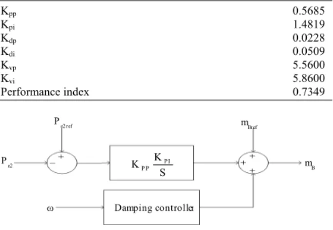
GA Based UPFC Controllers: In this section internal UPFC controller are tuned by GA. The goals are control of power transmission of line 2, control of DC voltage of UPFC and control of generator terminals voltage. Also stability of system and good damping oscillations is necessary in the process of control. The structures of these controllers are show in Fig. 3-5. Where Kpp and Kpi are the parameters of power flow controller, Kdp and Kdi are the parameters of DC voltage regulator and Kvp and Kvi are the parameters of generator terminals voltage controller.
In this study, the optimum values of these six parameters (Kpp, Kpi, Kdp, Kdi, Kvp, Kvi) which minimize an array of different performance indices are easily and accurately computed using a GA. In a typical run of the GA, an initial population is randomly generated. This initial population is referred to as the 0th generation. Each individual in the initial population has an associated performance index value. Using the performance index information, the GA then produces a new population. The application of a GA involves repetitively performing two steps:
• The calculation of the performance index for each of the individuals in the current population. To do this, the system must be simulated to obtain the value of the performance index. The GA then produces the nest generation of individuals using the reproduction crossover and mutation operators
• These two steps are repeated from generation to generation until the population has converged, producing the optimum parameters
The performance index considered in this study is of the form:
e2 DC
0 0 0
Per _ Ind t dt t P dt t V dt
∞ ∞ ∞
= α
∫
∆ω +β ∆∫
+ γ∫
∆ (5)Where ∆ω is speed deviation and ∆VDC is
deviation of DC voltage and ∆Pe2 is deviation of power transmission of line 2. To compute the optimum parameter values, a 0.1 step change in mechanical torque (∆Tm) is assumed and the performance index is minimized using a GA. In the next section, the optimum values of the parameters Kpp, Kpi, Kdp, Kdi, Kvp and Kvi, resulting from minimizing the ITAE performance index are presented. This case for performance index was considered.
Case 1: α = β = γ = 1 (speed deviations, DC voltage deviation and power flow deviation are equally penalized).
Table 3: Optimum value of parameters of internal UPFC controllers
Kpp 0.5685
Kpi 1.4819
Kdp 0.0228
Kdi 0.0509
Kvp 5.5600
Kvi 5.8600
Performance index 0.7349
mB
Pe2 ref
Pe2
ω Damping controller
P I P P
K K
S
mBref
Fig. 7: Structure of power flow controller with damping controller
It should be noted that the α, β and γ are weighting coefficients chosen by the designer.
Design of internal UPFC controllers using GA: To calculate the performance index, a digital simulation of the system was performed over a solution time period of 100 sec, for each of the individuals of the current population. The values of the performance index thus obtained were fed to the GA in order to produce the next generation of individuals. The procedure is repeated until the population converges to some minimum value of the performance index resulting near optimal parameters set. The GA used here utilizes direct manipulation of the parameters.
The following GA parameters were used in present research:
Number of chromosomes: 6
Population size: 48
Crossover rate: 0.5
Mutation rate: 0.1
In this part of the study controllers shown in Fig. 3-5 are considered. The optimum value of the parameters Kpp, Kpi, Kdp, Kdi, Kvp and Kvi for performance index as obtained using GA is summarized in the Table 3.
It should be noted that in process of UPFC controller design, the cited damping controller was considered. The structure of power flow controller with damping controller is as Fig. 7.
RESULTS AND DISSCUSION
several tests were performed, such as 0.1 step change in mechanical torque (∆Tm) and 0.1 step change in reference point of power of line2 (∆Pe2ref). The dynamic
responses are shown in Fig. 8-15.
System responses to step change in reference point of power of line2 (∆Pe2ref): Figure 8-11 show the
system responses to a 0.1 step change in reference point of power of line2 (∆Pe2ref). Each figure includes three
cases as.
Case 1: Power flow controller.
Case 2: Power flow controller and DC voltage regulator.
Fig. 8: Dynamic response of ∆Pe2, following a 0.1 step
change in reference point of the power of line 2
0 5 10 15 20 25 30 35 40 45 50
-15 -10 -5 0 5
x10−3
∆
VDC
Power flow controller Powerflow and VDC controllers Power flow, VDC and Vt controllers
Time (sec)
Fig. 9: Dynamic response of ∆VDC, following a 0.1 step
change in reference point of the power of line 2
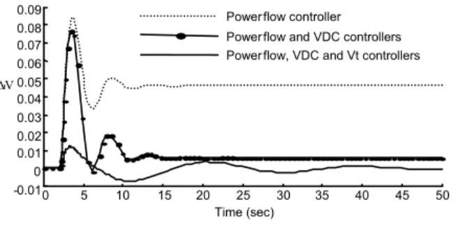
Fig. 10: Dynamic response of ∆Vt, following a 0.1 step
change in reference point of the power of line 2
Case 3: Power flow controller, DC voltage regulator and generator terminals voltage controller.
When only power flow controller is considered for UPFC, the responses are shown by dotted line in each figure. According to Fig. 8-11, In this case the dynamic responses of system including ∆ω, ∆VDC, ∆Pe2 and ∆Vt
are damped by suitable damping and also according to Fig. 8 (dotted curve in Fig. 8) the power transmission of line 2 is driven to 0.1 with good tracking characteristics after 0.1 step changes in reference point of power of line 2. But in this case because only power flow controller is considered, therefore the responses of
∆VDC and ∆Vt have steady-state error and cannot
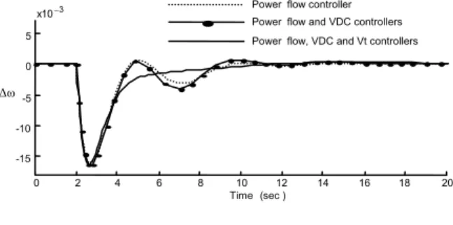
Fig. 11: Dynamic response of ∆ω, following a 0.1 step change in reference point of the power of line 2
Fig. 12: Dynamic response of ∆Pe2, following a 0.1
step change in mechanical torque
Fig. 13: Dynamic response of ∆VDC, following a 0.1
step change in mechanical torque
0 2 4 6 8 10 12 14 16 18 20
-0.02 0 0.02 0.04 0.06 0.08 0.1 0.12 0.14
∆P
e2
Power flow, VDC and Vt controllers Power flow controller Power flow and VDC controllers
Time (sec)
Power flow controller Power flow and VDC controllers Power flow, VDC and Vt controllers
0 2 4 6 8 10 12 14 16 18 20
-15 -10 -5 0 5
x10−3
∆ω
Time (sec )
Power flow controller Power flow and VDC controllers Power flow, VDC and Vt controllers
0 5 10 15 20 25 30 35 40 45 50
-0.4 -0.3 -0.2 -0.1 0 0.1 0.2 0.3 0.4 0.5 0.6
∆e2P
Time ( sec )
0 5 10 15 20 25 30
-2 -1.5 -1 -0.5 0 0.5 1
X10−3
Power flow controller Power flow and VDC controllers Power flow, VDC and Vt controllers
∆tV
Time ( sec )
0 5 10 15 20 25 30 35 40 45 50
-0.4 -0.3 -0.2 -0.1 0 0.1 0.2 0.3
∆DCV
Time (s ec)
Fig. 14: Dynamic response of ∆Vt, following a 0.1 step
change in mechanical torque
Fig. 15: Dynamic response of ∆ω, following a 0.1 step change in mechanical torque
driven back to zero (dotted curves in Fig. 9 and 10). In case 2, where power flow controller and DC voltage regulator are considered for UPFC, the responses are shown by dash-dot line in each figure. In this case the power transmission of line 2 is driven to 0.1 and DC voltage error is driven back to zero after a 0.1 step change in reference point of power of line 2 (dash-dot curves in Fig. 8 and 9). But in this case the response of
∆Vt has steady-state error and cannot driven back to zero, because the generator terminals voltage controller was not considered (dash-dot curve in Fig. 10). Also the damping of oscillation in this case in compare to case 1 is poor and the reason of this event is DC voltage controller. In fact when DC voltage controller is added to UPFC, this added controller has two sides: good side is DC voltage control and eliminates the steady state error in this signal and bad side is decrease of damping oscillations. In case 3, three controllers are considered for UPFC as power flow controller, DC voltage regulator and generator terminals voltage controller. In this case the dynamic responses are shown by solid line in each figure. In this case the power transmission of line 2 is driven to 0.1 and also DC voltage and generator terminals voltage error are driven back to
zero after a 0.1 step change in reference point of power of line 2 (solid curves in Fig. 8-10). Thus in this case the problem of steady-state error in responses is solved but this case has the disadvantage of reduction of damping oscillation of system in compare to other cases. In fact when three controllers are considered simultaneously, the results of control of VDC, Vt and Pe2
are appropriate but from view of system stability and damping oscillations this strategy is not an optimal and suitable strategy because it reduces the damping of oscillations. Therefore if system need to control of VDC,
Pe2 and Vt, thus it is necessary to design of three
controllers for VDC, Pe2 and Vt and the problem of
decrease of damping must be dissolved by other techniques such as adding two or more damping controller to UPFC for more dynamic stability or using power system stabilizer.
Dynamic responses to 0.1 step change in mechanical torque: Figure 12-15 show the dynamic responses to a 0.1 step change in mechanical torque. This section is similar to former section. Each figure contain three cases (case1: only power flow controller, case 2: power flow controller and DC voltage regulator and case 3: power flow controller, DC voltage regulator and generator terminals voltage controller).
When only power flow controller is considered for UPFC, the responses are shown by dotted line in each figure. According to Fig. 12 to 15, In this case, damping of the dynamic responses of system is good. But the responses of ∆VDC and ∆Vt have steady-state error and
cannot driven back to zero (dotted curves in Fig. 13 and 14). In case 2, where power flow controller and DC voltage regulator were considered for UPFC, the responses are shown by dash-dot line in each figure. In this case, DC voltage error is driven back to zero after a 0.1 step change in mechanical torque (dash-dot curve in Fig. 13). But ∆Vt has steady-state error and cannot driven back to zero (dash-dot curve in Fig. 14) and also the damping of oscillation in this case in compare to case 1 is poor. In case 3, power flow controller, DC voltage regulator and generator terminals voltage controller are considered. In this case, the dynamic responses are shown by solid line in each figure. Also, DC voltage and generator terminals voltage errors are driven back to zero after step 0.1 change in mechanical torque (solid curves in Fig. 13 and 14). Here, the problem of steady-state error in responses was solved but there is the disadvantage of reduction of damping oscillations of system in compare to other cases.
However, for increasing damping of oscillations a power system stabilizer or damping controller is needed.
Power flow controller Power flow and VDC controllers Power flow, VDC and Vt controllers
0 5 10 15 20 25 30 35 40 45 50
-2
-1.5
-1
-0.5 0 0.5 1 1.5 2 2.5
3 x10
−3
Time (sec)
∆ω
0 5 10 15 20 25 30 35 40 45 50
-0.01 0 0.01 0.02 0.03 0.04 0.05 0.06 0.07 0.08 0.09
∆tV
CONCLUSION
In this research application of UPFC for power flow and voltage control and simultaneously damping power system oscillation was investigated. GA have been successfully applied to tune the parameters of internal UPFC controllers. Design strategy includes enough flexibility to set the desired level of stability and performance.
The proposed method was applied to a typical SIMB power system installed with a UPFC. Three controller were considered for UPFC as power flow controller, DC voltage controller and generator terminals voltage controller and parameters of these controllers were tuned by GA. Simulation results demonstrated that when only power flow controller is considered for UPFC, the tracking of power transmission and damping oscillations are sufficiently achieved but DC voltage and generator terminals voltage have steady-state error. When power flow controller and DC voltage regulator are considered for UPFC, the tracking of power flow is performed and DC voltage error driven back to zero. But generator terminals voltage has steel steady-state error and damping oscillation is also poor in compare to the former case. Eventually, when all three controllers are considered, the tracking of power flow is performed and also DC voltage and generator terminals voltage steady-state errors are driven back to zero. But damping of oscillations is reduced in compare to other cases. For increasing of small signal stability, a power system stabilizer / damping controller is needed.
REFERENCES
1. Hingorani, N.G. and L. Gyugyi, 2000. Understanding FACTS. IEEE Press, 1st edition , New York, ISBN 0780334558.
2. Gyugyi, L. et al., 1995. The UPFC: A new approach to power transmission control. IEEE TPWRD, 10: 1085-1093.
3. Gyugyi, L., 1992. UPFC concept for facts. IEE Proc. C, 139: 323-331.
4. Al-Awami, A.T. et al., 2007. A particle-swarm-based approach of power system stability enhancement with UPFC. Elect. Power Energy Syst., 29: 251-259.
5. Liou, K.L. and Y.Y. Hsu, 1986. Damping of generator oscillation using SVC. IEEE Trans. Aero. Elect. Syst., 22: 605-617.
6. Liou, K.L. and Y.Y. Hsu, 1992. Damping of generator oscillation using an adaptive SVC. IEEE TPWRS, 7: 718-725.
7. Smith, J.R. et al., 1989. An enhanced LQ adaptive VAR unit controller for power system damping. IEEE TPWRS, 4 (2), 443-451.
8. Ni, Y. et al., 1998. Application of a Nonlinear PID Controller on STATCOM with a Differential Tracker. In: International Conference on Energy Management and Power Delivery, New York, USA, 3-5 March 98, pp: 29-34.
9. Zhao, Q. and J. Jiang, 1995. Robust SVC controller design for improving power system damping. IEEE TPWRS, 10: 1927-1932.
10. Parniani, M. and M.R. Iravani, 1998. Optimal robust control design of SVC. IEE Proc. C, 145: 301-307.
11. Farsangi, M.M. et al., 2000. Supplementary control design of SVC and STATCOM using H∞ optimal
robust control. In: International Conference Electronic Utility Deregulation and Restructuring and Power Technologies, City University, London, 4-7 April 2000, pp: 355-360.
12. Tambey, N. and M.L. Kothari, 2003. Damping of power system oscillation with UPFC. IEE Proc. C, 150: 129-140.
13. Wang, H.F., 1999. Damping Function of UPFC, IEE Proc.-C, 146: 129-140.
14. Yu Y.N., 1983. Electric Power System Dynamics. Academic Press, Inc., 1st edition, London.
15. Eldamaty, A.A. et al., 2005. Damping power system oscillation using a fuzzy logic based UPFC. IEEE CCECE/CCGEI, 1: 1950-1953.
![Figure 1 shows a SMIB power system with UPFC installed [1] . The UPFC is installed in one of the two parallel transmission lines](https://thumb-eu.123doks.com/thumbv2/123dok_br/18400948.358690/2.918.182.718.631.1018/figure-shows-smib-power-installed-installed-parallel-transmission.webp)