ISSN 1546-9239
© 2007 Science Publications
Corresponding Author: Omar Aliman, School of Electrical System Engineering, Kolej University Kejuruteraan Utara
Malaysia (KUKUM), 02600 Jejawi, Perlis, Malaysia, Tel: +604-9798146, Fax: +604-9798304
Tracking Error Analysis of a Rotation-Elevation Mode Heliostat
Omar Aliman, Ismail Daut, Muzamir Isa, Mohd Rafi Adzman
School of Electrical System Engineering, Kolej University Kejuruteraan Utara Malaysia (KUKUM) 02600 Jejawi, Perlis, Malaysia
Abstract: For the past few years, great efforts have been done in improving the tracking accuracy of a newly proposed rotation-elevation tracking mode heliostat. A special simulation program has been developed to systematically analyze the image movement and to find out the error of the parameters. In the simulation program, ray-tracing method was applied to work out the central point position of the master mirror image on the target plane during the primary tracking. From the experiment, less than 5cm of tracking error was achieved with the help of the simulation program. We discussed the error analysis of the two prototypes of so called Non-Imaging Focusing Heliostat (NIFH) in University Teknologi Malaysia (UTM) which has greatly reduced the optical alignment process and resulting more precise result.
Key words: Ray tracing, heliostat, optical alignment, solar energy
INTRODUCTION
The two prototypes of NIFH[1] built in UTM are structurally close-loop. The feedback signal from the optical encoder will eliminate the tracking error due to the mechanical lashes, wind effect and other disturbances to the heliostat frame. The pointing error existed in the tracking is basically due to the error of the parameters (i.e. the orientation angles of the rotation axis respect to the target, the latitude, etc.) and the imperfection of mechanical design. The imperfections of the mechanical design in the heliostat structure are the translation offset of reflector from the elevation axis, the mechanical alignment between the elevation axis and the rotation axis etc. In order to determine the accurate parameter, systematic analysis of the image movement has been performed using computer simulation.
Computer simulation: The primary tracking error analysis is performed base on the simulation program developed by Chong[2]. In the analysis, only a single beam that strikes on the central point of the master mirror is traced. The flow chart of the algorithm for computing and plotting the pattern of master mirror image movement from time to time in the daily sun tracking is illustrated in Fig. 1. In the beginning of the program, the user must enter the measured parameters (which we will use to calculate the heliostat orientation angles for the sun tracking), the actual parameters
(which will cause the tracking error), the common parameters, the error of rotation angle (δρ) and the error of elevation angle (δθ). The measured parameters and actual parameters include facing angle (ϕandϕ'
), target angle (λandλ'
), latitude (φandφ'
) and number of the day (NOD and NOD’). The common parameters that needed in the simulation are such as target distance (L), longitudinal correction (LongC), offset distance of the reflector from the elevation axis (EOff), time delay of the heliostat tracking (δLCT) and encoder revolution (Rev). There are two options in the simulation program: one is the target orientation and the other is the correction of the reflector from the elevation axis.
In the program algorithm, the computation of the sun position angles (β',ρ') and the heliostat orientation angles (θ,ρ) will be done first. The angles β' and ρ' are estimated through the equation (3.31) and (3.32) from the actual parameters such as φ'
,λ'
,φ'
, NOD’ and LCT-
δ
LCT. On the other hand, the angles θ (elevation movement) and ρ (rotation movement) are computed through the Eq. (1) and (2) from the measured parameters such asφ
,λ
,φ
, NOD and LCT.Cos Cos Sin Sin Cos Sin Cos Sin Sin Cos ArcSin
Cos
− δ ω φ Φ + δ ω φ + δ φ Φ
ρ = β
( )
( )
Cos Cos Sin Cos Cos Cos Sin Cos Sin 1
ArcSin
4 2 Cos Sin Sin Cos Cos Cos Sin Sin
− δ ω λ Φ + λ φ Φ − δ ω
π
θ = −
λ φ + δ λ φ Φ − Φ λ
(2)
Another consideration of the tracking error is the achievable precision of the heliostat orientation angles. It is limited by the encoder revolution where the smallest steps size of the angles θ and ρ are equal to 2
π
/Rev. From the angles θ, ρ, β'andρ'
, the central point coordinate of the master mirror, the unit vector of incidence ray, the unit vector of master mirror normal and the unit vector of reflected ray can be determined
Input parameters: 1. measured parameters φ ', λ', Φ', NOD' 2. actual parameters φ, λ, Φ, NOD 3. common parameters L, LongC, EOff, δLCT, Rev
i = 0 i = i + 1
Is i =< N? Start
End Yes
No
Calculate the heliostat orientation from the measured parameters: LCT[i]= LCTmin + i*(LCTmax-LCTmin)/N
ρ[i], β[i], and θ[i]
Calculate the sun position angles from the actual parameters: LCT'[i]= LCTmin + i*(LCTmax-LCTmin)/N - δLCT
ρ'[i], and β '[i]
Calculate (H'[i].x, H'[i].y, H'[i].z): Coordinate transformation on (0, 0, EOff) due to
the angles of ρ[i] and θ[i]
Calculate the unit vector of incident rays: (I[i].x, I[i].y, I[i].z)
Calculate the unit vector normal to the master mirror:
(N[i].x, N[i].y, N[i].z)
Calculate the unit vector of reflected ray: (R[i].x, R[i].y, R[i].z)
Calculate the hitting point of reflected ray on the target: (HPoint[i].x, HPoint[i].y, HPoint[i].z)
Get LCTmin, LCTmax and N
Fig. 1: Flowchart of the simulation program algorithm in primary tracking error analysis
through the Eq. (3)-(6). Finally from the Eq. (7), the hitting point of sunray at the target will be obtained. This algorithm will iterate N times starting from local time 0800 (LCTmin) and ending at local time 1800 (LCTmax). The following is the equations used in the simulation to obtain the central point of master mirror images on the target during the daily sun tracking:
[ ] [ ] [ ] [ ]
(
)
( )
[ ] [ ]( )
( )
[ ] [ ]( )
EOff cos i sin i H ' i .x
H ' i .y EOff sin i sin i H ' i .z EOff cos i
ρ θ
= − ρ θ
θ
(3)
[ ] [ ] [ ]
I i .x cos 'cos ' I i .y cos 'sin ' I i .z sin '
β ρ
= − β ρ
β
(4)
[ ]
[ ]
[ ]
N i .x sin cos N i .y sin 'sin
N i .z cos
θ ρ
= − θ ρ
θ
(5) [ ] [ ] [ ] [ ] [ ] [ ] [ ] [ ] [ ] ( ) [ ] [ ] [ ] [ ] [ ] [ ] [ ] [ ] ( ) [ ] [ ] [ ] [ ] [ ] [ ] [ ] [ ] ( ) [ ] [ ]
2 I i .xN i .x I i .yN i .y I i .zN i .z N i .x I i .x R i .x
R i .y 2 I i .xN i .x I i .yN i .y I i .zN i .z N i .x I i .y R i .z 2 I i .xN i .x I i .yN i .y I i .zN i .z N i .x I i .z
+ + − = + + − + + − (6)
[ ]
[ ]
[ ]
[ ]
(
[ ]
)
[ ]
[ ]
[ ]
(
[ ]
)
[ ]
[ ]
[ ]
(
[ ]
)
[ ]
[ ]
R i .x L H ' i .z / R i .z H ' i .x HPo int i .x
HPo int i .y R i .y L H ' i .z / R i .z H ' i .y HPo int i .z R i .z L H ' i .z / R i .z H ' i .z
− + = − + − + (7)
Tracking error analysis: Simulation program analysis on the tracking error study has been adopted in the first prototype (with the target distance of 10m) and second prototype (with the target distance of 16.5m) of NIFH heliostat. Since the optical encoders used in the system are incremental type, the initial values of elevation angle
θ
and rotation angleρ
have to be provided. These initial values are measured using slant level (90° range, 0.5° error). Normally, in order to reduce the measurement error we normally initialize the heliostat to the orientation at solar noon in which the arm is horizontal.The computer program had no way to determine the absolute position of the heliostat since incremental optical encoders were applied in the control system. Even though the last position of heliostat can always be recorded for reference in the next operating schedule, there is no guarantee that heliostat position will not change due to external disturbances when computer is turned off. Therefore, prior to a new tracking session, the initial position of heliostat, the rotation and elevation of master mirror, were manually measured and entered into the program. Then, the starting time of a tracking session was set.
Throughout the experiment, this method can achieve a reasonable good accuracy in sun tracking. One of the major errors that cannot be avoided in the measurement of facing angle is the deviation between the direction of true north and the magnetic north. However, the precision of the facing angle,
φ
and target angle,λ
measurement can be further corrected through the tracking error analysis study using simulation program.RESULTS
angle are estimated to be 0° and 0° respectively. During the daily sun tracking, the image of the master mirror on the target is recorded using CCD camera from 0836 hour to 1815 hour on August 18 as shown in Fig. 2. From the recorded tracking error pattern, the actual parameters can be analyzed and predicted through the simulation program. In the simulation, the actual facing angle
φ
'
is 0.2°, target angleλ
'
is 0.1°, measurement error of elevation angleδθ
is estimated as 0.02° and rotation angleδρ
is 0.15°.On the next day, the sun tracking are performed from 0912 hour to 1730 hour with the predicted actual parameters, e.g. the facing angle is 0.2° and the target is 0.1°. With this setting, the longest distance between two master images is less than 2.5cm for 8 hours of sun tracking.
Fig. 2: Observation on August 18, 2005
Fig. 3: The recorded result of the tracking error pattern on July 13
Another experiment that was conducted by Chong[2], the measured facing angle and target angle are estimated as -0.6° and 0° respectively. During the daily sun tracking, the image of the master mirror on the target is recorded using CCD camera (Fig. 3) from 1205 hour to 1730 hour on July 13. From the recorded tracking error pattern, the nearest tracking error pattern of the simulated result to the experimental result are shown as Fig. 4. In the simulation, the actual facing angle φ’ is 1.2°, target angle λ’ is 0°, measurement
error of elevation angle δθ is estimated as 0.01° and rotation angle δρ is 0.15°.
On the next day, the sun tracking are performed from 1330 hour to 1802 hour with the predicted actual parameters, e.g. the facing angle is 1.2° and the target angle is 0°. With this setting, the longest distance between two master images is less than 2.5cm for 4½ hours of sun tracking (Fig. 5).
Fig. 4: The simulation result of the daily tracking error pattern
Fig. 5: The pattern of sun tracking from 1330 hour to 1802 hour on 14 July with the predicted actual parameters
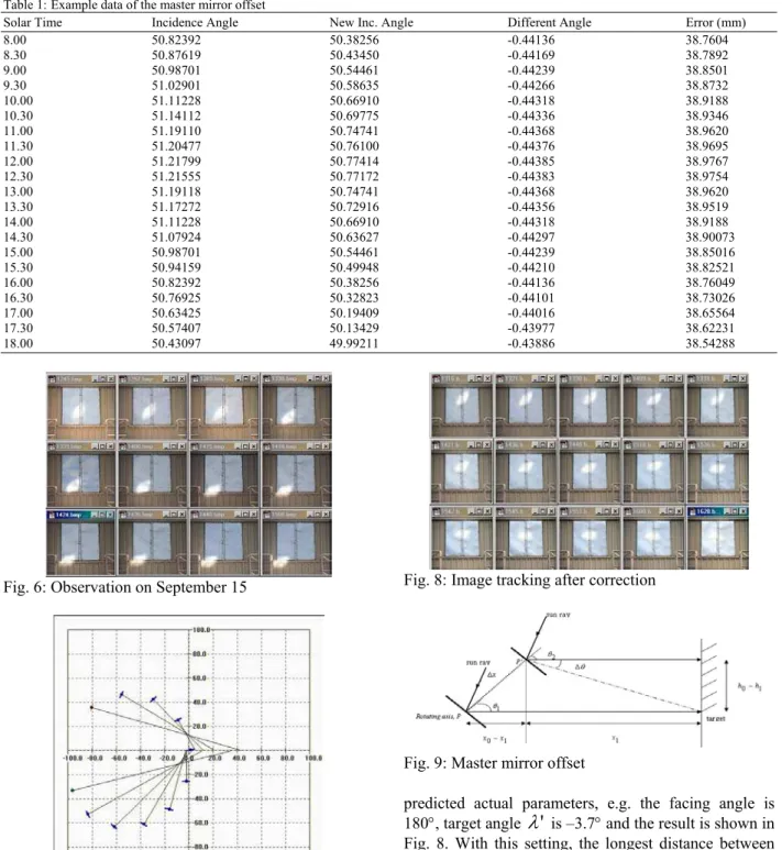
Table 1: Example data of the master mirror offset
Solar Time Incidence Angle New Inc. Angle Different Angle Error (mm)
8.00 50.82392 50.38256 -0.44136 38.7604 8.30 50.87619 50.43450 -0.44169 38.7892 9.00 50.98701 50.54461 -0.44239 38.8501 9.30 51.02901 50.58635 -0.44266 38.8732
10.00 51.11228 50.66910 -0.44318 38.9188
10.30 51.14112 50.69775 -0.44336 38.9346
11.00 51.19110 50.74741 -0.44368 38.9620
11.30 51.20477 50.76100 -0.44376 38.9695
12.00 51.21799 50.77414 -0.44385 38.9767
12.30 51.21555 50.77172 -0.44383 38.9754
13.00 51.19118 50.74741 -0.44368 38.9620
13.30 51.17272 50.72916 -0.44356 38.9519
14.00 51.11228 50.66910 -0.44318 38.9188
14.30 51.07924 50.63627 -0.44297 38.90073
15.00 50.98701 50.54461 -0.44239 38.85016
15.30 50.94159 50.49948 -0.44210 38.82521
16.00 50.82392 50.38256 -0.44136 38.76049
16.30 50.76925 50.32823 -0.44101 38.73026
17.00 50.63425 50.19409 -0.44016 38.65564
17.30 50.57407 50.13429 -0.43977 38.62231
18.00 50.43097 49.99211 -0.43886 38.54288
Fig. 6: Observation on September 15
Fig. 7: The simulation result of the daily tracking error pattern on September 15
Finally, three days later, the sun tracking are performed from 0924 hour to 1621 hour with the
Fig. 8: Image tracking after correction
Fig. 9: Master mirror offset
predicted actual parameters, e.g. the facing angle is 180°, target angle
λ
'
is –3.7° and the result is shown in Fig. 8. With this setting, the longest distance between two master images is less than 4.5cm for 8 hours of sun tracking.Fig. 9. The center of the master mirror should be placed exactly at the rotating axis point, P. But, if there is an offset, ∆x from the rotating axis, P and the center point of the master mirror, P’, the incidence angle, θ should be corrected as,
new
θ
= θ + ∆θ
(8)where, ∆θ is the correction of the incidence angle
1
0
x sin tan
x x cos
− ∆ θ
∆θ =
− ∆ θ
(9)
Table 1 illustrates an example of the data taken on August 19, using the first prototype of NIFH. For an offset of 0.5cm, the image distance from the ideal position is about 39mm. Obviously, the image will not focus to a stationary target. The longer the distance between the heliostat and the target, the bigger error will be made.
ACKNOWLEDGMENT
We acknowledge with many thanks to Prof. Y.T.Chen and members of Solar Group which we formerly in the same team and effort, together struggling for the success of this research while we were in Universiti Teknologi Malaysia.
CONCLUSION
From the experiment, both prototypes of the NIFH heliostat achieved less than 5cm tracking error in average. The factors of master mirror offset, the accuracy of the measurement and high resolution of the positioning device have been identified to contribute errors. New calculation of the incidence angle, new technique to make alignment and high performance device has been implemented to reduce the problems. The introductions of the optical alignment methods have significantly reduced the time and manpower cost. Due to the uncertainty of the structural rigidity upon installation of the frame at the arm of the heliostat, further alignment work has to be done to confirm the rotational axis of the heliostat frame.
REFERENCES
1. Chen, Y.T., K.K. Chong, O. Aliman, T.P. Bligh1, L.C. Chen, J. Yunus, K.S. Kannan, B.H. Lim, C.S. Lim, M.A. Alias, N. Bidin, S. Salehan, S.A. Rezan S.A.H., C.M. Tam and K.K. Tan, 2001. Non-imaging focusing heliostat. Intl. J. Solar Energy, 71: 155-164.