Ricardo Filipe Martins Beatriz
Licenciado em Ciências da Engenharia e Gestão Industrial
Safety Function Analysis in an
Industrial Production Process
Dissertação para obtenção do Grau de Mestre em Engenharia e Gestão Industrial
Orientadora: Professora Doutora Maria Celeste Rodrigues Jacinto, Professora Auxiliar da Faculdade de Ciências e Tecnologia da Universidade Nova de Lisboa
Júri:
Presidente: Doutora Virgínia Helena Arimateia de Campos Machado Arguente: Doutor Pedro Manuel de Araújo Antão
Arguente: Mestre Filipe José Martins Carracinha Vogal: Doutora Maria Celeste Rodrigues Jacinto
Safety Function Analysis in an Industrial Production Process © 2012 Ricardo Filipe Martins Beatriz
Faculdade de Ciências e Tecnologia – Universidade Nova de Lisboa
iii
Acknowledgements
I am very grateful to my thesis supervisor, Dr. Celeste Jacinto, who has supported me throughout my work with her patience and knowledge whilst allowing me the room to work in my own way. One simply could not wish for a better or friendlier supervisor. The method applied in the work was developed by professor Harms-Ringdahl, who I want to acknowledge too for his comments and good-will to help along the work.
My gratitude also goes to Renova’s Engineers Filipe Carracinha and Liliana Inácio, who provided me all the necessary support on the analysis of the processes, and to Renova’s Administration who gave me all the necessary conditions to make it possible.
I would like to thank my friends that always encouraged and motivated me to keep up my work.
Resumo
Objetivo: Este trabalho teve como objetivo identificar e avaliar aspetos de segurança numa linha de produção de uma empresa transformadora de papel chamada Renova. A avaliação contemplou fatores técnicos e também fatores organizacionais e de gestão. O estudo foi realizado através da avaliação de funções de segurança (FS), presentes ou não, no sistema produtivo. Métodos: Para a realização do estudo foi aplicada uma versão nova e mais recente do método SFA (Safety Function Analysis), desenvolvido por Harms-Ringdahl, primeiro em 2001 e mais tarde em 2011, ainda em rascunho. Esta
metodologia foi aplicada em dois processos (“raw material loading” –carregamento de matéria-prima e “transversal cut of log” –corte transversal de charuto) de uma linha de produção (H4) da empresa referida. Resultados: No primeiro processo analisado (carregamento de matéria-prima), foram identificadas e avaliadas 47 funções de segurança; o segundo processo (corte transversal de charuto) consubstanciou 36 funções de segurança. A maioria das funções de segurança avaliadas apresenta boas condições de funcionamento e monitorização adequada; por isso não necessitam de quaisquer melhorias. No entanto, foram também encontrados casos que necessitam de melhorias essenciais. Conclusões: Como consequência da análise realizada com o método SFA, foram feitas recomendações concretas ao nível da segurança, de forma a melhorar o desempenho geral do sistema; sendo uma fábrica de transformação de papel, é importante a implementação de testes termográficos que possibilitem identificar pontos quentes, suscetíveis de originar focos de incêndio.
v
Abstract
Aim: The purpose of this work was to identify and assess safety features on a production line of paper manufacturer called Renova. The assessment includes technical as well as organisational factors. The study was carried out through the evaluation of safety functions (SF), either present or absent in the system analyzed. Methods: The methodology applied was the SFA (Safety Function Analysis), which was developed by Harms-Ringdahl in 2001 and was updated further, in 2011 (draft version). The analytical framework was applied in two processes (raw material loading and transversal cut of log) of a production line (Line H4) of Renova. Results: In the first process analyzed (raw material loading), 47 safety functions (SF) were identified and evaluated, whereas 36 SF were assessed in the second case (transversal cut of log). The evaluation has shown that most of the SF considered are in good condition and being well monitored, therefore they do not need any improvements. In contrast, this work has also identified a number of safety functions that need essential improvements. Conclusions: As a consequence of this SFA analysis, the author proposes a number of
specific recommendations to improve safety and the system’s performance in general. Since Renova is a manufacturer of paper products, fire safety is of paramount importance and one of the most relevant recommendations is perhaps the implementation of thermo graphic tests to identify possible hot spots that may originate a fire.
Table of contents
Acknowledgements ………iii
Resumo ... iv
Abstract ... v
List of Figures ... vii
List of tables ... viii
Acronyms and abbreviations ... x
1. Introduction ... 1
2. State of the art (theory and legal issues) ... 4
2.1 Literature Review ... 4
2.1.1 Risk Analysis (RA) ... 4
2.1.2 Safety Analysis (SA) ... 7
2.1.3 Methods (Tools) ... 14
2.2 EU Directives and practical/legal requirements ... 17
2.3 Synthesis of chapter ... 22
3. Methodology ... 24
3.1 Introduction ... 24
3.2 Risk Assessment – method currently used in Renova ... 24
3.3 Safety Function Analysis (2001, 2003a) ... 27
3.4 Safety Function Analysis (New development; Harms-Ringdahl, 2011 draft) ... 32
4. Case Study ... 39
4.1 Renova (company description) ... 39
4.2 Process Description ... 41
5. Application of SFA method ... 47
5.1 First Process – Raw material loading ... 47
6. Discussion of Results ... 57
6.1 Discussion of results of the process “raw material loading” ... 57
6.2 Discussion of results of the process “transversal cut of log” ... 59
6.3 Synthesis of Chapter ... 60
7. Conclusions ... 62
References... 64
Appendix I ... 66
Appendix II ... 72
List of figures
Figure 2.1 - Relation between frequency and consequence (adapted from Harms-Ringdahl, 2001, p. 46)………... 5Figure 2.2 - Safety through prevention and protection (Hollnagel, 2008, p. 222)………8
Figure 2.3 - The Energy model (based on Haddon, 1980; cited by Sklet, 2006)………..8
Figure 2.4 - Example of safety barrier diagram (Dujim, 2009, p. 333)………12
Figure 3.1 - The six stages of SFA (adapted from Harms-Ringdahl, 2003a)………...28
Figure 3.3 - Flowchart representing differences between SFA versions of 2001 and 2011……33
Figure 4.1 - Safety and Health at work services of Renova (supplied by Renova, 2011)………40
Figure 4.2 - Renova's Production Process and respective factories………...41
Figure 4.3 - Raw material loading………43
Figure 4.4 - Log accumulation……….44
Figure 4.5 - Longitudinal cut of core………46
Figure 5.1 – AGV transporting raw material + photoelectric sensor………...49
List of tables
Table 2.1 - Scale for consequences and probability values (adapted from Harms-Ringdahl, 2001,
p. 48)………...6
Table 2.2- Barrier systems and respective barrier functions (Adapted from Hollnagel, 2008, p. 226)………...10
Table 2.3 - Evaluation of barrier system quality (Adapted from Hollnagel, 2008, p. 228)…….11
Table 2.4 - Some methods of Safety Analysis (adapted from Harms-Ringdahl, 2001, p. 41)….14 Table 3.1 - Level of Deficiency classification (Renova, 2011; WTF modified)………..25
Table 3.2 - Level of exposure classification (Renova, 2011; WTF modified)……….25
Table 3.3 - Level of Probability (Renova, 2011; WTF modified)………26
Table 3.4 - Level of Consequence (Renova, 2011; WTF modified)………26
Table 3.5 - Level of Risk evaluation (Renova, 2011; WTF modified)………27
Table 3.6 - Categories of SF characteristics (Harms-Ringdahl, 2003a, p. 707)……….…..30
Table 3.7 - Scale to apply judgment of acceptability (Harms-Ringdahl, 2001, 2003a)………...31
Table 3.8 - Classification of Intention of Safety Functions (Harms-Ringdahl, 2011 draft, chapter 11)……….34
Table 3.9 - Classification of Importance of SF (Harms-Ringdahl, 2011 draft, chapter 11)…….34
Table 3.10 - Scale of efficiency for SF based on frequency of error or probability (Harms-Ringdahl, 2011 draft, chapter 11)……….35
Table 3.11 - Need of monitoring, and judgment of status (adapted from Harms-Ringdahl, 2011 draft, chapter 11)………..35
Table 3.12 - Evaluation scale for acceptability of safety function (adapted from Harms-Ringdahl, 2011 draft, chapter 11)……….36
Table 3.13 - Table of decision rules for SFs (Harms-Ringdahl, 2011 draft, chapter 11)……….37
Table 5.1 – Example of the safety function evaluation for the process raw material loading….48 Table 5.2 - Example of corrective actions proposed for the process raw material loading…….51
Table 5.3 - Example of the safety function evaluation for the process transversal cut of log….54 Table 5.4 - Example of corrective actions proposed for the process transversal cut of log…….56
Table 6.1 - Synthesis of safety functions, by hazard and group of SF in the “raw material loading”………57
Table 6.3 - Synthesis of safety functions, by hazard and group of SF in the “transversal cut of
log”………...59
Table 6.4 - Synthesis of the proposed recommendations to the “transversal cut of log”……….60
Table A1 - Safety function evaluation for the process raw material loading (1/2)………..67
Table A1 (continued) - Safety function evaluation for the process raw material loading (2/2)..68
Table A2 - Corrective actions proposed for the process raw material loading (1/3)…………...69
Table A2 (continued)-Corrective actions proposed for the process raw material loading (2/3)..70
Table A2 (continued)-Corrective actions proposed for the process raw material loading (3/3)..71
Table A3 - Safety function evaluation for the process transversal cut of log (1/2)………..73
Table A3 (continued) - Safety function evaluation for the process transversal cut of log (2/2)..74
Table A4 - Corrective actions proposed for the process transversal cut of log (1/3)…………...75
Table A4 (continued)-Corrective actions proposed for the process transversal cut of log (2/3)..76
Acronyms and Abbreviations
ADM Administration
AGV Automated Guided Vehicle
CS “Comissão de Segurança” - Safety Commission DIFA “Divisão de Fabricação” -Fabrication Division DIRE “Divisão de Reciclagem” - Recycling Division
DISA “Divisão de Produtos Sanitários” - Sanitary Product Division DITA “Divisão de Transformação” -Transformation Division DMRA Decision Matrix Risk-Assessment
EMAS Eco-Management and Audit Scheme ETA Event Tree Analysis
FTA Fault Tree Analysis
HAZOP Hazard and Operability Studies JSA Job Safety Analysis
PEA Predictive, Epistemic Approach
PEI “Plano de Emergência Interno” – Internal Emergency Plan PRAT Proportional Risk-Assessment Technique
RAA Risk Analysis and Assessment RBM Risk-based Maintenance
RGS “Responsável pela Gestão de Segurança” - Responsible for the Safety Management System
RSS “Responsável pelos Serviços de Segurança” - Responsible for Safety Services
SF Safety Function
SFA Safety Function Analysis
SHST “Serviços de Saúde e Segurança no Trabalho” – Health and Safety at Work Services
1.
Introduction
Safety at work can be supported by several analytical and practical approaches. However, when talking about safety one must refer to risk too, once risk and safety are linked both conceptually by comparing definitions, and pragmatically through its reciprocity, since a higher level of safety its equivalent to a lower level of risk.
There is an increased need to improve safety along the passing years, and such need requires methods to explore/examine workplaces, machinery, processes, and even entire factories if needed. All the methods must contribute to the risk elimination or the reduction of consequences, through hazard identification and safety improvement. The Energy model, for instance, is one of the many approaches for the analysis of safety characteristics, in which “defense” and “barrier” are general concepts that represent several types of safety features. In a general and simple way, the defenses should prevent hazards from causing losses. This method, like many others, usually involves technical and organizational barriers. This term, as well the term “safety barrier”, is frequently used in risk assessment literature. Hollnagel (2008) describes them as being physical or non-physical obstacles that can be created to prevent unwanted events, or protect them from more serious consequences.
A new methodology to risk assessment was created by Harms-Ringdahl from 2000 (Harms-Ringdahl, 2001, 2003a, 2003b); it is based on the study of safety functions identified within a certain hazard. This methodology is known as Safety Function Analysis (SFA). The method is generic and can be applied to most types of systems or events; however when assessing safety, it is considered as a specific evaluation, once only the most significant hazards, previously identified by traditional methods, are included in a SFA study.
company to analyze and improve the safety features of a particular production line; the referred line is quite long and involves a range of possible hazards. Another aspect that motivated the application of this particular approach is the fact that the older version of SFA had been applied in the same company in 2009 (Carracinha and Jacinto, 2009). This thesis is structured in seven chapters, which will be shortly described below.
The second chapter presents a summary of the theoretical and practical framework, splitting it into two topics. In the theoretical topic, the literature review is divided in three parts, related to risk analyses and safety analyses. There are important concepts discussed, such as risk definitions in the first part, and the different notions of
“Barriers” addressed to “Safety Functions” in the second part. The third part of this literature review refers to some different methods used in “Risk Analyses” and “Safety Analyses” where the Safety Function Analysis (SFA) method is briefly introduced. The practical topic refers to the legal requirements applicable to the case study presented in this work, namely the machinery and the use of equipment directives. These legal requirements set the starting point to identify the safety functions used in the checklists of the SFA method.
In the third chapter the author describes the methodology of this work. It is described the original version of the SFA method (2003) and its six phases of implementation, suggested by Harms-Ringdahl. Then, the new version of the method is presented together with its differences from the original. For better understanding it will be presented a flowchart that highlights the differences between the two versions of the SFA method. These differences will be explained in more detail, one by one, regarding its application in the case study.
The host company (Renova) of this work is presented in chapter four, with a short characterization of its productive processes. The chosen process for the case study, where the SFA method is applied, is described in detail too.
2. State of the art (theory and legal issues)
In this chapter important concepts will be discussed to facilitate understanding of the work. When doing this it is important referring to both theoretical and practical issues, such as the literature review and the not least important, legal requirements. This chapter is structured into two topics so it can be explained in more detail.
2.1
Literature Review
The first topic embraces the most theoretical aspects of scientific literature in this domain; it will approach three main points regarding work safety: risk analysis, safety analysis and methods; which will be explained next.
2.1.1 Risk Analysis
Within an industrial plant, one can either talk about industrial (operational) or occupational risks. This work is more focused on occupational risk, but it also takes into account industrial risk such as fire and explosion, handling of substances hazardous to health and environment or even risk of chemical release.
The definition of risk has been changing over the years, so it is not easy to find one universal definition. When the word risk is used, it concentrates the effects of change as well as the difficulty to predict it. Villemeur, for instance, defines risk as a “hazard measure combining a measure of the occurrence of an undesirable event and a measure of its effects or consequences.” (Villemeur, 1992; p.708).
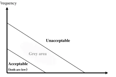
For example, in the acceptable zone the risk is below the limits of acceptance; it means that there is both low probability of occurrence and small consequences if an accident occurs. On the other hand, in the unacceptable zone, there is a high probability of occurrence and serious consequences if an accident takes place; it means that urgent measures must be taken to reduce the probability and/or the gravity level. The grey area zone of the risk is a complicated issue, especially in large and complex systems. It can be applied the ALARP (As Low As Reasonably Practicable) principle, which means that the best that can be done under prevailing circumstances must be done.
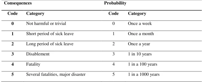
Numerical quantified estimates are difficult to classify risk and it takes quite an effort. So, a common approach is to classify risks according to consequences and their frequency of occurrence; however this is a qualitative assessment, or at most a semi-quantitative one, since it returns estimated results instead of definitive values, and is
based on people’s judgments. Table 2.1 provides an example of a scale for
consequences and probability values.
Frequency
Consequence Acceptable
(both are low)
Unacceptable
Grey area
Table 2.1 - Scale for consequences and probability values (adapted from Harms-Ringdahl, 2001, p. 48)
Consequences Probability
Code Category Code Category
0 Not harmful or trivial 0 Once a week
1 Short period of sick leave 1 Once a month
2 Long period of sick leave 2 Once a year
3 Disablement 3 1 in 10 years
4 Fatality 4 1 in a 100 years
5 Several fatalities, major disaster 5 1 in a 1000 years
When addressing occupational safety and health, in particular, the definitions more commonly used are standardized as follows:
Hazard: source, situation, or act with a potential for harm in terms of human injury or ill health, or a combination of these (OHSAS 18001, 2007, p.2)
Risk: combination of the likelihood of an occurrence of a hazardous event or exposure(s) and the severity of injury or ill health that can be caused by the event or exposure(s) (OHSAS 18001, 2007, p.4)
Risk assessment: process of evaluating the risk(s) arising from a hazard(s), taking into account the adequacy of any existing controls, and deciding whether or not the risk(s) is acceptable (OHSAS 18001, 2007, p.5)
In short, when straightening the concept to occupational risk, it refers to the likelihood and severity of an injury or an illness to take place as a result of exposure to a hazard,
being “hazard” something that has the potential to cause harm to people.
HAZOP, etc) are based on analytical estimation processes and on the safety managers/engineers ability. As for the quantitative techniques (PRAT technique, DMRA technique, PEA method, etc), risk can be estimated and expressed by a mathematical relation, using real accident data, recorded in a work site; in this case, as the name suggests, the risk can be considered as a quantity. The hybrid techniques (FTA, ETA, RBM, etc) are usually very complex and have sometimes an ad hoc nature, which may prevent their wide use. These authors’ review (Marhavilas et al, 2011), covering the decade 2000 to 2009, conclude that papers with RAA techniques still constitute a very small part of the scientific literature.
2.1.2 Safety Analysis
In practice, the concepts of risk analysis and safety analysis are complementary to each other. If one considers, by analogy, that a scale from 0 to 1 is used, with a risk level around 0.3, this means that the safety level is around 0.7. What changes is the way one looks at the phenomena: either by the risk side, or by the safety side.
Barriers
Harms-Ringdahl (2001, 2003a, 2003b, 2004) states that some authors use the term barrier to identify organizational aspects, while others use terms such as: barrier function; defense or protection layer. Hollnagel (2004) characterizes the term barrier as prevention or protection; they can be used before or after the action takes place in time regarding the prevention or the protection. There are different concepts and terminology related to the term barrier as the ones given by Harms-Ringdahl and Hollnagel.
Other possible classifications are active barriers or passive barriers. Active barriers imply the need to do a certain safety function, while passive barriers have any defined action, but their simple presence in a system is the function. Hollnagel (2004) classify the active barriers as permanent or temporary; where permanent barriers are normally included in the project phase, while temporary barriers are used in timely situations such as occasional workout.
Figure 2.2 - Safety through prevention and protection (Hollnagel, 2008, p. 222)
The term safety barrier was firstly used by Gibson in 1961, as result of the application of an energy model (Fig. 2.3) in accident investigation, later by Haddon in 1980, in the subsequent development of the same model, when he presented the ten accident prevention strategies (c.f. Sklet, 2006). On the other hand, Hollnagel states that:
“whereas the barriers used to defend a medieval castle mostly were of a physical
nature, the modern principle of defense-in-depth combines different types of barriers— from protection against the release of radioactive materials to event reporting and
safety policies.”(Hollnagel, 2004, p. 71)
The safety barriers are critical to reduce the risk of accidents, so that their importance is demonstrated by risk-informed principles and safety barriers in European regulations such as the Seveso II directive (EC, 1996) and Machinery Directives (DL-103/2008).
Sklet (2006b) proposes some definitions of Safety Barriers, Barrier Functions and Barrier Systems:
“A Barrier System is a system that has been designed and implemented to perform one
or more barrier functions” (Sklet, 2006b, p.496).
It describes how a certain barrier function is executed. A barrier system may consist in different kinds of elements, physical or technical, operational activities performed by people, or the combination of both. There are different manners to classify barrier systems, depending on the authors (e.g.: Hollnagel, 2004, 2008; Sklet, 2006a; Sklet 2006b; Duijm, 2009).
In turn, barrier systems can be characterized by four types of possible barriers (Table 2.2).
Physical barriers are incorporated in the design of the construction; these systems stop an action/event using physical means and can be used against energy, material and people. For example: walls, doors, grids, etc. In general, technical barriers are initiated if a hazard is triggered.
Functional barriers are defined by logical conditions that stop an action to take place in time, meaning that the function needs to meet one or more pre-requirement so the action
can be performed. These requirements don’t need to be visible or perceptible to an
operator; however its presence is indicated (e.g. establishing an interlock, either logical or temporal (c.f. Leveson, 1995)).
Table 2.2- Barrier systems and respective barrier functions (Adapted from Hollnagel, 2008, p. 226)
Barrier System Barrier Function Example
Physical
Contain or protect. Walls, doors, buildings, filters, containers, tanks, valves, rectifiers, etc.
Prevent transporting something from the present location (release) or into another (intrusion).
Safety belts, harnesses, fences, cages, etc.
Keep together. Cohesion, resistance.
Safety glass.
Functional
Prevent movement or action (mechanical, hard).
Locks, equipment alignment, physical interlocking, equipment match, etc.
Prevent movement or action (logical, soft).
Passwords, entry codes, action sequences, pre-conditions, physiological matching, etc.
Hinder or impede actions (spatio-temporal).
Distance, persistence, delays, synchronization, etc.
Symbolic
Counter, prevent or stop actions (visual, tactile interface design)
Coding of functions, demarcations, labels & warnings, etc.
Regulate actions. Instructions, procedures, dialogues, etc.
Incorporeal
Comply, conform to Self-restraint, ethical norms, etc.
Prescribing: Rules, laws, guidelines, prohibitions
Rules, restrictions, laws, etc.
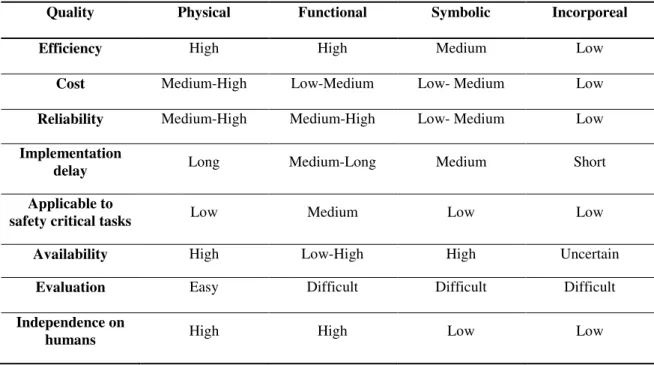
Efficiency – How well the barrier meets its intended purpose;
Cost – What is needed to design, develop and maintain a barrier;
Reliability – The ability to maintain its functions in routine circumstances;
Implementation delay – The time from conception to implementation of a barrier;
Applicable to safety critical tasks – The use in safety tasks;
Availability – Whether a barrier can fulfill its purpose when needed;
Evaluation – How easy is to determine whether a barrier works as expected;
Independence on humans – The ability of not depending on humans to achieve its purpose.
Table 2.3 shows the above quality attributes of each barrier system.
Table 2.3 - Evaluation of barrier system quality (Adapted from Hollnagel, 2008, p. 228)
Quality Physical Functional Symbolic Incorporeal
Efficiency High High Medium Low
Cost Medium-High Low-Medium Low- Medium Low
Reliability Medium-High Medium-High Low- Medium Low
Implementation
delay Long Medium-Long Medium Short
Applicable to
safety critical tasks Low Medium Low Low
Availability High Low-High High Uncertain
Evaluation Easy Difficult Difficult Difficult
Independence on
humans High High Low Low
“A Barrier Function is a function planned to prevent, control, or mitigate undesired events or accidents.” (Sklet, 2006b, p.496).
barrier systems to fulfill its purpose, as for example: to prevent a fall from rooftops, it can be made of iron grids. If the function is well implemented and, when required in case of an accident or undesired event, successfully performed, it should reduce its consequences. There are some examples of barrier functions shown before in Table 2.2.
Hollnagel states that the term barrier is a synonym of barrier function, and it should be used that term instead of just barrier, as a short-hand reference to a barrier function implemented by a barrier system. (Hollnagel, 2008, p. 227)
“Safety barriers are physical and/or non-physical means planned to prevent, control, or mitigate undesired events or accidents.” (Sklet, 2006b, p.496).
These items can be simple technical units or human actions. To prevent means to reduce the probability of danger; to control is to make a limit to the extension and/or duration of danger; to mitigate is to reduce the undesired effect of several dangers, such as technical failures, human errors, external events or the simple combination of those. This implies that at least one of the purposes of a safety barrier is to reduce the risk, and it should be directly related to the accident scenario. Safety barrier diagrams can be used to represent a comprehensive documentation of event sequences (Fig. 2.4).
Figure 2.4 - Example of safety barrier diagram (Dujim, 2009, p. 333)
Safety Function (SF)
The term used to describe a safety function may change, as it is a rather common term. The one adopted in this work focus, mainly, on the concept of Safety Function (SF), defined in literature by Harms-Ringdahl (2009, p. 353) such as:
The term Safety Function is a large concept and requires more factual characterization in different and specific applications. Technical and organizational safety features, as well as social factors and individual behavior, contribute in an essential way to the safety level at the workplace. In practical and operational applications, any Safety Function can be described by a set of parameters. Harms-Ringdahl (2009, p. 354) proposes four main parameters: Level of abstraction, System level, Type of safety function and type of object.
The Level of abstraction is situated in the lower level of the specific solution, e.g. a safety relay or a temperature guard. At higher levels it can refer to protection against excessive temperatures.
The System level is related to the hierarchy where the system is included. An example of a hierarchy division is referred by Harms-Ringdahl (2003a, b) as component, subsystem, machine, department and factory.
The Type of safety function indicates if the function is technical, organizational or human intervention, yet functions where safety is not the main objective could have some essential safety features.
The Type of object characterizes the system to be protected; it might be a technical system, control room, etc.
A safety function can be described by a set of attributes that characterize their contribution on safety conditions:
Intention - indicates, in a certain way, the quality and influence of the safety
function and it’s divided into four categories;
Importance - refers to the influence of the Safety Function in the safety system; it can be split into four categories as well;
Efficiency - indicates how the Safety Function achieves its purpose in a better or
worse way. It is defined as the “probability” that a safety device performs its intended function when is needed to. Sometimes “probability of success” is a
2.1.3 Methods (Tools)
In this section the author of this thesis will make a brief summary of the methods used in the area of safety analysis and risk assessment. Anyone who wants to assess a certain risk and make a safety analysis must chose and use at least one method from a large range of available methods.
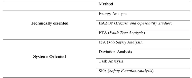
There are two main kinds of approaches in these methods (Table 2.4); the ones that are technically oriented and the systems oriented. The first ones aim to a systematic approach of risk and presuppose a good knowledge of the system and technology in study; the systems oriented consider the links between technical aspects, people and organization.
Table 2.4 - Some methods of Safety Analysis (adapted from Harms-Ringdahl, 2001, p. 41)
Method
Technically oriented
Energy Analysis
HAZOP (Hazard and Operability Studies)
FTA (Fault Tree Analysis)
Systems Oriented
JSA (Job Safety Analysis)
Deviation Analysis
Task Analysis
SFA (Safety Function Analysis)
It should be noted that currently there are a large number of methods available (e.g.: review of literature by Aven, 2009). However, this is a short review and only the most relevant will be summarized, especially those that are more frequently described and/or applied in the context of occupational risks on a day-to-day basis by many enterprises;
present in the installation that can, physically, biologically or chemically, harm a person when connected to a specific event.
The energy analysis is performed in four main steps:
1. Dividing the system into a number of parts, to be analyzed individually;
2. Identifying energies for each divided part, with the help of a structured checklist of energies;
3. Assessing the identified energy sources. This can be done in different ways, using different methods (i.e., complementary approaches);
4. Making proposals for improvements.
Its main advantages are an easy form of application and the systematic identification of energy barriers aiming prevention and protection.
According to Kletz (2001), the HAZOP was developed by ICI Petrochemicals Division in 1963, but it was first published only in 1974 by Herbert G. Lawley (cited by Harms-Ringdahl, 2001). Its main concept is a systematic and extensive search, using keywords in guidance, of deviations that can cause serious harm. It provides the opportunity for people to think of every possible ways in which hazards might arise, reducing the chance that something is missed. The characteristic elements of an HAZOP analysis are:
Intention – For each part of the installation, previously divided, is defined a specific intention.
Deviation – All the possible deviations from the normal functioning that can cause dangerous events.
Key-Word – Used to guide the search to identify the different types of deviations.
Team – The analysis is always executed by a team composed with specialists from different areas.
systems; provides an overview on how faults can lead to consequences and it is restricted to the identification of the system and component causes that lead to one particular top event. On the other hand, one important disadvantage is the requirement of expertise knowledge and training to execute it, once mistakes are difficult to find and the logic is difficult to follow.
When turning to the “systems oriented” methods, the JSA (Job Safety Analysis), focuses on human tasks. It analyses the tasks performed by a person or group of persons, and it is best fitted to use in well defined tasks and its sequences (e.g. automobile manufacturing lines, air controllers, etc.). The method was firstly approached and described by Grimaldi in 1947 (cited by Harms-Ringdahl, 2001).
Deviation Analysis was introduced by Urban Kjelén in 1970s in job analysis, and later in the 1980s, Harms-Ringdahl adapted it for risk assessment and analysis of production systems (Harms-Ringdahl, 2001). The aim of this method is to identify deviations that can cause an accident; the main idea of this is that deviations can represent an hazard. However, sometimes it happens to gather positive deviations, which increase safety conditions. It is important to identify these exceptions because they should be used later as a standard procedure (or a safer method of work).
Task Analysis is a methodology that can offer valuable support in assessing and controlling risks; it covers a range of human factors techniques aiming at what manual
workers and process operators do. There are “action oriented” approaches and cognitive
approaches (Harms-Ringdahl, 2001).
The SFA (Safety Function Analysis) method is based in the concept of safety functions, and it was developed by Harms-Ringdahl (Harms-Ringdahl, 2001, 2003a). The method is generic and it can be applied to several systems, having the general objective to identify and analyze safety functions involved in a specific event. However the evaluation of how well the safety functions work and suggestions for improvements or entering new safety functions, are also important aims within the spirit of SFA
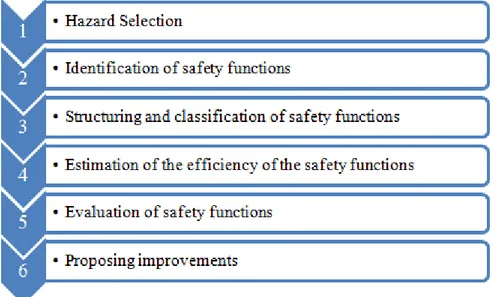
The analysis procedure has a set of stages, including a preparation phase and a concluding phase to report the results. However, there are six specific main stages:
1. Hazard Selection;
2. Identification of safety functions;
3. Structuring and classification of these functions; 4. Estimate the efficiency of the safety functions; 5. Assessing whether improvements are necessary; 6. Proposing improvements.
Since this method is the one used in the present study, it will be explained in more detail in the third chapter (Methodology).
2.2
EU Directives and practical/legal requirements
This section of the dissertation marks the transition to more practical issues, namely the
legal framework that is given by “Decreto-Lei n.º50/2005” referring to equipments, and
“Decreto-Lei n.º103/2008” referring to machinery. The legal requirements of each document above mentioned were converted into a check-list that was used as an aid during the analysis carried out within this work. The most relevant requirements of each law are summarized next.
Use of Equipment
The Decree DL 50/2005 from 25th February transposes into the Portuguese law the directive number 89/655/CEE, modified by directive number 95/63/CE and by directive number 2001/45/CE from the European council, related to the minimal prescriptions of safety and health for the use of equipment by workers. This is applied in all kind of industries.
resulting of equipment utilization (Art. 3.b). The proper maintenance of equipment during its utilization period must also be assured, so that they respect the minimum
safety requirements and don’t cause any hazard to workers safety and health (Art 3.e). This chapter also refers that the employers must proceed to periodic verifications and if necessary, essays of work equipment that is exposed to some influences causing deterioration and consequently possibility of risk. They must proceed also to extraordinary verifications of work equipment, when facing exceptional events or long periods of none utilization, that may have severe consequences for safety. These verifications and equipment essays above referred must always be executed by a qualified person, to ensure proper installation and good functioning (Art. 6).
Regarding work equipment involving specific risks, the employer must take special precautions so that the use of that equipment is only made by an operator qualified for the corresponding activity (Art. 5).
The employer must also give proper and easy understanding information, to workers and to the safety and health representatives, about the equipment used. That information must have indications of conditions for use of equipment, abnormal predictable situations, acquired experience from the use of equipment and possible due risks (Art. 8).
The second chapter, section II (DL 50/2005), establishes the minimum safety requirements for work equipment, applied to the extent that the corresponding risk exists in the work equipment in question. These minimum requirements are divided in articles, shortly described below.
Control Systems – must be plainly visible, identifiable and, if appropriate, have a proper markup. They also must be safe and choose regarding fails, predictable disturbances and limitations in the use for which they were designed (Art. 11).
Equipment Startup – A voluntary action must be applied over a control to start the equipments after a stop of any kind, unless the stop results of a normal sequence or an automatic work cycle (Art. 12).
equipment should be stopped whenever there is a stop of itself or its dangerous elements (Art. 13).
Stability and Rupture or disintegration of parts – The equipment as its respective elements must be stabilized by means of fixation or any other means whenever the safety of workers justifies it (Art. 14).
Projections and Fumes – The work equipments must have efficient retention or extraction devices located near the focus point (Art. 15).
Risk of Mechanical contact – The moving elements liable of causing accidents by mechanical contact must have protecting devices with robustness that stop the access to dangerous areas, or devices that interpose the movement of elements before they access those areas. They must be situated in a secure distance and must not limit the work cycle observation (Art. 16).
Illumination and Temperature – The equipment must be conveniently illuminated regarding the work to process. They also must be protected against the risk of contact or proximity with high or low temperature parts (Art. 17).
Warning Devices – They must be clearly heard and easily understood without ambiguity (Art. 18).
Equipment Maintenance – The maintenance operations must be done with the equipment stopped, when not possible, the necessary caution measures must be assured to execute such tasks. The maintenance manual must be updated (Art. 19).
Electric, fire and explosion risks – The equipment must protect the workers from direct or indirect contact with electricity, fire, overheat, gas release or explosion (Art. 20). Energy sources – The equipment must have devices that allow isolating themselves from their external energy sources, and in case of reconnection, this must be done with no harm for the workers (Art. 21).
Safety Signs – The equipment must be clearly signaled with warnings or other indispensable signals to guarantee the workers safety (Art. 22).
over, energy transmission, and forklift rollover risk. Finally, section IV (DL 50/2005) describes the additional requirements for lifting loads. Those equipments for such purpose, permanently installed, must maintain its robustness and stability during an action of lifting, taking into account what kind of loads are being lifted and the corresponding forces exercised in the suspension or fixation points. They must also be installed in such way to reduce the risk of collision with the workers, or the risk of balancing, tilt and fall unwittingly (Art. 27). Also, the lifting loads equipment must clearly indicate their nominal load and, if necessary, the nominal load for each machine configuration. The elevation accessories must have a sign that can identify their safety use, and if the equipment is not meant for workers elevation, it must have the proper prohibition sign within it (Art. 28). The rules for use of work equipment are also established in Chapter III.
Machinery
The Decree DL 103/2008 from 24th June, which regulates the placing on the market of machines, transposes to internal law the European Directive n.º 2006/42/CE; this decree clarifies a number of safety requirements concerning machines and machine components. It also introduces the concept of partly completed machinery and establishes rules for its allocation in the market.
The legal requirements apply to the following products:
Machinery;
Interchangeable equipment;
Safety components;
Lifting accessories;
Chains, ropes and webbing;
Removable mechanical transmission devices;
Partly completed machinery.
(a) "Machinery" means:
- an assembly, fitted with or intended to be fitted with a drive system other than directly applied human or animal effort, consisting of linked parts or components, at least one of which moves, and which are joined together for a specific application,
- an assembly referred to in the first indent, missing only the components to connect it on site or to sources of energy and motion,
- an assembly referred to in the first and second indents, ready to be installed and able to function as it stands only if mounted on a means of transport, or installed in a building or a structure,
- assemblies of machinery referred to in the first, second and third indents or partly completed machinery referred to in point (g) which, in order to achieve the same end, are arranged and controlled so that they function as an integral whole,
- an assembly of linked parts or components, at least one of which moves and which are joined together, intended for lifting loads and whose only power source is directly applied human effort;
(b) "interchangeable equipment" means a device which, after the putting into service of machinery or of a tractor, is assembled with that machinery or tractor by the operator himself in order to change its function or attribute a new function, in so far as this equipment is not a tool;
(c) "Safety component" means a component: - which serves to fulfill a safety function; - which is independently placed on the market;
- the failure and/or malfunction of which endangers the safety of persons;
- which is not necessary in order for the machinery to function, or for which normal components may be substituted in order for the machinery to function.
and which is independently placed on the market; slings and their components are also regarded as lifting accessories;
(e) "chains, ropes and webbing" means chains, ropes and webbing designed and constructed for lifting purposes as part of lifting machinery or lifting accessories;
(f) "Removable mechanical transmission device" means a removable component for transmitting power between self-propelled machinery or a tractor and another machine by joining them at the first fixed bearing. When it is placed on the market with the guard it shall be regarded as one product;
(g) "Partly completed machinery" means an assembly which is almost machinery but which cannot in itself perform a specific application. A drive system is partly completed machinery. Partly completed machinery is only intended to be incorporated into or assembled with other machinery or other partly completed machinery or equipment, thereby forming machinery to which this Directive applies.
Article 5, Freedom of movement refers that before imputing a machine to the market, the Member States shall not prohibit, restrict or impede the placing on the market and/or putting into service in their territory of machinery which complies with this Directive. Member States shall not prohibit, restrict or impede the placing on the market of partly completed machinery where the manufacturer or his authorized representative makes a declaration of incorporation, stating that it is to be incorporated into machinery or assembled with other partly completed machinery to form machinery. Still, at trade fairs, exhibitions, demonstrations, and such like, Member States shall not prevent the showing of machinery or partly completed machinery which does not conform to this Directive, provided that a visible sign clearly indicates that it does not conform and that it will not be made available until it has been brought into conformity. Furthermore, during demonstrations of such non-conforming machinery or partly completed machinery, adequate safety measures shall be taken to ensure the protection of persons.
2.3 Synthesis of chapter
Safety analysis is, on the other hand, a procedure to analyze systems, identify, and evaluate hazards and safety characteristics. One of the main concepts analyzed in this Chapter were barriers, which are reactive and proactive forms, however safety can’t be assured only by reacting, it must look to the future being proactive, yet it can happen that the required investment to prevent unwanted events can be a risk if nothing takes place in time.
3. Methodology
3.1
Introduction
The general methodology of this work is based in a case study approach with a timeline of about five months. The choice of the processes studied was based on the number and type of hazards identified previously by Renova: not only do they have more safety functions to assess, but also are the most hazardous.
The current study has applied the new modified version of Safety Function Analysis; the original version of SFA appeared in 2001 (Harms-Ringdahl, 2001; Harms-Ringdahl, 2003a), but Harms-Ringdahl has developed it further in May 2011 (Harms-Ringdahl, 2011). This new version will be commented and described below, explaining what changes in comparison with the previous version and why those changes were made. The author of this thesis spent a full-time week in a company of paper transformation called Renova, where he has made direct observation of the production processes. Furthermore, informal discussions with operators and line managers were also performed.
At first, this chapter will describe the risk assessment procedure currently used in the company for general application. Then the original version of the SFA method (Harms-Ringdahl, 2003) is explained. The chapter ends with the description of the modified version of SFA, where a flowchart is presented for a better understanding, with the main differences between the two versions of the method.
The study itself continues with the application of the above mentioned SFA approach, the discussion of the main results and the relevant conclusions, which are included within the subsequent chapters.
3.2
Risk Assessment
–
method currently used in Renova
The method used by Renova in risk assessment is a modified version of the well-known William T. Fine (Fine, 1971). This method starts with the evaluation of the working station, being necessary to compile all the important information, like legislation,
classification must take into account several risk factors, which may have a direct causal relationship with the possible accident. Table 3.1 shows a way to classify the level of deficiency.
Table 3.1 - Level of Deficiency classification (Renova, 2011; WTF modified)
Level of Deficiency (LD) Scale Definition; Descriptions
Acceptable 1
Deficient factors were not detected.
Risks are controlled.
Insufficient 2
Minor important deficient factors were detected
Existent preventive measures can be improved
Deficient 6
Significant deficient factors were detected
Some preventive existing measures are not quite efficient
Very Deficient 10
The preventive existing measures are not efficient
Hazard will be present in most circumstances
Totally Deficient 14
There are no preventive measures
There are no safety rules for the activity observed
Hazards associated with the activity are unknown
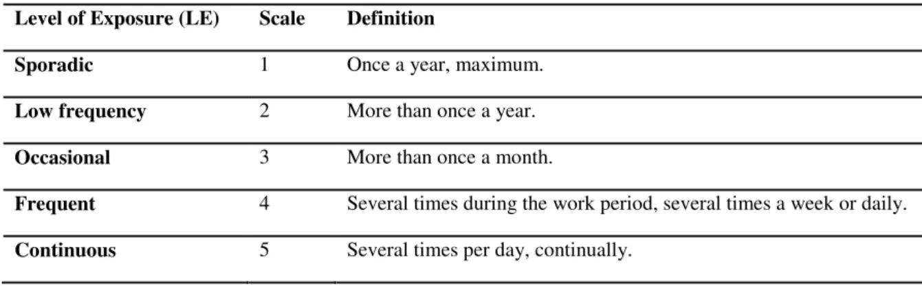
Another important factor is the level of exposure (LE), this factor indicates the frequency of exposure of a worker to hazards, estimated through the time of permanence in the workplace or machinery operations, etc. Table 3.2 shows the given scores to the level of exposure.
Table 3.2 - Level of exposure classification (Renova, 2011; WTF modified)
Level of Exposure (LE) Scale Definition
Sporadic 1 Once a year, maximum.
Low frequency 2 More than once a year.
Occasional 3 More than once a month.
Frequent 4 Several times during the work period, several times a week or daily.
The level of probability (LP) can be scored by the product of the level of deficiency (LD) and the level of exposure (LE). Table 3.3 shows the scale of this level.
Table 3.3 - Level of Probability (Renova, 2011; WTF modified)
(LP = LE x LD)
Level of Probability (LP) Scale
(Scoring) Definition
Very Low [1 – 3] The hazard situation is not expected to occur in the installation lifetime.
Low [4 – 6] The hazard situation may occur in the installation lifetime.
Medium [8 – 20] The hazard situation may occur in medium-term
High [24 – 30] The hazard situation may occur in short-term.
Very High [40 – 70] The hazard situation is almost certain to occur.
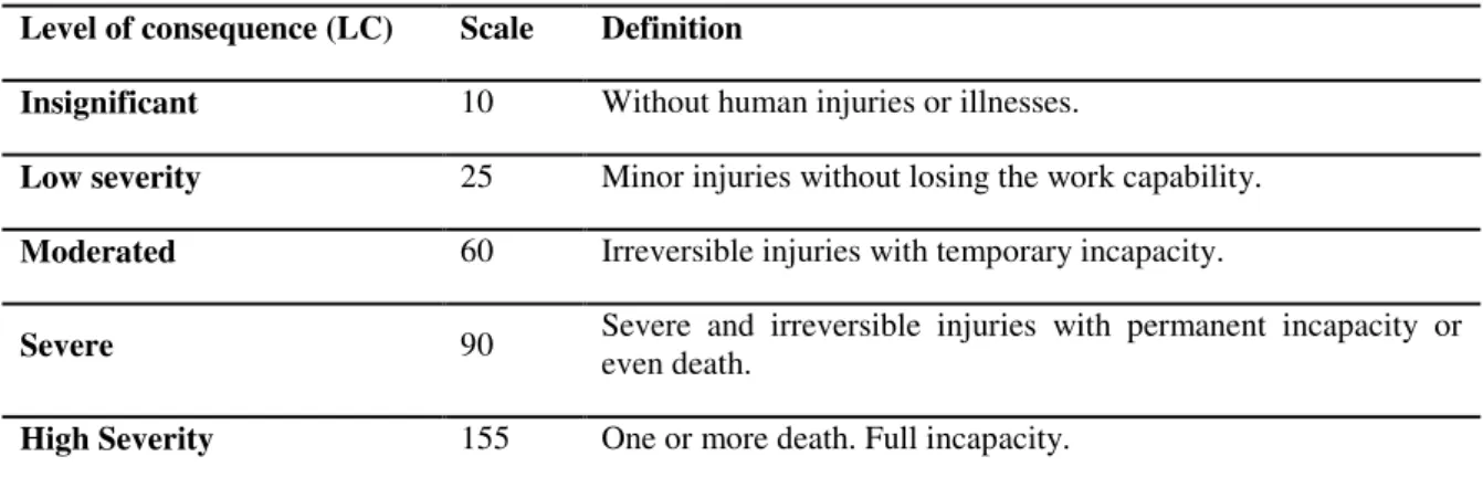
By definition, as also shown in Chapter 2, “risk” is the combination of the probability of
occurrence of an event and its injuries gravity (consequence). From the definition arises the term level of consequence (LC) which may be scaled as shown in table 3.4. The level of risk (LR) is the result of the product between the level of probability and the level of consequence. Table 3.5 shows the kind of control that must be followed according to the scored level of risk.
Table 3.4 - Level of Consequence (Renova, 2011; WTF modified)
Level of consequence (LC) Scale Definition
Insignificant 10 Without human injuries or illnesses.
Low severity 25 Minor injuries without losing the work capability.
Moderated 60 Irreversible injuries with temporary incapacity.
Severe 90 Severe and irreversible injuries with permanent incapacity or even death.
High Severity 155 One or more death. Full incapacity.
Table 3.5 - Level of Risk evaluation (Renova, 2011; WTF modified)
(LR = LP x LC)
Level of Risk (LR) Control
level Situation Measures
[3000 – 10850] I Critical
Immediate intervention;
Possible activity stop;
Isolate the hazard until measures are adopted.
[1250 – 3000] II To be corrected
Adopt alternative control measures, while the situation is not reduced or eliminated;
Plan improvements within short-term.
[360 – 1250] III To improve
Plan alternative forms of work execution;
Possible improvements of the existent conditions;
Create procedures of safety instructions for the activity.
[100 – 360] IV Controlled Act only if exists capacity and improvement opportunity.
[10 – 100] V No intervention
necessary Activity monitoring.
3.3
Safety Function Analysis (2001, 2003a)
The method SFA – Safety Function Analysis, is based on the concept of safety functions, and it was developed by Harms-Ringdahl in 2001. As already mentioned, the method is generic and it can be applied to several systems, having the general objective to identify and analyze safety functions involved in a specific event. However the evaluation of how well the safety functions work and suggestions for improvements or entering new safety functions, are also important aims to get in the SFA.
The analysis procedure has a set of stages, including a preparation phase and a concluding phase to report the results. However, there are six specific main stages, represented below (Figure 3.1).
Step 1 - Hazard Selection
The hazard selection can be done using any traditional method of risk analysis, as the ones described earlier in Chapter 2.1.3. From these methods the most significant hazards are chosen to be analyzed. The methodology used by Renova to identify the hazards and assess the risk level is W.T. FINE (modified). This approach was just described in the previous section.
Step 2 - Identification of Safety Functions
For the second stage, there are several ways to identify the safety functions; it can be
done using a structured “checklist” with a set of safety functions (EU-Agency, 2007), or identifying the ones that are relevant to the hazard analyzed. Other method is the use of documents reporting accidents where the analyst tries to identify statements or just simply words that can indicate a safety function; similar to a text analysis, this can be done through interviews and discussions with a group of people, where the analyst can
pick sentences or words that can be understood as safety functions when posing questions to the group about what started the accident or what could have been done to prevent it. Such questions should be of the following kind:
How to keep low the probability of the accident?
How to keep low the consequences of the accident?
How to reduce the accident seriousness if it happens?
In this work, the identification of safety functions was made with the help of an existent checklist created by Renova engineers, together with an extensive observation of the process performed by the author of this work and taking into account the present machinery and use of equipment legal requirements.
Step 3 - Structuring and classification of Safety Functions
In the third stage, the safety functions identified and generated in an arbitrary order are
structured into a logical way to facilitate their assessment. When structuring the SFs it might be useful to use the parameters described in Chapter 2.1.2 for defining a safety function:
Level of abstraction;
System level;
Type of safety function;
Intention of safety function.
The Level of abstraction is situated in the lower level of the concrete solution, e.g. a safety relay or a temperature guard. At higher levels it can refer to protection against excessive temperatures.
The System level is related with the hierarchy where the system is included. An example of a hierarchy division is referred by Harms-Ringdahl (2008) as component, subsystem, machine, department and factory.
The Intention of safety function characterizes the system to be protected; it might be a technical system, control room, etc.
However the safety functions can also be divided by selecting a few categories, depending on the results from the identification stage. They can be structured by type of safety function, such as technical, organizational or human, by organizational aspects (how the safety function is related to organizations to which they belong) or by accident sequence.
Based in the criteria used, each safety function is classified and ready to be sorted according to the classification made. After the sorting, the safety functions are in a better order, allowing the analyst to find identical or even repeated safety functions and correct them. The structuring step should be seen as an iterative process which creates an improved structure.
Step 4 – Estimation of the efficiency of the Safety Functions
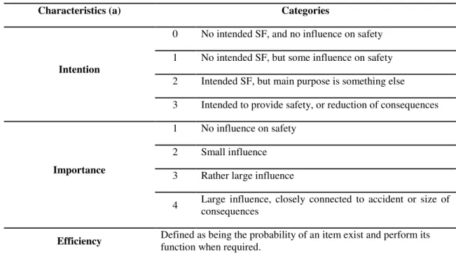
To estimate the efficiency of a safety function, in the fourth stage, one needs to evaluate it using a certain number of characteristics. According to Harms-Ringdahl (2001, 2003a), the characteristics shown in Table 3.6, and its categories, can be applied.
Table 3.6 - Categories of SF characteristics (Harms-Ringdahl, 2003a, p. 707)
Characteristics (a) Categories
Intention
0 No intended SF, and no influence on safety
1 No intended SF, but some influence on safety
2 Intended SF, but main purpose is something else
3 Intended to provide safety, or reduction of consequences
Importance
1 No influence on safety
2 Small influence
3 Rather large influence
4 Large influence, closely connected to accident or size of consequences
Efficiency Defined as being the probability of an item exist and perform its function when required.
The Intention of a safety function has its most importance at the design stage, when it is essential to define intentions according to different solutions. This can be divided into four categories shown in the table above.
Importance should assume that a safety function works as it should, reflecting its bigger or lower influence on safety. It is also divided and evaluated in four categories (Table 3.6).
Efficiency can be seen as a combination of reliability and the probability of the safety function to take place in time. The success rate is directly related to how the safety function works, the bigger the success rate is, the best work is performed by the SF. This rate ranges from 0% to 99,99%.
Step 5 – Evaluation of the safety functions
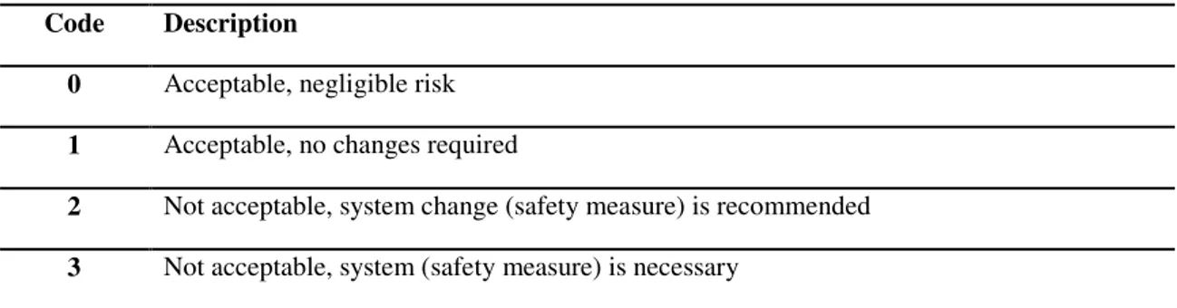
The next step is to assess the safety functions in a systematic and consistent way following a pre-defined scheme, judging either the function is acceptable offering enough safety to control the hazard, or if improvement is necessary. Harms-Ringdahl (2001, 2003a) uses a scale, represented on Table 3.7, to apply the judgment and establish any improvement measures if necessary. This decision about acceptability is made for each safety function taking into account the characteristics previously mentioned (Intention, Importance and Efficiency).
Table 3.7 - Scale to apply judgment of acceptability (Harms-Ringdahl, 2001, 2003a)
Code Description
0 Acceptable, negligible risk
1 Acceptable, no changes required
2 Not acceptable, system change (safety measure) is recommended
Step 6 - Proposing improvements
After deciding whether a safety function is acceptable or not, it might be necessary to
propose improvements, aiming to increase efficiency and/or to eliminate weak points. These improvements must be specific for each SF, and they must be ordered by priority, according to the analyst decision.
In this original version, however, there is no guidance on how to judge the several possible combinations of the criteria used, i.e., no instrument to achieve the final decision in an objective way. This limitation was probably not felt when using the method on the basis of a single case study, especially for research purposes. However,
the lack of a final guidance reduces “repeatability” when the method is applied on a
more routine basis by field professionals.
3.4
Safety Function Analysis (New development; Harms-Ringdahl, 2011
draft)
The flowchart depicted in figure 3.3 illustrates, in a simplified way, the main differences between the original SFA version of 2001 and the modified version proposed by Harms-Ringdahl in 2011. As it can be seen, the three first stages are the same for the two versions; the main differences only manifest in the next steps.
While the previous version of SFA splits the estimation of efficiency and evaluation in two different steps, the fourth step of the 2011 version aggregates them, and it is
renamed as “Evaluation of Safety Functions”. This stage turns out to be of great importance in the whole procedure, since this is where the safety functions are characterized and evaluated for necessary changes in the safety level.
2001, 2003a,b
2011 (
draft
)
Table 3.8 - Classification of Intention of Safety Functions (Harms-Ringdahl, 2011 draft, chapter 11)
Code Description
0 No intended safety function and no influence on safety.
1 No intended safety function, but influence on safety
2 Intended safety function, but main purpose is something else
3 Intended to provide a safety function
4 Intended to provide a safety function through a formal system
9 Uncertain intention
Importance maintains its four types of categorization; however the codes and descriptions had slightly changed (Table 3.9).
Table 3.9 - Classification of Importance of SF (Harms-Ringdahl, 2011 draft, chapter 11)
Code Description
0 SF has no or very small influence on safety
1 Small influence on safety
2 Rather large influence on safety
3 Large influence on safety
As for Efficiency, this characteristic is better defined using now new parameters to
identify efficiency, such as “probability to function” and “Error frequency”; the last one
Table 3.10 - Scale of efficiency for SF based on frequency of error or probability (Harms-Ringdahl, 2011 draft, chapter 11)
Code Efficiency Probability to function Error Frequency
0 Very Low < 50% -
1 Low > 50% < 100 times / year
2 Medium > 90% < 10 times / year
3 High > 99% < 1 time / year
4 Very High ≥ 99,99% < 0,01 time / year
Monitoring is a new characteristic included in the analysis, which evaluates the need for monitoring the safety functions and also their present performance. The efficiency of a safety function can get lower with time passing by, so this is a very important system
that helps to maintain the function’s performance. There are different levels of
monitoring, according to the status of performance. Table 3.11 shows the different status and the corresponding need (or no need) for monitoring. The monitor status is the most important attribute for the evaluation of the criterion “monitoring”.
Table 3.11 - Need of monitoring, and judgment of status (adapted from Harms-Ringdahl, 2011 draft, chapter 11)
Code Needs (requirements) Status Code
MN4 Monitoring is essential Meets the requirements MS2
MN3 Monitoring is necessary, at least periodically
Exists, but not fully meet the requirement
MS1
MN2 Monitoring is of interest, but not a critical issue
Monitoring function does not meet requirement
MS0
MN1 Of low interest Ok, no need for monitoring MS2
MN0 Not needed or irrelevant Ok, no need for monitoring MS2