1.Higher Institute for Applied Sciences and Technology – Department of Applied Physics – Damascus – Syria.
Correspondence author: Issam Elwan | Higher Institute for Applied Sciences and Technology – Department of Applied Physics | Damascus, P.O. Box 31983 | Barzah – Damascus – Syria | E-mail: [email protected]
Received: Jul. 13, 2017 | Accepted: Sept. 19, 2017 Section Editor: Melih Kushan
ABSTRACT:The present study investigates the influence of fiber content on thermal properties of short silica fiber (SSF) reinforced modified resole resin (MRR) composites. For this purpose, different SSF loading composites were prepared: 40, 55, and 65 wt.%. The ablation resistance related to mass loss parameters was quantified by testing under an oxyacetylene flame up to 2300 °C for 30 s. The thermal conductivity of the composite was studied via experimental steady state technique. Thermal stability of the composite material was estimated by means of thermo-gravimetric analysis (TGA), both in air and nitrogen atmosphere. The ablated composite material was characterized by different techniques (XRD, FTIR, and SEM). The results showed that the back-face surback-face temperature of SSF/MRR composites follows the typical variation curve, and linear ablation rate, mass ablation rate, and char yield decrease with increasing silica fiber content. This confirms that 55 and 65 wt.% SSF loading exhibited the best anti-ablation performance and the lowest percentage of char yield. XRD and FTIR analysis of the ablated specimen zone showed the absence of new phase. The thermo-gravimetric analysis confirmed the thermal resistance of SSF/MRR composites in comparison with MRR matrix and the decrease of char with increasing SSF loading. The thermal conductivity of these composites was significantly enhanced by the SSF into the modified resole matrix. This thermal conductivity follows both the rule of mixture and Maxwell models. The overall thermal characteristics of the SSF/MRR composites meet most of the necessary high temperature application criteria.
KEYWORDS: Ablation properties, Modified resole resin, Short silica fiber, Thermal conductivity.
INTRODUCTION
Fiber-reinforced composites have received much attention as ablative materials for aerospace applications in recent years (Eslami et al. 2015). The choice of reinforcing fiber and matrix depends upon various factors, among which strength, thermal stability, load bearing capability, and most importantly the type of envisaged application. Ablative composites are those materials that sacrifice themselves to protect the inner hardware during vehicles and spacecraft’s reentry from ultrahigh temperature and supersonic environments (Hu et al. 2014). The ablation of a material depends on its inherent properties and also on extrinsic conditions such as thermal, chemical, and mechanical factors related to theoretical or practical environment variables. When studying thermal behavior of phenolic-silica composites, it has to be noted that the most important subject is the decomposition
Preparation and Ablation Performance of
Lightweight Phenolic Composite Material
under Oxyacetylene Torch Environment
Issam Elwan1, Rafi Jabra1, Mohamed Hamzeh Arafeh1Elwan I; Jabra R; Arafeh MH (2018) Preparation and Ablation Performance of Lightweight Phenolic Composite Material under Oxyacetylene Torch Environment. J Aerosp Technol Manag, 10: e3118. doi: 10.5028/jatm.v10.935.
How to cite
Elwan I http://orcid.org/0000-0002-9647-9372
Jabra R http://orcid.org/0000-0003-0227-9263
behavior of the matrix, since reinforcing silica fibers have very much higher thermal stability than the polymeric matrix. Therefore, phenolic resins are considered among the best matrix for advanced composites providing the unbeatable combination of handling characteristics, processing flexibility, composite mechanical properties and acceptable cost. Resole type phenolic resin has attracted great scientific interest as it can be effectively used as a matrix system in ablation resistant composites due to its excellent erosion resistance and char retention capacities (Bahramanian et al. 2006). Its properties can be further improved by modification with different additives like polyvinyl butyral (PVB), which improves processability and toughness (Kang and Hwang 1996). Resole resin falls under the category of thermosetting ablators, which are also known as non-melting, char forming resins and possessing high heat of pyrolysis. Thus, during fire exposure, phenolic resin receives heat in the initial stage, decomposes to char and forms a thermal insulation layer. The large number of aromatic rings in the resole type phenolic resin leads to high carbon yield and the effective char formation ability (Mouritz and Gibson 2006). High char retention of the resole type phenolic resins makes them an effective candidate for ablative nozzle liner application (Nair 2004; Hu et al. 2014). To further increase the thermal stability of the composite, chopped silica fiber (SSF) was considered as reinforcing filler because of its high thermal resistance and melting temperature above 1700 °C. SSF has also a very low coefficient of thermal expansion (0.54 × 10⁻⁶ K–1) and low thermal conductivity
(0.65 W/m.K), which make it suitable for applications including ablators and thermal barriers (Wang et al. 2012; Shulock and Saffadi 1982).
Phenolic-silica composites are considered as one of the most important classes of ablative material of high temperature for high specific heat, low density, small ablation rate, and high rate of carbon conversion utilized more extensively in structure and ablation applications (Shi et al. 2015). When such an ablative material is subjected to high-heat flux, the phenolic resin within the composite will pyrolyze at first. As the pyrolysis proceeds, the decomposition zone will recess and penetrate the material (Shi et al. 2016a). The products of the pyrolysis are a mixture of gasses and residual char layer of carbon and silica mainly. If the heat flux is very large, the silica fiber will eventually melt forming liquid film covering some char surface. The pyrolysis gasses will then percolate through the char and bubble through the molten layer. In this process, complex post-pyrolytic chemical reactions may also take place. Near the surface of the molten layer, heterogeneous carbon-silica reactions may occur and molten silica may be subject to vaporization (Shi et al. 2016b; Hsieh and Seader 1973). In addition, the char plays an important role in ablation process by limiting oxygen diffusion from the boundary layer to the bulk and retarding exothermic degradation reactions of the polymeric matrix (Hsieh and Seader 1973). Torre et al., in their studies on a silica-based ablative composite, found that the char produced from the degradation of polymeric ablators was weak, brittle, and therefore, susceptible for rapid removal by the mechanical stresses due to the high vehicle speed, this phenomenon provokes the reduction of the thermal insulation (Torre et al. 2000; 1998a). Therefore, reinforcing fibers and other inorganic fillers must be included in the ablative formulation in order to improve the char stability and imparts mechanical strength to the char formed after the degradation of the polymer matrix. Shi et al. (2015) investigated thermal decomposition behavior of silica-phenolic composite by using solar radiant heating experiment with one-sided heat flux. They found that silica-phenolic composite exhibited an excellent thermal insulation during thermal exposure.
The aim of the present study was primarily to understand thermal and ablative properties under oxy-acetylene torch exposure environment of short silica fibers (SSF) modified resole resin (MRR) composites with different percentage of random SSF prepared by hot pressing technique. The effect of SSF concentration on the thermal decomposition/ablation and back-face temperature elevation of SSF/MRR composites are herein investigated. Ablation characteristics of SSF/MRR composites were studied by scanning electron microscopy (SEM), X-Ray diffraction (XRD), and FTIR spectroscopy.
MATERIALS AND METHODS
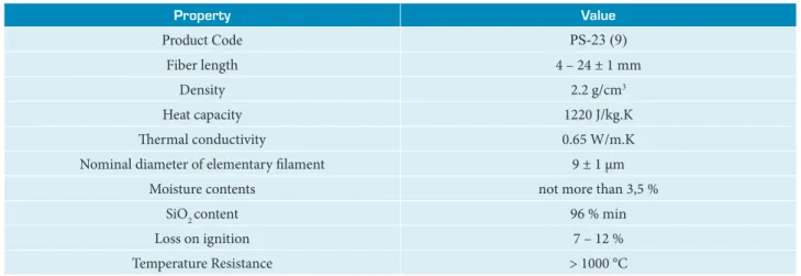
improving the toughness of resole resin. Silicon spray lubricant (WD40) was used to facilitate specimen de-molding. Chopped silica fibers manufactured by JSC Polotsk-Steklovolokno, Republic of Belarus, under the trade name PS-23 (9) were used as reinforcement material and their properties are shown in Table 1. The ammonia type resole phenolic resin was synthesized in the authors’ laboratory.
Table 1. Physical properties of chopped silica fiber.
Property Value
Product Code PS-23 (9)
Fiber length 4 – 24 ± 1 mm
Density 2.2 g/cm3
Heat capacity 1220 J/kg.K
Thermal conductivity 0.65 W/m.K
Nominal diameter of elementary filament 9 ± 1 µm
Moisture contents not more than 3,5 %
SiO2 content 96 % min
Loss on ignition 7 – 12 %
Temperature Resistance > 1000 °C
PREPARATION OF AMMONIA TYPE RESOLE PHENOLIC RESIN
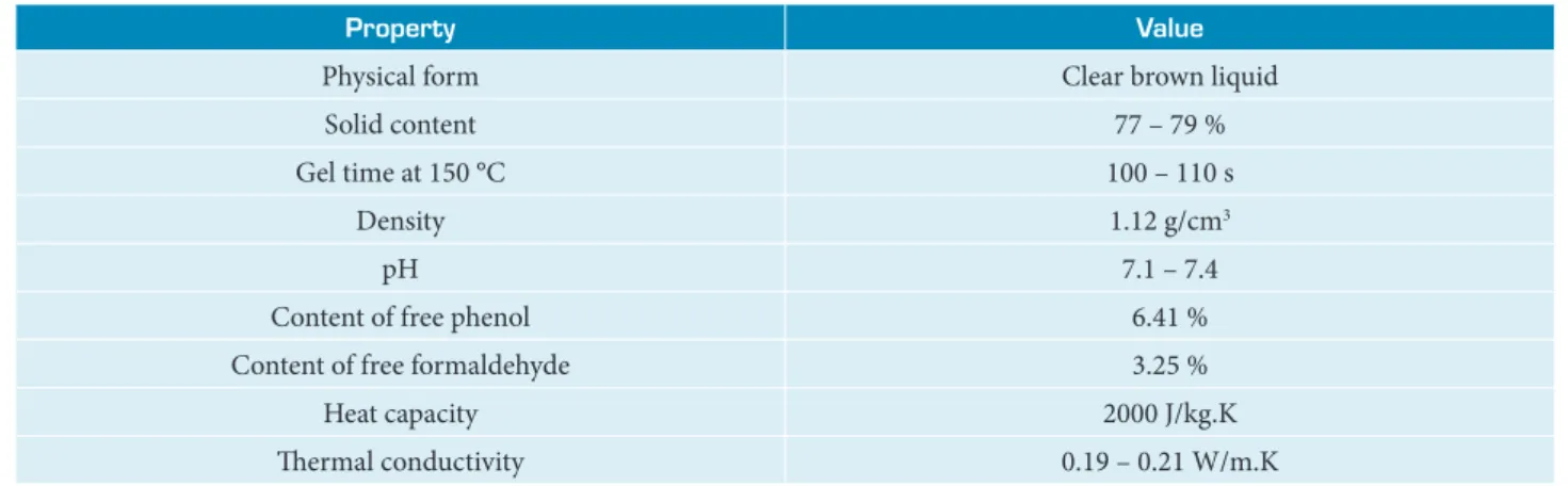
Resoles are phenol-formaldehyde condensation products with methylol groups and final cured structure with a random three-dimensional network of aromatic rings. Resole type thermoset was synthesized via polymerization of phenol and formaldehyde using NH4OH as a catalyst (Shafizadeh et al. 1999). Formaldehyde (F) and phenol (P) were mixed in the molar ratio of F/P = 1.25 with 0.15 mole catalyst. Four necks round bottom flask equipped with mechanical stirrer, temperature controller, and condenser was charged with 1 mole of phenol, 1.25 mole of 37% aqueous formaldehyde solution and 5.25 g of ammonia solution which was added dropwise giving a complex 3-D network. The solution was stirred and refluxed for 75 min at 85 °C. Then pH value was adjusted to 6 – 7 by the addition of 5% sulfuric acid solution. The aqueous phase was decanted, and the rest of water was removed by distillation under reduced pressure for about 3 h at 60 °C. Figure 1 shows the condensation reaction of ammonia resole resin. The physical properties of prepared ammonia resole resin are tabulated in Table 2.
Figure 1. Schematic reaction mechanisms for resole resin condensation (Pilato 2010).
Chain growth
As demonstrated in Fig. 1, the condensation reaction result is mostly resole resin, water and formaldehyde.
Table 2. Physical properties of synthesized resole resin type ammonia.
Property Value
Physical form Clear brown liquid
Solid content 77 – 79 %
Gel time at 150 °C 100 – 110 s
Density 1.12 g/cm3
pH 7.1 – 7.4
Content of free phenol 6.41 %
Content of free formaldehyde 3.25 %
Heat capacity 2000 J/kg.K
Thermal conductivity 0.19 – 0.21 W/m.K
IMPREGNATION SOLUTION PREPARATION
First of all, the solid content of prepared phenolic resole resin was adjusted to be 50 wt.% using absolute ethanol. Then, it was blended with PVB at a level of 15 parts per hundred weights of resin (phr) using absolute ethanol as common solvent. Blending was done using laboratory mixer (G-250 Laboratory Mixer) at 30 °C and stirrer speed of 200 rpm for 2 h. Then, 2 wt.% zinc stearate as release agent was added to the solution under mixing for additional 20 min at room temperature. The viscosity of the impregnation solution was measured using Ford cup Ø4 and adjusted using absolute ethanol to be 40 – 50 s.
PREPARATION OF COMPOSITE SPECIMENS
CHARACTERIZATION
ABLATION TESTING, BACK-FACE TEMPERATURE EVALUATION AND INSULATION INDEX
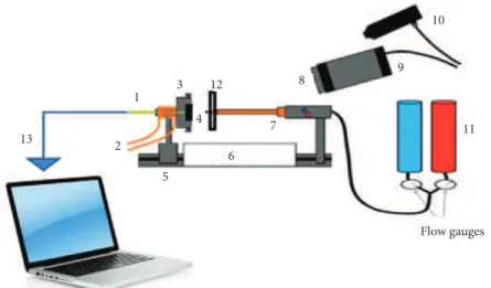
To study the ablation behavior of the composites, the severe hyperthermia environment was simulated by the oxyacetylene torch test according to ASTM E285-80 standard. A mixture of oxygen and acetylene was fired and used as the heat source of the experimental platform for ablation. Plate test specimens were of 100 × 100 mm in size and 7 mm in thickness. The nozzle diameter of the torch was 2 mm. The distance and the angle between the specimen surface and the torch tip were 20 mm and 90°, respectively. One K-type thermocouple was firmly attached at the center of the back-face of the specimen to record continuously temperature changes as a function of time during ablation test. This temperature sensing device was connected to the data logger laptop. The flow rates of oxygen and acetylene were 1.36 m3/h and 1.04 m3/h, respectively, which generated a flame temperature
of around 2400 °C during the test. This device is able to produce a high-temperature flame of approximately 3000 °C and high heat flux of about 820 W/cm2. A schematic of the torch test facility is shown in Fig. 3.
Figure 2. Molding and cure cycle procedure for SSF/MRR composites.
Figure 3. Oxyacetylene torch apparatus used for composite ablation: (1) back face thermocouple; (2) water cooling system; (3) specimen holder; (4) specimen; (5) specimen guide; (6) protective insulation; (7) oxyacetylene torch; (8) neutral filter;
(9) thermal imaging camera; (10) pyrometer; (11) gas cylinders; (12) thermal barrier; and (13) data logger laptop.
Prior to the ablation test, the samples were machined and grounded so as to obtain high parallel surfaces between the top and the bottom. Sample thickness was monitored using digital gauge disc caliper micrometer. The ablation test was continuously performed until the specimen was burnt through its entire thickness during a defined time to calculate insulation index and
T
emp
er
at
u
re
(
oC)
Time (min)
0 25 50
30
30 160
160
130 130
150
120
90
60
30
0
75 100 125 150 175
13
1 3
5
6 7 4
8 9
10
11
Flow gauges 12
erosion rate. In order to measure the linear and mass ablation rates, samples were held for 30 s and then the flame was extinguished allowing the samples to cool down naturally. The thickness and mass changes of all samples during the test were divided into the exposure time. The linear (LAR) mass (MAR) ablation rates, insulation index (IT), and percentage char yield were calculated according to the Eqs. 1-4.
where: T0, M0, T1 and M1 are the thickness and mass of the ablator specimen before and after ablation testing, respectively; t is the ablation time fixed at 30 s; and tT is the burn-through time (s) representing the time required to completely pierce the specimen. The schematic illustration for calculating linear ablation rate is presented in Fig. 4. Thickness measurements of ablated samples (T1) were done using the same digital gauge disc caliper micrometer.
Mass ablation rate (MAR) (g/s) = M0 M1 t
-t
é - ù
´
ê ú
ë û
Linear ablation rate (LAR) (mm/s) =
T
0T
1t
-Insulation index (s/m) =
-0
T T
t
I
T
=
é - ù
´
ê ú
ë û
% Char yield =
-0 1
0
100
M M
M
é - ù
´
ê ú
ë û
(1)
(3) (2)
(4)
Figure 4. Scheme for calculating linear ablation rate.
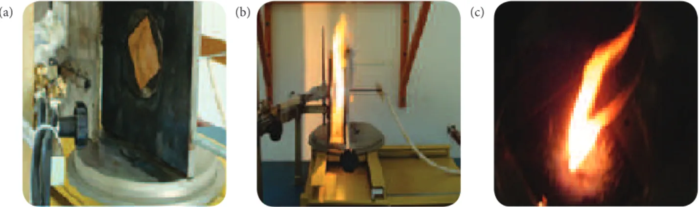
Figure 5 shows the images of one of the composite samples taken during the oxyacetylene torch testing and immediately after extinguishing the flame. Flame zones, namely primary flame zone and reflected flame zone, cover the entire surface area of the specimen. It is a very aggressive test because it involves high-temperature, high-velocity gas flow, and oxidizing gases.
Figure 5. Oxyacetylene test: (a) sample placed over a steel platform; (b) testing under an oxyacetylene flame at 20 mm from the nozzle; and (c) sample just after ablation.
T0
T1
(c) (b)
ABLATED COMPOSITE X-RAY DIFFRACTION ANALYSIS
Carbonized SSF/MRR composites were analyzed by X-Ray diffraction (XRD). The XRD characterization was performed using a classical diffractometer Philip PW 3710, type Bragg-Brentano θ-2θ, with negligible instrumental broadening using Cu Kα radiation (λ = 0.15406 nm) in the range 2θ = 10° – 80°, using a step size of 0.02, 40 kV and 30 mA.
ABLATED COMPOSITE FTIR SPECTROSCOPY ANALYSIS
Different functional groups and structural features of carbonized SSF/MRR composites were identified using FTIR spectroscopy. Studies were carried out using a Bruker Vector 22 FTIR Spectrometer with a standard DTGS and KBr window. Spectra were recorded in a range of 4500 – 400 cm–1, with a resolution better than 1 cm−1. The spectra of testing samples
were produced at room temperature using a transmission technique with KBr pellet.
COMPOSITE AND MODIFIED RESOLE RESIN THERMO-GRAVIMETRIC ANALYSIS
The thermal decomposition is defined by the American Society for Testing and Materials (ASTM) as “a process of extensive chemical species change caused by heat”, it involves physical as well as chemical processes. The physical processes entail charring, decomposition change and burning characteristics of the material, whilst chemical processes are responsible for the generation of flammable volatiles (Wilkie and Morgan 2009). Thermal stability of SSF/MRR composites and matrix carbonization with respect to temperature were evaluated using a thermo-gravimetric analyzer (TGA) (SETARAM LABSYS evo TGA 1150 Instruments, France) as per ASTM E1868. Samples of 10 – 20 mg were heated from 30 °C to 1100 °C at a heating rate of 10 °C/min. The TGA tests were performed in normal atmosphere environments and in nitrogen (N2) separately. According to the initial sample weight and degradation temperature, sample percentage char was recorded.
COMPOSITES THERMAL CONDUCTIVITY TEST
Thermal conductivity (λ) is defined as the ability of the material to transmit heat, it is measured in watts per square meter of surface area for a temperature gradient of 1 K per unit thickness of 1 m. The thermal conductivity is not always constant. The main factors affecting thermal conductivity are the material density and moisture and the test temperature. With increasing density, moisture and temperature, the thermal conductivity also increases (Chen et al. 2016). Measurement of thermal conductivity was performed by utilizing the thermal conductivity meter DTC-25 (TA Instruments, USA) for quick determination of thermal conductivity of solid materials using the guarded heat flow method. The TA Instruments DTC-25 thermal conductivity meters measures thermal conductivity according to the ASTM E1530 guarded heat flow meter method. In this technique, a sample of the material with 50 mm in diameter and 5 mm in thickness is held under a compressive load between two surfaces, each controlled at a different temperature. The lower surface is part of a calibrated heat flux transducer. As heat is transferred from the upper surface through the sample to the lower surface, an axial temperature gradient is established in the stack. By measuring the temperature difference across the sample along with the output from the heat flux transducer, thermal conductivity of the sample can be determined when the thickness is known. Knowing the values of supplying heat, temperatures and thickness, the thermal conductivity is determined by employing one-dimensional Fourier’s conduction law (Eq. 5). All measurements were performed at 30 ± 1 °C.
λ
dT
Q A
dx
l
=- (5)
where: Q is the heat flow conduction rate (W); λ is the thermal conductivity of the specimen (W/m.K); A is the cross-sectional area normal to heat flow direction (m2); and dT/dx is the temperature gradient (K/m) determined from the plotted graph of
MODELING OF COMPOSITE THERMAL CONDUCTIVITY
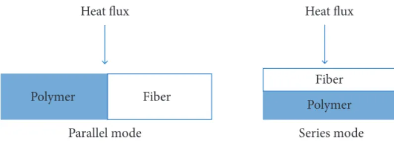
Thermal conductivity is a bulk property. Estimation of thermal conductivity of short fiber composites has been the subject of numerous analytical and empirical models, but none of them appears to characterize all types of composites (Fu and Mai 2003). In this paper, the review of thermal conductivity analytical models of composite materials is out of scope, but the focus was directed to one analytical model that is widely used in literature for comparison with experimental data. For a two component composite material, the simplest alternative would be to consider the material arranged either in parallel or in series with respect to the heat flow direction (Fig. 6), this leads to the upper and lower bounds of the effective thermal conductivity. In this study, we found that our experimental results could fit remarkably with models such as the rule of mixture one (Eq. 6) and the Maxwell’s model (Eq. 7) (Chikhi et al. 2011), which describe very well the conductivity of randomly distributed and non-interacting homogeneous spheres in a homogeneous medium.
λ λ
(1 )
n n n
f f f m
V V
l = l + - l
l l l l
l l
l l l l
é - - ù
ê - ú
ë û
λ λ
l l - l
(
)
(
)
2 2
2 2
m f m f f m
m f m f f V
V
l l l l
l l
l l l l
é + - - ù
= ê ú
+ +
-ë û
(6)
(7)
where: n = 1 for parallel conduction model; n = –1 for series conduction model; Vf is the volume fraction of fiber; λf and λm are thermal conductivity of fiber and matrix, respectively.
We will see that our experimental points could adapt very well with such models better than other models like Russell’s (Shen et al. 2011). However, the series model seems to be in excellent agreement with experimental data as compared to the parallel model (Bigg 1986). This is because the fibers are gathered in the polymer to form a conductive block of polymer whose alignment is parallel to the direction of thermal flux (parallel conduction). On the other hand, if the alignment of the conductive block of the polymer is perpendicular to the direction of thermal flux, the thermal conductivity will be the lowest (series conduction).
Figure 6. Representation of heat flow in composite materials.
ABLATED COMPOSITES SCANNING ELECTRON MICROSCOPY (SEM) EXAMINATION
The morphology behavior of the ablated composites was observed using VEGA II XMU SEM (TESCAN Company, USA) scanning electron microscopy (SEM). Specimens were sputter-coated with a gold layer before the examination, and the morphology micrographs of the composites were obtained.
RESULTS AND DISCUSSION
BACK-FACE TEMPERATURE PROGRESSION (BTP) OF ABLATED COMPOSITE AND VISUAL INSPECTION Figure 7 shows the temperature variation at the back surface of (a) 40 wt.%, (b) 55 wt.%, and (c) 65 wt.% SSF/MRR composites. These temperature variation curves were measured experimentally by the oxyacetylene flame test with heat flux of about 820 W/cm2. Temperature recording time was 77 s (30 s exposure time + 47 s post exposure time). At the end of the exposure
time, the back surface temperature of a 7 mm thickness 40 wt.%, 55 wt.%, and 65 wt.% composites were 263.09 °C, 67.38 °C, and
Heat flux
Parallel mode Series mode Fiber
Fiber Polymer
42.77 °C, respectively. These results show that the back surface temperature of 40 wt.% composite specimens, for example, is about 6 times and 4 times higher than those of 65 wt.% and 55 wt.% composite specimens, respectively. It can be observed from Fig. 7 that 55 wt.% and 65 wt.% composites behave thermally similarly until 40 s (30 s + 10 s) of flame test. After that, the maximum back-face temperatures of 40 wt.%, 55 wt.% and 65 wt.% composite specimens reach maximum values of 293 °C, 295.9 °C, and 288.3 °C at the 40.5th s, 65.8th s, and 72nd s, respectively. It is observed that BTP was reduced with increasing SSF loading in the
SSF/MRR composites. Considering a random distribution for both fiber lengths and fiber orientations (morphology analysis paragraph), it can be concluded that the augmentation of silica fiber fraction to a certain limit in MRR matrix has improved the thermal insulation of SSF/MRR composites with low fiber loading. On pyrolysis, the glassy char layer formed from MRR matrix builds up in the front, forms a protective layer and restricts heat transfer into the material impeding oxygen diffusion into the material. On the other hand, the incorporation of SSF in MRR matrix may act as a heat dissipater or as a much better network for transferring heat in a random manner. Hence, the fiber network will actually act as an additional heat barrier allowing SSF composites to exhibit superior integrity, which is advantageous for the performance of the composite as an ablative thermal protection system (Najim et al. 2008).
Figure 7. Back-face surface temperature profiles of SSF/MRR composites (a) 40 wt.%, (b) 55 wt.%, and (c) 65wt. % SSF after 30 s exposure to an oxyacetylene flame at 20 mm distance from the nozzle and 820 W/cm2 heat flux.
ABLATED COMPOSITE PERFORMANCE AND CHAR YIELD PERCENTAGE
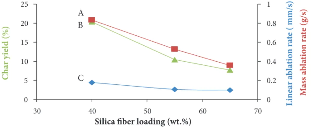
The geometric form and orientation of the SSF were considered to be randomly distributed. The determination of the SSF/MRR composites erosion rate is generally based on a simplifying assumption that all the SSF in the composite are laid in the same direction (Ommati et al. 2011). The ablation properties results of SSF/MRR composites are summarized in Table 3. The LAR, MAR, Insulation index and the char yield of the ablated composite specimens were measured using Eqs. 1-4 respectively and plotted in Fig. 8.
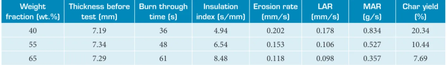
Table 3. Ablation properties of SSF/MRR composites as a function of silica fiber weight fraction.
Weight fraction (wt.%)
Thickness before test (mm)
Burn through time (s)
Insulation index (s/mm)
Erosion rate (mm/s)
LAR (mm/s)
MAR (g/s)
Char yield (%)
40 7.19 36 4.94 0.202 0.178 0.834 20.34
55 7.34 48 6.54 0.153 0.106 0.527 10.44
65 7.29 61 8.48 0.118 0.098 0.357 7.69
Figure 8 illustrates that the increase of silica fiber fraction in the composite leads to the gradual decrease of linear and mass ablation rates. LAR decreases from 0.178 to 0.098 mm/s when the silica fiber fraction increases from 40 to 65 wt.%, respectively (Fig. 8). The same observation can be seen for MAR. This result is in line with the findings of Qiu et al. (2005) in their investigation
0 50 100 150 200 250 300
40 wt.%
55 wt.%
65 wt.% (a)
(b) (c)
0 10 20 30 40 50 60 70 80
Time (s)
Back-f
ac
e t
em
p
er
at
ur
e (
on ablation performance of boron-modified phenolic resin (BPR) with high silica fiber composites. Moreover, the Char yield curve exhibits the same behavior as LAR. The high char yield value for the 40 wt.% SSF composite is mainly due to the higher MRR matrix amount of this material compared with the 65 wt.% SSF. In addition, as can be seen in Table 3, increasing silica fiber contents in composite leads to decreasing its erosion rate from 0.202 to 0.118 mm/s when silica fiber fraction increases from 40 to 65 wt.%, respectively. Conversely, when silica fiber content in the composite increases, the insulation index increases gradually.
Figure 8. (A) Mass ablation rate; (B) char yield; and (C) linear ablation rate of the ablated composites at different silica fiber loading.
0 0.2 0.4 0.6 0.8 1 0 5 10 15 20 25
30 40 50 60 70 L
ine ar a b la ti o n r at
e ( mm/s)
M ass a b la ti o n r at e (g/s) C ha r y ie ld (%)
Silica fiber loading (wt.%)
A
C B
From Table 3 and Fig. 8, it can be concluded that the incorporation of SSF in the MRR matrix enhances the ablation performance. This may be explained on the basis of the thermal diffusivity α (m2/s) = λ/ρ.C
p, where ρ (Kg/m
3) is the density and C
p (J/Kg.K) is
the specific heat of the composite; i.e., the smaller α, the better the heat insulation. For low values of material density ρ and thermal conductivity λ, α increases with decreasing Cp value (Qinghua 1992). Compared with other studies (Najim et al. 2008), we could say that SSF/MRR composites are exhibiting better insulation than (difurfurylideneacetone (DFA) -resole)/short fiberglass composites.
ABLATED COMPOSITE X-RAY DIFFRACTION PATTERN
The phase structure of ablated SSF/MRR composites has been examined by XRD. Figure 9 gives typical XRD pattern of one ablated composite. A broadband centered at 2θ = 26.45° (3.35 A°) is related to graphite’s basal plane (Foley et al. 2002) and another lower intensity peak with a maximum at 2θ = 21.42° (4.15 A°) is assigned to amorphous silica (Scian and Volzone 2001). This confirms that, under the performed test conditions, no changes in phase happened after pyrolysis of the SSF/MRR composites since no peaks related to α-cristobalite neither carbon- silica reaction was recognized in the XRD of ablated SSF/MRR composites.
Figure 9. XRD diffractogram of ablated composite.
FTIR ANALYSIS OF ABLATED COMPOSITE
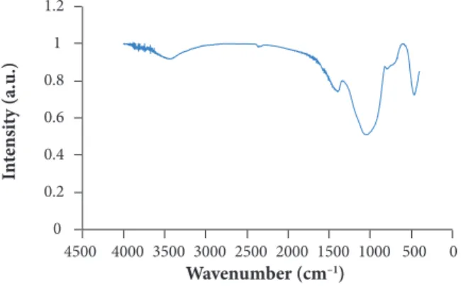
FTIR spectra of carbonized SSF/MRR composite shows four bands as demonstrated in Fig. 10. The band at 465 cm–1 belongs to
bending vibration of O-Si-O. The bands from 1090 cm–1 to 1100 cm–1, and from 775 cm–1 to 835 cm–1 belong to O-Si-O stretching
10 20
2θ(o)
In te ns it y (a.u .) 20 0 40 60 80
vibrations. The broadband around 3550 cm–1 is related to the absorption of Si-OH group, Si-O-Si asymmetrical transversal
stretching and surface hydroxyl groups, respectively (Ceballos-Mendivil et al. 2014). It is known that all organic materials spectra have small peaks at around 2300 – 2400 cm–1 which are related to the effect of C = N, C = O and N = O double bond stretching
vibration (Griffiths and Homes 2002).
Figure 10. FTIR spectra of ablated SSF/MRR composite.
THERMO-GRAVIMETRIC ANALYSIS
The thermal decomposition behavior of phenolic resins has been studied extensively because of the usage of phenolic matrix composites in high-temperature applications and fire resistant components. One method to reduce the flammability of composites is the addition of inert fillers like silica fiber to the polymer matrix (Lochte et al. 1965). TGA curves of MRR matrix, resole resin, and SSF/MRR composite are presented in Figs. 11 and 12, respectively. The general shapes of the three curves are nearly similar. The chemical changes of MRR matrix, resole resin and SSF/MRR composite exhibit a three-stage decomposition behavior that is indicative of a multiple-order decomposition process.
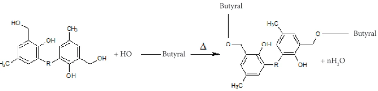
Firstly, a small loss in mass between (100 °C ~ 300 °C) is observed for MRR, resole resin and SSF/MRR composites. This could be attributed to the loss of water resulting from the post curing of phenolic resin during TGA test. At this stage, the polymer network remains highly undamaged and a random three-dimensional network of aromatic rings is obtained through continued condensation of hydroxyl-methyl groups and etherification reaction due to PVB incorporation in the resole resin as illustrated in Fig. 13. This could also lead to increasing the final crosslinking density of resole resin. The total weight loss at this stage is about 2%.
In the second stage and as the temperature increases between (300 °C ~ 650 °C), the MRR matrix, resole resin and SSF/MRR composites undergo thermal degradation and decomposition by scission reactions and formation of phenol, cresols and xylenols resulting from the scission of terminal benzene rings that depend on its position (Trick and Saliba 1995). These reactions are partially oxidative in nature, and the resin itself can act as an oxygen source. The weight loss of MRR matrix, resole resin and SSF/MRR composite at this stage is 39%, 23%, and 16%, respectively. The difference between resole resin and PVB modified resole resin matrix is quite clear in the difference between their weight losses at this second stage. This difference translating the PVB fraction (15 phr) seems not seriously affecting thermal stability of MRR matrix.
The final stage involves further conversion of aromatic rings into a carbonaceous char, with some further evolution of volatiles such as H2, CO, and CH4. In this stage, the aromatic rings of MRR turn into carbonized char by dehydrogenation and hydrogen transfer reaction and the weight loss of MRR matrix, resole resin and SSF/MRR composite is 60%, 60%, and 26%, respectively. These weight losses could be attributed to bulk degradation of modified phenolic resole resin matrix (Kim et al. 2016). Above 1000 °C, no significant increase in mass loss is observed because all phenolic resin in the composite has been carbonized and SSF/MRR composite residue reaches 74% approximately at 1150 °C. It is evident that silica fibers induce high effect on SSF/MRR composite char yield and improve thermal stability of MRR matrix (the final weight loss of MRR matrix and SSF/MRR composite are 60% and 26%, respectively).
0 0.2 0.4 0.6 0.8 1 1.2
0 500 1000 1500 2000 2500 3000 3500 4000 4500
In
te
ns
it
y (a.u
.)
Figure 13. Schematic reaction between PVB and resole resin (Ismail et al. 2009). Figure 11. TGA curves of (a) resole resin and (b) MRR matrix in flowing nitrogen (10 °C/min).
–70 –60 –50 –40 –30 –20 –10 0 10
100
0 200 300 400 500 600 700 800 900
W
eig
h
t l
oss (%)
Temperature (oC)
Resole resin (a) MRR (b)
Step 1: Volatilization of water and unreacted species
Step 2: Decomposition and rando chain scission of main chains
Step 3: Char formation
MRR and Resole resin Heating rate 10ºC/min
–40 –35 –30 –25 –20 –15 –10 –5 0 5
0 200 400 600 800 1000 1200 1400
W
eig
h
t l
oss (%)
Temperature (oC) Step 1: Volatilization of water and unreacted species
Step 2: Decomposition and random chain scission of main chains
SSF/MRR composites Heating rate 10 oC/min
Step 3: Char formation
(b) (a)
Butyral
Butyral
Butyral
+ nH2O + HO
Figure 14. Schematic representation of the suggested structure for fully carbonized phenolic resin with highly cross-linked glassy network.
The simplified illustration of the carbonized structure is represented in Fig. 14. As long as SSF does not decompose at the temperature under test, only modified phenolic resole resin is fully carbonized and transformed into char via dehydrogenation and condensation reactions. Due to the matrix high aromatic content, the yield of flammable volatiles is lower compared to many other polymers, enhancing the superior fire performance and low flammability of phenolic composites (Mouritz and Gibson 2006).
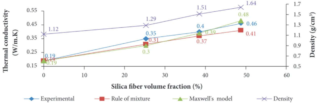
Figure 15. Variation of thermal conductivity and density with SSF volume fraction in SSF/MRR composites. THERMAL CONDUCTIVITY MEASUREMENT
At a specified temperature, the thermal conductivity of fiber reinforced polymer composite materials depends on the properties of the constituents at this temperature as well as their content. As a result, if the temperature-dependent thermal conductivity is known for both fibers and resin, the property of the composite material can be estimated. Thermal conductivities (TC) and densities of SSF/MRR composites at 30 °C are presented in Fig. 15.
The density of SSF/MRR composites increases with increasing fiber loading, the higher density value of 1.64 g/cm3 remains
within the reasonable interval of light-weight materials. On the other hand, the thermal conductivity of SSF/MRR composites increases with increasing density and fiber loading. The results show that adding 65 wt.% of silica fiber to MRR increased the thermal conductivity from 0.19 W/m.K to 0.46 W/m.K. It is also seen that composite thermal conductivity and density of composites linearly increase with SSF volume fraction. This is because both thermal conductivity and density of SSF (0.65 W/m.K and 2.2 g/cm3, respectively) are higher than those of MRR (0.19 W/m.K and 1.12 g/cm3, respectively). This could be attributed to the fact
that fibers form growing conductive paths in the polymer matrix and increase the thermal conductivity of SSF/MRR composites.
+ H2
0.5 0.7 0.9 1.1 1.3 1.5 1.7
0.15
0 10 20 30 40 50 60
0.25 0.35 0.45 0.55
1.12
1.29
1.51 1.64
0.48
0.39
0.3 0.35
0.46 0.4
0.41 0.37
0.31
0.19 0.19
0.19 D
ens
it
y (g/cm
3)
The
rma
l c
o
nd
u
ct
iv
it
y
(W/m.K)
Silica fiber volume fraction (%)
On the other hand, good distribution of SSF in the composite leads to good thermal dispersion of conducting paths. Figure 15 shows a good agreement between thermal conductivity experimental results and both rule of mixture and Maxwell’s models for the prediction of thermal conductivity of similar composite materials. The much lower conductivities of the silica phenolic composites are the result of the ceramic insulating characteristics of these fibers and the dominant heat transfer through phonons rather than free electrons. Generally, most metal oxide fillers such as alumina (Al2O3) and silica (SiO2) have a lower TC (Chen et al. 2016; Mottram and Taylor 1987). It should be noted that increasing filler loading level is not always preferred, as it can cause composite embrittlement, poor processability and high cost (Chen et al. 2016). Arambakam et al. (2013) found that fiber type, fiber volume fraction, fiber diameter, intrinsic thermal conductivity and fibers’ through-plane orientations have significant impacts on the heat conduction of fibrous composite materials. Fu and Mai (2003) also studied the effects of fiber volume fraction, fiber length and orientation distributions on the thermal conductivity of short fiber composites. They found that the composite thermal conductivity increases almost linearly with the increase of fiber volume fraction. When the fiber thermal conductivity is high, the composite thermal conductivity increases significantly with the increase of mean fiber aspect ratio (or mean fiber length) and the decrease of mean fiber orientation angle and vice versa. The low thermal conductivity of silica fiber and MRR was beneficial for the thermal stability of the composites and their refractory application.
MORPHOLOGY ANALYSIS
Visual inspection
Visual inspection of the ablated composites was done using a digital camera, as shown in Fig. 16a-g. The photos revealed that the carbonaceous phase appears crumbly for 40 wt.% composite specimen while it was hardest and more difficult to scrape off by manual scratching for 55 wt.% and 65 wt.% composite specimens. After ablation, fine cracks and surface protruding only appeared in the 40 wt.% SSF/MRR composite which shows visually increasing char layer thickness (Fig. 16b) with comparison to the 55 wt.% (Fig. 16c) and 65 wt.% (Fig. 16d) SSF/MRR composite counterparts. Char layer depth on the composite specimens was about 2.21 mm with clear cracks and surface blisters. However, SSF/MRR composite specimens with 55 wt.% and 65 wt.% fiber loading have, after ablation, flat surface and no noticeable protruding surfaces but they exhibited, far from the center of impingement, small and shallow pits of 6.45 mm diameter and 1.65 mm depth as shown in Fig. 16d. This adds to the fact that 55 wt.% and 65 wt.% SSF/MRR composite specimens were scarcely peeled off during ablation. Furthermore, the remarkable white central layer on the ablated surfaces could be related to amorphous SiO2 (XRD analysis paragraph) resulting from the presence of short amorphous silica fiber as reinforcement in SSF/MRR composites (Figs. 16c-d). In addition, observation of ablated SSF/MRR composite specimen cross sections indicates the existence of long fissures spanning the entire samples length, these fissures are the result of thermal and mechanical stresses deforming the specimens during ablation process (Figs. 16e-g). These results demonstrate that higher SSF loading increases materials ablation resistance by controlling thermal expansion, material deformation resistance and strengthening of the integral composite structure (Qiu et al. 2005).
SEM morphology analysis
The morphology structure of SSF/MRR ablator before ablation test was investigated using SEM as depicted in Fig. 17, where the matrix resin and reinforced fiber are readily identified. It is noted that the short silica fibers are randomly distributed in the matrix (Fig. 17a). From Fig. 17b, it can be observed that the wet-out of the fibers by matrix is poor, there is little resin on the SSF surface.
XRD and FTIR analysis of ablated specimens (Figs. 9 and 10). Carbonaceous debris around silica fibers may be observed in certain zones (Fig. 18c). The porous structure of the ablated sample enhances transpiration and vaporization, which in turn reduces heat penetration vertically and leads to less sub-surface decomposition and char formation during the ablation of composite specimens (Shi et al. 2016a; 2016b; Hsieh and Seader 1973; Torre et al. 2000).
Figure 17. SEM micrographs of SSF/MRR ablator composite specimens before ablation: (a) random distribution SSF in composite; (b) poor wetting of fibers by matrix.
(a) (b)
Figure 16. The surface morphology of SSF/MRR composite ablated specimens: (a) before ablation; ablated surfaces of (b) 40 wt.%, (c) 55 wt.%, and (d) 65 wt.% ablated specimens, respectively; and cross-sections of (e) 40 wt.%, (f) 55 wt.%,
and (g) 65 wt.% ablated specimens composite, respectively.
Fissures Lustrous, shining and very smooth macroscopic globules
(a) (d)
(e)
(f)
(g) (b)
PYROLYSIS MECHANISM
Pyrolysis mechanism was not directly investigated in the present study. Nevertheless, the thermal and structural characterization of the ablated specimens together with the survey of previous studies allow to draw an overall analysis of the ablation behavior of SSF/MRR composite specimens, this behavior entails mainly the following steps (Torre et al. 2000; 1998a; 1998b; Mottram and Taylor 1987):
• Surface temperature rise and volatilization of water and unreacted species. • Decomposition and significant weight loss of phenolic matrix.
• Char formation and eventually silica fibers melting and progression of ablation front.
• Damage of the resulting superficial char-fibers residue composite layer due to the combined effects of thermal stress, thermal shock, and the flame pressure, leading to the apparition of cracks, fissures and pits and recession of the ablated specimen surface at and around the oxyacetylene flame impingement point.
• The short duration of the oxyacetylene ablation test did not allow the formation of crystalline phase as a result of eventual chemical reaction or phase transformation.
The surface phenomena are described in Fig. 19, showing the pyrolysis events. The assumed chemical reactions between the pyrolysis gases and the reactive species taking place at the surface will be described with the following simple reaction pattern (Torre et al. 2000; 1998b; Mottram and Taylor 1987; Wong et al. 2015):
CONCLUSIONS
In the present study, SSF/MRR composites have been prepared with varying fiber concentrations. The effect of fiber concentration on composites ablative properties has been studied using a high-temperature flame test (oxyacetylene test). Composites thermal conductivity has been also investigated. The experimental study revealed the following conclusions:
• Chopped silica fibers have been almost evenly and effectively incorporated in the modified resole resin matrix using dispersion laboratory mixer and have been prepared through simple and low-cost hot-press molding without using coupling agents.
• The density of modified resole resin short silica fibers composites increased with increasing fiber content in accordance with the rule of mixture.
• The linear ablation rate of 40 wt.% silica fibers composite is higher than that of 65 wt.% and 55 wt.% composites. Its linear ablation rate is about 45% and 40% higher than the 65 wt.% and 55 wt.% silica fibers composites, respectively. Correspondingly, its mass ablation rate is about 57% and 32% higher than that of 65 wt.% and 55 wt.% silica fibers composites, respectively.
Figure 18. SEM micrographs of SSF/MRR composite specimens surface morphology after ablation: (a) very porous surface with craters and pits; (b) very porous surface with non-identified globules; and (c) surface with traces of bared fibers.
(a) (b) (c)
Figure 19. Schematic illustration of various zones during the ablation process.
• The ablative properties of 55 wt.% and 65 wt.% composites are almost close to each other. Thus, to obtain the best ablation resistance, fiber fraction must be carefully adjusted.
• Visual inspection of ablated surface indicates that higher fiber loading (i.e., 55 wt.% and 65 wt.%) can limit composite material fragmentation and also improve its anti-erosion performance. Moreover, the char produced from 40 wt.% silica fiber composites appears weak and brittle in comparison with that of 55 wt.% and 65 wt.% silica fiber composites. So, including silica reinforcement fibers in appropriate amounts into the ablative formula improves the mechanical resistance of the pyrolysis char, which plays an important role in insulating performance.
• The erosion resistance of the composite surface under an oxyacetylene flame was found to be significantly reduced with increasing fiber loading in SSF/MRR composites.
• The thermal conductivity of SSF/MRR composites is improved by adding SSF fibers to MRR matrix composites. • X-Ray diffraction pattern and FTIR analysis of the ablated SSF/MRR composite indicate that no crystalline phases and
α-cristobalite are generated under the test conditions and that no evidence of carbon-silica reaction takes place. • The results of the oxyacetylene torch testing confirmed that SSF/MRR composites have the ability to fulfill the requirements
of high-temperature applications.
AUTHOR’S CONTRIBUTION
Conceptualization, Elwan I, Jabra R and Arafeh MH; Methodology, Elwan I, Jabra R and Arafeh MH; Investigation, Elwan I and Arafeh MH; Writing – Original Draft, Elwan I and Jabra R; Writing – Review and Editing, Elwan I and Jabra R and Arafeh MH.
ACKNOWLEDGMENTS
The authors acknowledge the Higher Institute for Applied Sciences and Technology (HIAST), Department of Applied Physics, for their financial support and facilities.
Convection and radiation
Virgin material Resin volatilization
Nascent porous char Dense char
Virgin material Volatiles + Char
Molten silica Heat flux
Gas-phase combustion
Surface combustion
REFERENCES
Arambakam R, Tafreshi HV, Pourdeyhimi B (2013) A simple simulation method for designing fibrous insulation materials. Materials and Design 44:99-106. doi: 10.1016/j.matdes.2012.07.058
Bahramanian AR, Kokabi M, Famili MHN, Beheshty MH (2006) Ablation and thermal degradation behavior of a composite based on resol type phenolic resin: process modeling and experimental. Polymer 47(10):3661-3673. doi: 10.1016/j.polymer.2006.03.049
Bigg DM (1986) Thermally conductive polymer compositions. Polymer composites 7(3):125-140. doi: 10.1002/pc.750070302
Ceballos-Mendivil LG, Cabanillas-López RE, Tánori-Córdova JC, Murrieta-Yescas R, Zavala-Rivera P, Castorena-González JH (2014) Synthesis and characterization of silicon carbide in the application of high temperature solar surface receptors. Energy Procedia 57:533-540. doi: 10.1016/j.egypro.2014.10.207
Chen H, Ginzburg VV, Yang J, Yang Y, Liu W, Huang Y, Du L, Chen B (2016) Thermal conductivity of polymer-based composites: fundamentals and applications. Progress in Polymer Science 59:41-85. doi: 10.1016/j.progpolymsci.2016.03.001
Chikhi M, Agoudjil B, Haddadi M, Boudenne A (2011) Numerical modelling of the effective thermal conductivity of heterogeneous materials. Journal of Thermoplastic Composite Materials 26(3):336-345. doi: 10.1177/0892705711424921
Da-Peng Z, Hong F (2008) Mechanical and high-temperature properties of glass fibers reinforced phenolic composites. Journal of Reinforced Plastic and Composites 27(13):1449-1460. doi: 10.1177/0731684407086613
Eslami Z, Yazdani F, Mirzapour MA (2015) Thermal and mechanical properties of phenolic-based composites reinforced by carbon fibers and multiwall carbon nanotubes. Composites Part A: Applied Science and Manufacturing 72:22-31. doi: 10.1016/j.compositesa.2015.01.015
Foley HC, Kane MS, Goellner JF (2002) New directions with carbogenic molecuar sieve materials. In: Pinnavaia TJ, Thorpe MF, editors. Access in nanoporous materials. Fundamental materials research. Boston: Springer. p. 39-58. doi: 10.1007/0-306-47066-7_4
Fu S-Y, Mai Y-W (2003) Thermal conductivity of misaligned short-fiber-reinforced polymer composites. Journal of Applied Polymer Science 88(6):1497-1505. doi: 10.1002/app.11864
Griffiths PR, Homes CC (2002) Instrumentation for far-infrared spectroscopy. In: Chalmers JM, Griffiths PR, editors. Handbook of vibrational spectroscopy. v 1. Chichester: John Wiley and Sons.
Hsieh C-L, Seader JD (1973) Surface ablation of silica-reinforced composites. AIAA Journal 11(8):1181-1187. doi: 10.2514/3.6890
Hu Y, Geng W, You H, Wang Y, Loy DA (2014) Modification of a phenolic resin with epoxy- and methacrylate-functionalized silica sols to improve the ablation resistance of their glass fiber-reinforced composites. Polymers 6(1):105-113. doi: 10.3390/polym6010105
Ismail IN, Ishak ZAM, Jaafar MF, Omar S, Zainal Abidin MF, Ahmad Marzuki HF (2009) Thermomechanical properties of toughened phenolic resol resin. Solid state science and technology 17(1):155-165.
Kang TJ, Hwang SD (1996) Effect of matrix toughening on the mechanical properties of glass fibre reinforced composite. Polymers and polymer composites 4(4):217-224.
Kim M, Choe J, Lee DG (2016) Development of the fire retardant glass fabric/carbonized phenolic composite. Composite Structures 148(15):191-197. doi: 10.1016/j.compstruct.2016.04.003
Lochte HW, Strauss EL, Conley RT. (1965) The thermo-oxidative degradation of phenol–formaldehyde polycondensates: thermogravimetric and elemental composition studies of char formation. Journal of Applied Polymer Science 9(8):2799-2810. doi: 10.1002/app.1965.070090814
Mottram JT, Taylor R (1987) Thermal conductivity of fibre-phenolic resin composites. Part I: thermal diffusivity measurements. Composites Science and Technology 29(3):189-210. doi: 10.1016/0266-3538(87)90070-4
Mouritz AP, Gibson AG (2006) Fire properties of polymer composite materials. 1st ed. Amsterdam: Springer.
Nair CPR (2004) Advances in addition-cure phenolic resins. Progress in Polymer Science 29(5):401-498. doi: 10.1016/j. progpolymsci.2004.01.004
Najim TS, Naji AM, Barbooti MM (2008) Thermal and ablative properties of Ipns and composites of high ortho resole resin and difurfurylidene acetone. Leonardo Electronic Journal of Practices and Technologies 7(13):34-46.
Ommati M, Ahmadi IF, Davachi SM, Motahari S (2011) Erosion rate of random short carbon fibre/phenolic resin composites: modelling and experimental approach. Iranian Polymer Journal 20(12):943-954.
Pilato L, editor (2010) Phenolic resins: a century of progress. Berlim: Springer-Verlag. doi: 10.1007/978-3-642-04714-5
Qinghua C (1992) Ablative Thermal Protection Structure Design of Ballistic Reentry spacecraft. (ID (RS) T-0623-92). FASTC Technical Report.
Scian AN, Volzone C (2001) Novel SiO2-C composite adsorptive material. Bol Soc Esp Cerámic Vidrio 40(4):279-285.
Shafizadeh JE, Guionnet S, Tillman MS, Seferis JC (1999) Synthesis and characterization of phenolic resole resins for composite applications. Journal of Applied Polymer Science 73(4):505-514. doi: 10.1002/ (SICI)1097-4628(19990725)73:4<505::AID-APP6>3.0.CO;2-L
Shen M-X, Cui Y-X, He J, Zhang Y-M (2011) Thermal conductivity model of filled polymer composites. International Journal of Minerals, Metallurgy and Materials 18(5):623-631. doi: 10.1007/s12613-011-0487-9
Shi S, Liang J, He R (2015) Thermal decomposition behavior of silica-phenolic composite exposed to one-sided radiant heating. Polymer composites 36(8):1557-1564. doi: 10.1002/pc.23074
Shi S, Gong C, Liang J, Fang G, Wen L, Gu L (2016a) Ablation mechanism and properties of silica fiber-reinforced composite upon oxyacetylene torch exposure. Journal of Composite Materials 50(27):3853-3862. doi: 10.1177/0021998315626504
Shi S, Li L, Liang J, Tang S (2016b) Surface and volumetric ablation behaviors of SiFRP composites at high heating rates for thermal protection applications. International Journal of Heat and Mass Transfer 102:1190-1198. doi: 10.1016/j.ijheatmasstransfer.2016.06.085
Shulock H, Saffadi RR (1982) High Silica and Quartz. In: Lubin G, editor. Handbook of Composites. 1st ed. New York: Springer. p. 160-170.
Torre L, Kenny JM, Boghetich G, Maffezzoli A (2000) Degradation behavior of a composite material for thermal protection systems Part III Char characterization. Journal of Materials Science 35(18):4563-4566. doi: 10.1023/A: 1004828923152
Torre L, Kenny JM, Maffezzoli AM (1998a) Degradation behavior of a composite material for thermal protection systems Part I Experimental characterization. Journal of Materials Science 33(12):3137-3143. doi: 10.1023/A:1004399923891
Torre L, Kenny JM, Maffezzoli AM (1998b) Degradation behavior of a composite material for thermal protection systems Part II Process simulation. Journal of Materials Science 33(12):3145-3149. doi: 10.1023/A:1004352007961
Trick KA, Saliba TE (1995) Mechanisms of the pyrolysis of phenolic resin in a carbon/phenolic composite. Carbon 33(11):1509-1515. doi: 10.1016/0008-6223(95)00092-R
Wang CH, Wei QH, Wang HS, Li L, Luan Q, Liao R (2012) Dielectric properties of silica fiber reinforced silica composites. Key Engineering Materials 512-515:547-550. doi: 10.4028/www.scientific.net/KEM.512-515.547
Wilkie CA, Morgan AB (2009) Fire retardancy of polymeric materials. 2nd ed. Boca Raton: Taylor and Francis Group, CRC Press.