Seismic Performance of Post-Northridge Welded Connections
Abstract
Post-Northridge welded connections are widely used in engineering pro-jects as lateral-force-resisting systems. In this study, we aim to assess the cyclic performance of the post-Northridge welded connections to compare the connections with each other. For this purpose, we focus on Welded Un-reinforced Flange – Welded Web (WUF-W), Welded Flange Plate (WFP) and Reduced Beam Section (RBS) connections. ANSYS Finite Element Anal-ysis (FEA) software is used to do this investigation and evaluate the ade-quacy of the numerical analysis through an experimental specimen from the literature. Welded connections are designed according to ANSI 358-10 and FEMA-350 using the same material properties, beam spans, and steel profiles so on to make comparison possible. Material and geometry nonlin-earities are adequately considered and also hexahedral solid elements are used in three-dimensional FEA. Based on the analyses subjected to cyclic loading, the performance of the connections are compared in terms of fail-ure modes, plastic hinge locations, hysteretic curves, energy dissipation capacities, hysteretic equivalent viscous damping ratio and initial rotation-al stiffness vrotation-alues. The results showed that using WFP provides high stiff-ness in a connection while using RBS provides high safety in a connection.
Keywords
WUF-W connection, WFP connection, RBS connection, finite element simu-lation, nonlinear analysis.
1 INTRODUCTION
Moment frames are widely used in steel structures as lateral-force-resisting systems. They have high ductili-ty and dissipation capaciductili-ty. However, there remains a need to improve their performance under lateral force. In the 1960s-1970s, it was believed that moment frames were among the most effective lateral-force-resisting sys-tems. After the 1994 Northridge earthquake, numerous pre-Northridge connections led to unexpected brittle failures. This was surprising because steel moment frames were regarded as the premier structural system for seismic design (Roeder, 2002). After the Northridge earthquake, several extensive analytical and experimental studies were conducted. For instance, the SAC Steel Project was funded by the Federal Emergency Management Agency (FEMA) to investigate the causes of brittle failures, provide solutions, and improve connection perfor-mance. As a result, new seismic design criteria for steel moment frames known as “Recommended seismic design criteria for new steel moment frame buildings” (FEMA, 2000) were developed. AISC Seismic Provisions for Struc-tural Steel Buildings (ANSI/AISC 341-10, 2000) have also been significantly revised. In Prequalified Connections for Special and Intermediate Steel Moment Frames for Seismic Applications (ANSI/AISC 358-10, 2000) seven different connections are listed as prequalified connections, while in FEMA-350 thirteen different connections are listed. The modified pre-Northridge connections (welded and bolted) are now referred as post-Northridge con-nections. In recent years, the welded beam-column connections have been studied numerically and experimental-ly alongside bolted connections.
Several researchers have investigated the behavior of welded steel beam-column connections, especially Welded Unreinforced Flange – Welded Web (WUF-W), Welded Flange Plate (WFP), Reduced Beam Section (RBS) and also Welded Unreinforced Flange – Bolted Web (WUF-B) types. El-Tawil et al. (2000) investigated the effect of the local geometric details and yield-to-ultimate stress ratio on the inelastic behavior of pre-Northridge con-nections through finite element analyses. Stojadinovic et al. (2000) tested pre-Northridge and post-Northridge WUF-W connections under cyclic loading. The results showed that pre-Northridge fully restrained steel moment connections have practically no plastic rotation capacity. Mao et al. (2001) performed finite element analyses of
Orkun YILMAZ a*
Serkan BEKİROĞLU a
a Department of Civil Engineering, Yıldız Technical
University, Turkey. E-mail: [email protected], [email protected]
*Corresponding author
http://dx.doi.org/10.1590/1679-78254574
WUF-W connections to investigate the effects of the weld access hole, beam web attachment and panel zone strength. Lu et al. (2000) and Ricles et al. (2002) performed WUF-W connections to investigate geometry and size of weld access hole, control of panel zone deformation. Kim et al. (2000, 2002a and 2002b) tested the cyclic be-havior of five cover plate and five flange plate connections experimentally and numerically. Kim et al. (2004 and 2008) investigated the seismic performance of steel moment connections to US box columns fabricated using pre-Northridge connection details. Chen et al. (2005) tested two WUF-B connections under cyclic loading. It was ob-tained that both connections failed by the brittle fracture of the beam flange, initiated from the root of the weld access hole. So, they performed finite element analyses of the connections to identify the causes of the failure. They proposed that reinforcing the connection with a single rib to prevent brittle fracture. Tabar and Deylami (2005) performed a numerical parametric study on a set of subassemblies with various panel zone configurations in order to evaluate the effect of panel zone characteristics on the instability of beams with RBS moment tions. Han et al. (2007 and 2014) tested WUF-W connections to evaluate the seismic performance of the connec-tions with different beam depths and panel zone strength ratios. Hedayat and Celikag (2009) proposed a new beam end configuration that has two parallel horizontal long voids in order to enhance the strength and ductility of WUF-B connections. Pachoumis et al. (2010) tested two RBS connections under cyclic loading in order to eval-uate the proposed values of the geometrical characteristics of the RBS connections that were prescribed in Euro-code 8, Part 3. Shiravand and Deylami (2010) proposed a special type of connecting beams to double-I built-up columns using side plates. According to proposed method, the end of the beam is connected to the column by full depth side plated instead of direct welding of the beam-ends to the column. Kim et al. (2012) tested two WUF-B connections under monotonic and cyclic loadings to investigate the effects of applied loading conditions on the connection rotation capacity. Gholami et al. (2013) performed experimental and numerical studies to evaluate the effect of flange plate length and existence of plate-to-flange transverse fillet weld on the seismic response of WFP connections. Saffari et al. (2013) proposed a double-web I-shaped column in order that an alternative for box columns with continuity plates. Nia et al. (2013) investigated the seismic behavior of the WUF-W connection to the box column under cyclic loading. They analyzed the connections subjected to biaxial loading for a series of parameters. Then, they (Nia et al., 2014) investigated the seismic performance of I-beam to box connection with several different configuration details. Kosarieh et al. (2015) analyzed WFP connections with different panel zone strength to investigate the effects of different levels of column axial load.
Most of the previous studies on welded connections have been experimentally and/or numerically assessed to be effective representations of some parameters of a connection such as geometric characteristics of weld ac-cess hole of WUF-W and WUF-B, radius cut of RBS, flange plate length of WFP, beam depth and panel zone strength of connections. Insufficient studies are comparing post-Northridge welded connections with each other. Hence, it is necessary to construct new studies comparing post-Northridge welded connections with each other to understand advantages and disadvantages of the connections that are most widely used in engineering projects.
This study aims to numerically assess post-Northridge welded connections such as WUF-W, WFP and RBS connections using new examples, which have European profiles, compatible with the criteria of FEMA-350 and ANSI 358-10 under cyclic loading. ANSYS (2015) – a Finite Element Analysis software – is used for numerical analyses to reveal differences between these three connections. One experimental example from literature (Kim et al., 2000) is analyzed with ANSYS for validation. Typical WUF-W, WFP and RBS connections (Figure 1) are con-structed with the same steel profiles as column and beam for comparison of the connections and are numerically analyzed.
2 VERIFICATION OF FINITE ELEMENT MODELING
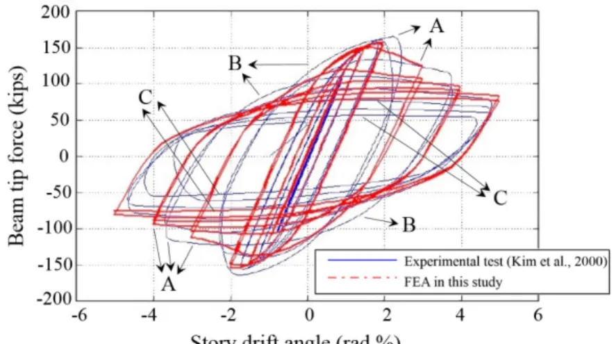
A welded flange plate specimen that was experimentally evaluated in the literature (Kim et al., 2000) is used to confirm the accuracy of finite element simulations in the present study. The results of the finite element analy-sis are compared to the experimental results of “RC06” tested by Kim et al. (2000) regarding beam tip force ver-sus story drift angle (defined in Section 3) and deformed shape as shown in Figures 2 and 3, respectively. Column and beam steel profiles, plate dimensions, column height and beam length are taken from the referred study. The tested specimen was constructed using W14x176 Grade 50 column and W30x99 Grade A36 beam.
As seen from Figure 2 the numerical and experimental results are close in linear part of the hysteretic curve. Although there are some differences between the numerical and experimental results in the non-linear region, a reasonable correlation can be seen in the whole hysteretic curve. These discrepancies may result due to the fol-lowing reasons:
1) Geometric differences between the finite element model and experimental model such as boundary conditions: In this study, the column end cross-sections are restrained against translation only in all directions. In the experimental study, the column in the tested specimen was attached to the strong floor and reaction frame using W14x311 profile. Because the deformations of the reaction frame were significant and caused the column deformations, the reaction frame displacement contributions were subtracted from the beam tip displacement in the referred study. Therefore, as seen in Figure 2 at the points “A”, differences between story drift angles of the finite element model and the experimental model may result from this adjustment.
2) Differences between material models: The material model may cause differences between hysteretic curves of the finite element model and the experimental model at the points “B” in Figure 2. In the referred study, there was no stress-strain curve of the material, just critical material points (yield and ultimate) were provided. In this study, stress-strain curve of the material is constructed from the critical material points by using the linear relationship between the points.
3) Disregarding fracture propagations in the finite element model: Due to disregarding fracture propagations, the strength of the beam section is less decrease compared with that of the experimental model. So, as seen in Figure 2 at the points “C” there are differences between beam tip forces of the finite element model and the experimental model.
Additionally, a good agreement can be seen failure modes of numerical and experimental studies as seen in Figure 3. Thus, it seems the finite element models in this study can simulate the behavior of beam-column connec-tions.
Figure 2. Comparison between hysteretic curves of the referred study (Kim et al., 2000) and this study.
3 DESIGN OF THE CONNECTIONS
In this study, the performance of WUF-W, WFP and RBS connections are assessed under cyclic loading, using European profiles. Mentioned connections are designed according to FEMA-350 using same material properties, beam span, and steel profiles, so on to make comparison possible. In the connections, compatible dimensions of the shear tab, weld access hole, flange plate and radius cut of the RBS connection are determined according to the recommended design procedures. Geometrical characteristics of the RBS connection according to FEMA-350 are given in Table 1.
Table 1: Geometrical characteristics of the RBS connection according to FEMA-350 (2000). a (0.5 to 0.75)bf
b (0.65 to 0.85)db
c ≤0.25bf
r (4c2+b2)/8c
The connections are constructed with built-up profiles corresponding to IPE270 and HE240B European pro-files which are used for beams and columns, respectively. Under lateral forces, the bending moment at the mid-span of the beam and the column is equal to zero in moment resisting frames. Therefore, in order to study the behavior of the connections, they can be considered separately from zero bending moment points. The general configuration and dimensions of the connections are shown in Figure 4 and details of the connections are shown in Figure 5. Note that for the WFP connection, the gap between the column flange and the beam is 10 mm. To sim-plify the modeling, flanges and web of profiles are considered in rectangular cross-sections and the groove welds and fillet welds are not modeled. Surface contacts are considered at the adjacencies of each of the connections. The considered contacts are coupled together both in their tangential and normal directions. This contact type is called as “Bonded” which is a linear form of contact. Therefore, no contact nonlinearities are introduced. In case of modeling the welds, non-linear contact types are considered due to friction between steel members. In relation to that, the authors observed that modeling the welds do not affect the global behavior of the connection. Therefore, modeling the welds was considered to not require.
Figure 5. Details of the connections.
Three-dimensional hexahedral solid elements (SOLID186) with three degree of freedoms per nodes are used for finite element modeling. The size of the mesh varies the length and height of the connections as can be seen in Figure 6. A fine mesh is used throughout the connection, weld access hole and flange plate to obtain more sensi-tive results.
Figure 6. Meshes of the connections: (a) WUF-W, (b) WFP and (c) RBS.
ASTM A572 Grade 50 steel is used for all components in the connections. The stress-strain relationship of the material is considered nonlinear and von-Mises yield is adopted as the yield criterion. Stress versus strain values of the material are given in Table 2. The Poisson’s ratio is taken as 0.3. The kinematic hardening rule is used for analysis of cyclic loading.
Table 2. Stress vs. strain values of ASTM A572 Grade 50 steel (Gerami et al., 2011). Stress
(MPa) Strain
361 0.00178
361 0.0196
Pan et al. (2017) showed that residual stresses resulted in the increase of PEEQ at the welds, which led to the earlier fracture of the connection. In this study, welding and fracture are not considered, thus residual stresses due to hot-rolling and weld process are disregarded in the modeling. Geometric imperfections will not affect the buckling of the beam flange since the beam has no axial force and the beam length is short due to separated from zero bending moment point. Additionally, Mathur et al. (2012) investigated residual stresses and initial imperfec-tions for seismic steel design. They found that no significant differences in the nonlinear static or dynamic re-sponses were observed between frame models that included residual stresses and initial imperfections and those without these effects. Therefore, in this study geometric imperfections are also disregarded in the modeling.
The connections are subjected to cyclic vertical displacement imposed at the loading point of the beam. Cy-clic loading history is taken from FEMA-350 and shown in Figure 7(a). Story drift angle (θ) is computed by divid-ing the total displacement at the loaddivid-ing point (ΔCL) by the distance from the loading point to the column center-line (LCL) as indicated in Figure 7 (b). Therefore, required displacement values at the loading point are computed by multiplying θ by LCL. The loading protocol is continued until the story drift angle reached the end of 7% radians. Figure 7 also shows assumptive positive and negative directions in the analyses. Moreover, geometric nonlineari-ty is considered for all connections.
Figure 7. Applying cyclic vertical displacement: (a) cyclic loading history, (b) angular rotation.
4 NUMERICAL RESULTS AND DISCUSSIONS
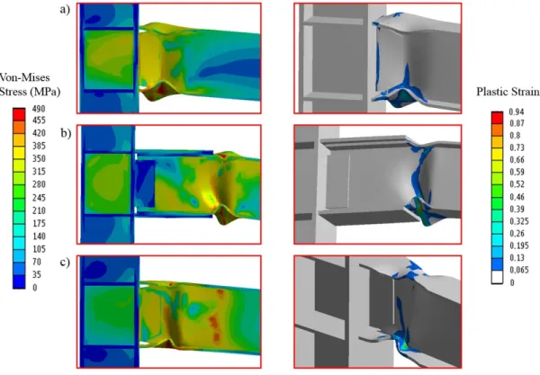
Von-Mises stress and equivalent plastic strain (PEEQ) distributions at story drift angle of 7% on the de-formed shapes of the connections are shown in Figure 8 to show the failure modes. It can be seen that failures of the WUF-W, WFP and RBS connections take place on the beam, occurrence local buckling of the beam flanges and web. Stress concentrations are observed in the buckled region of the beam and weld access hole region of WUF-W connection. Additionally, it is observed that maximum stress values of the connections are approximately same.
In the WUF-W connection, it is observed that during the 2% rad story drift angle, PEEQ values are increased slightly at the beam root (beam section which is connected to the column face). PEEQ values are greatly increased in this region until the 5% rad story drift. After that, local buckling at the beam flanges and web are observed and PEEQ distribution is concentrated in the buckled region of the beam. In the WFP connection, it is observed that PEEQ values are increased slightly at the beam root and column panel zone during the 1.5% rad story drift. PEEQ values in these regions are increased until the 4% rad story drift. After that, local buckling and PEEQ distribution at the beam flanges and web are observed at the nose of the flange plate. In the RBS connection, it is observed that PEEQ values are increased slightly at the beam root from 0.75% rad to 1% rad story drift. After that, PEEQ distri-bution is observed in the reduced region of the beam. Local buckling at the beam flanges and web in the reduced region are observed during 2% rad story drift. At the end of analyses, PEEQ distribution of WUF-W, WFP and RBS connections occur on the beam in the following locations, respectively: near the column face, end of the flange plate and middle of radius cut. Moreover, maximum and minimum PEEQ values are observed in WFP and RBS connections, respectively.
al-most constant from 1.5% drift to 7% drift, while this location of WUF-W connection changes with the story drift. It is observed that maximum PEEQ location take place near the column face at the lower story drift for the WUF-W connection. Moreover, it is observed that plastic hinge lengths of the WUF-WUF-WUF-W and RBS connections are same (approximately 230 mm), while that of WFP is less (approximately 180 mm) than those of WUF-W and RBS con-nections. As seen in Figure 9, plastic hinge locations of WUF-W, WFP and RBS connections at the end of analysis occur on the beam in the following locations, respectively: at a distance of approximately 80 mm, 370 mm and 180 mm from column flange. It is worth to say that plastic hinge takes place far the face of the column with using flange plate or radius cut.
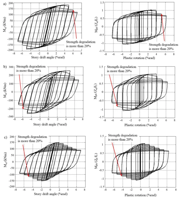
Hysteretic curves of the moment at the face of the column versus the total story drift and the normalized moment at the plastic hinge versus total plastic rotation are presented in Figure 10 for each connection. The mo-ment is computed by multiplying reaction force arising from displacemo-ment load by the distance from loading point to column face or plastic hinge. The normalized moment is being normalized to the effective plastic modulus and yield stress of the beam section at the plastic hinge. The total plastic rotation is obtained by subtracting the elastic rotations. According to the hysteretic curves, the beam moment strength is decreased after the local buckling of beam flanges and web. Hysteretic behavior of WUF-W and WFP connections do not exhibit any strength degrada-tion up to 5% story drift, while for RBS connecdegrada-tion strength degradadegrada-tion occurs after 2% story drift. AISC seismic provisions requirements (ANSI/AISC 358-10, 2000) accepts maximum 20% strength degradation up to 4% story drift angle or 3% plastic rotation. WUF-W and WFP connections exhibit more than 20% strength degradation in 6% story drift, while RBS connection exhibit mentioned degradation in 5% story drift. Therefore, each connection achieves the AISC seismic provisions requirements for special moment frames.
Figure 8. Von-Mises stress and equivalent plastic strain distributions of the connections at 7% story drift angle: (a) WUF-W, (b) WFP and (c) RBS.
As seen in Figure 10, according to the normalized moment at the plastic hinge versus plastic rotation curves, moment values at the plastic hinge are 1.014, 1.059 and 1.072 times the beam plastic moment capacity of the WUF-W, WFP and RBS connections, respectively. According to AISC seismic provisions requirements (ANSI/AISC 358-10, 2000), the probable plastic moment at the location of the plastic hinge shall be calculated by Equation 1.
d pr y ef y
M C R Z F
(1)specified minimum yield stress of that material. Zef and Fy are the effective plastic modulus of the beam at the location of the plastic hinge and the specified minimum yield stress of the material of the yielding element, re-spectively. The yield stress of the material used in this study contains Ry coefficient. Strain hardening factor esti-mated by a factor of 1.1 by the AISC seismic provision. It is observed that strain hardening factor coefficients measured from the analyses are less than that of the estimated coefficient by the AISC seismic provision. This may result from linearity of hardening part of the material model.
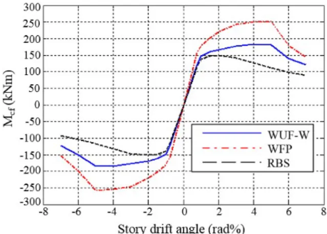
Figure 11 shows comparing the moment versus story drift angle envelopes for each connection. It is ob-served that moment capacity of WFP connection is 38% and 71% greater, respectively than those of WUF-W and RBS connections. Additionally, moment values of WUF-W and RBS connections up to 1% story drift angle are ap-proximately same. When story drift is above 1%, moment capacity of WUF-W connection is higher than that of RBS connection about 20%.
Figure 9. PEEQ index values along the beam length at different story drifts: (a) WUF-W, (b) WFP and (c) RBS. The total story drift angle, total plastic rotation and the components of the plastic rotation of the connections are given in Table 3 to investigate the overall cyclic response of the connections. The results show that maximum and minimum total and beam plastic rotation values are observed in RBS and WUF-W connections, respectively. Moreover, it is observed that panel zone plastic rotation of WFP connection is higher than those of the other con-nections, while that of RBS connection is negligible.
Table 3. Rotation values of the connections. Connection Story drift
(%) tic rotation Total plas-(%)
Beam plas-tic rotation
(%)
Panel zone plastic rotation
(%)
WUF-W 7.00 6.28 6.25 0.03
WFP 7.00 6.35 6.14 0.21
Figure 10. The moment at the face of the column versus story drifts and the moment at the plastic hinge versus plastic rotations of the connections: (a) WUF-W, (b) WFP and (c) RBS.
Figure 11. Comparison of moment versus story drift envelopes of the connections.
Figure 12. Dissipated energy versus story drift of the connections.
To further understand the connection performance, the hysteretic equivalent viscous damping ratio of the connections are examined. Hysteretic equivalent viscous damping ratio, ξhyst, is defined as;
loop hyst
max max
A
2 F D
(2)Figure 13. Equivalent viscous damping versus story drift of the connections.
PEEQ distributions of panel zones of the connections at different story drift are given in Figure 14 to look closer panel zone performance of the connections. It can be seen that maximum PEEQ quantities at the panel zone region of the WUF-W, WFP and RBS connections take place at story drift of 4%, 4% and 1.5%, respectively. After that, decreasing moment strength due to local buckling beam flanges and web causes decrease PEEQ quantities at the panel zone. Additionally, it is observed that PEEQ quantities of WFP connection are higher than those of the other connections, while that of RBS connection is insignificant. The reason of this can be explained by plastic rotation values of panel zone which given in Table 3.
Figure 15 compares initial rotational stiffness (Rin) of each connection. Here, Rin is calculated by dividing moment value by story drift angle value corresponding to yield point. It is found that maximum Rin value is ob-served in WFP connection. Additionally, Rin value of WUF-W and RBS connections respectively is 22% and 26% lower than that of the WFP connection.
Figure 16 presents the resulting Mises index which is defined as the von-Mises stress divided by the yield stress of the beam and PEEQ index values along weld access hole of WUF-W and RBS connections at 7% rad story drift. Mises index and PEEQ index values effectively decreased at the weld access hole of RBS connection. Accord-ing to considered points (A-H) of the weld access hole, Mises index value of the WUF-W connection gets maximum 33.7% (at point “E”) and minimum 1.03% (at point “A”) compared with that of the RBS connection. Moreover, it is observed that PEEQ index values at the weld access hole of the RBS connection are significantly decreased when compared with that of WUF-W connection due to the location of plastic hinge formation. Strain is concentrated at the weld access hole of WUF-W connection, especially at the point “D”, while strain concentration is negligible at that of RBS connection.
Figure 14. Equivalent plastic strain distributions of panel zones of the connections at different story drift.
Figure 16. Mises index and PEEQ index at 7% total story drift for WUF-W and RBS connections.
Table 4. Summary of performance assessment of the connections.
Parameter Sorting
Failure mode WUF-W=WFP=RBS
Plastic hinge location WFP>RBS>WUF-W Panel zone performance RBS>WUF-W>WFP Moment capacity WFP>WUF-W>RBS Energy dissipation capacity WFP>WUF-W>RBS Hysteretic viscous damping RBS>WUF-W>WFP Initial rotational stiffness WFP>WUF-W>RBS Weld access hole evaluation RBS>WUF-W
5 CONCLUSIONS
In this study, WUF-W, WFP, and RBS connection specimens were analyzed to assess the cyclic performance of the post-Northridge welded connections. ANSYS FEA software was used to do this investigation. Based on this research study, the key conclusions drawn from the numerical studies are:
Failures of the mentioned connections took place on the beam with occurrence buckling of the beam flanges and web. Plastic hinge locations of WUF-W, WFP and RBS connections occurred on the beam in the following loca-tions, respectively: at a distance of approximately 80 mm, 370 mm and 180 mm from column flange. It is worth to say that plastic hinge takes place far the face of the column with using flange plate or radius cut.
The connections managed to go beyond 4% story drift angle without more than 20% strength degradation. Therefore each connection achieves the AISC seismic provisions requirements for special moment frames.
In the investigated connections maximum and minimum moment and energy dissipation capacities, initial rotational stiffness are observed in WFP and RBS connections, respectively. It is worth to say that use of a flange plate increases moment capacity and stiffness of connection, while reducing of beam section decreases.
WFP connection is worse when compared with the other connections in terms of panel zone performance and hysteretic viscous damping ratio. It is worth to say that increasing stiffness of the connection causes to de-crease panel zone performance and hysteretic damping.
Studying the Mises index and PEEQ index in the weld access hole of WUF-W and RBS connections at the end of the cycles indicated that reduce of beam section can significantly decrease PEEQ index quantities due to the location of plastic hinge formation.
Notation
r radius of the radius cut
a distance from the radius cut to column face b length of the radius cut
c width of the radius cut
bf flange width of the beam section
db height of the beam section
PEEQ equivalent (von-Mises) plastic strain Md probable plastic moment at the plastic hinge
Cpr a factor to account for the peak connection strength
Ry the ratio of the expected yield stress to the specified minimum yield stress of the material
Zef effective plastic modulus of the beam at the plastic hinge
Fy specified minimum yield stress of the material of the yielding element
Mcf moment at the column face
Mph moment at the plastic hinge
ξhyst hysteretic equivalent viscous damping ratio
Aloop area of the closed loop of the force-displacement diagram
Fmax maximum force reached in loop
Dmax maximum displacement reached in loop
Rin initial rotational stiffness
θ story drift angle
ΔCL total displacement at the loading point
LCL distance from the loading point to the column centerline
References
ANSI/AISC 341-10 (2000). Seismic Provisions for Structural Steel Buildings, AISC, Chicago, IL.
ANSI/AISC 358-10 (2000). Prequalified Connections for Special and Intermediate Steel Moment Frames for Seis-mic Applications, AISC, Chicago, IL.
ANSYS (2015), Incorporated programmers manual for ANSYS.
Chen, C. C., Chen, S. W., Chung, M. D. and Lin, M. C., (2005). Cyclic behaviour of unreinforced and rib-reinforced moment connections. J Const. Steel Res. 61:1–21.
El-Tawil, S., Mikesell, T. and Kunnath, S. K., (2000). Effect of local details and yield ratio on behavior of FR steel connections. J. Struct. Eng. ASCE 126: 79-87.
FEMA (2000). Recommended seismic design criteria for new steel moment-frame buildings: FEMA-350, Rich-mond (CA): SAC Joint Venture.
Gerami, M., Saberi, H., Saberi, V. and Daryan, A.S., (2011). Cyclic behavior of bolted connections with different arrangement of bolts. J Const. Steel Res 67: 690–705.
Gholami, M., Deylami, A. and Tehranizadeh, M., (2013). Seismic performance of flange plate connections between steel beams and box columns. J Const. Steel Res. 84: 36-48.
Han, S. W., Kwon, G. U. and Moon, K. H., (2007). Cyclic behaviour of post-Northridge WUF-B connections. J Const. Steel Res. 63: 365–374.
Han, S. W., Moon, K. H. and Jung, J., (2014). Cyclic performance of welded unreinforced flange-welded web mo-ment connections. Earthquake Spectra, 30: 1663-1681.
Kim, T., Whittaker, A. S., Gilani, A. S., J., Bertero, V. V. and Takhirov, S. M., (2000). Cover-plate and flange-plate rein-forced steel moment-resisting connections. PEER Report 2000/07, Pacific Earthquake Engineering Research Cen-ter, University of California, Berkeley.
Kim, T., Whittaker, A. S., Gilani, A. S., J., Bertero, V. V. and Takhirov, S. M., (2002a). Experimental evaluation of plate-reinforced steel moment-resisting connections. J. Struct. Eng. ASCE 128: 483-491.
Kim, T., Whittaker, A. S., Gilani, A. S., J., Bertero, V. V. and Takhirov, S. M., (2002b). Cover-plate and flange-plate steel moment-resisting connections. J. Struct. Eng. ASCE 128: 474-482.
Kim, T., Stojadinović, B. and Whittaker, A. S., (2004). Seismic performance of US steel box column connections, 13th World Conference on Earthquake Engineering. Vancouver, B.C., Canada, Paper No. 981.
Kim, T., Stojadinović, B. and Whittaker, A. S., (2008). Seismic performance of pre-northridge welded steel moment connections to built-up box columns. J. Struct. Eng. ASCE 134: 289-299.
Kim, T., Kim, U. S. and Kim, J., (2012). Collapse resistance of unreinforced steel moment connections. Struct Design Tall Spec Build 21: 724-735.
Kosarieh, A. H., Danesh, F. and Shiri, R., (2015). Column axial load effects on performance of panel zone in welded-flange-plate connections. Adv in Struct Eng 18: 775-789.
Lu, L. W., Ricles, J. M., Mao, C. and Fisher, J. W., (2000). Critical issues in achieving ductile behaviour of welded moment connections. J Const. Steel Res. 55: 325–341.
Mao, C., Ricles, J., Lu, L. W. and Fisher, J., (2001). Effect of local details on ductility of welded moment connections. J. Struct. Eng. ASCE 127: 1036-1044.
Mathur, K., Fahnestock, L. A., Okazaki, T. and Parkolap, M. J., (2012). Impact of residual stresses and initial imper-fections on the seismic response of steel moment frames. J. Struct. Eng. ASCE 138: 942-951.
Nia, Z. S., Ghassemieh, M. and Mazroi, A., (2013). WUF-W connection performance to box column subjected to uniaxial and biaxial loading. J Const. Steel Res. 88: 90-108.
Nia, Z. S., Mazroi, A., Ghassemieh, M. and Pezeshki, H., (2014). Seismic performance and comparison of three dif-ferent I beam to box column joints. Earthq Eng & Eng Vib 13: 717-729.
Pachoumis, D. T., Galoussis, E. G., Kalfas, C. N. and Efthimiou, I. Z., (2010). Cyclic performance of steel moment-resisting connections with reduced beam sections - experimental analysis and finite element model simulation. Eng Struct. 32: 2683-2692.
Pan, J., Chen, S., Lai, Z., Wang, Z., Wang, J. and Xie, H., (2017). Analysis and fracture behavior of welded box beam-to-column connections considering residual stresses. Construction and Building Materials 154: 557-566.
Ricles, J. M., Fisher, J. W., Lu, L. W. and Kaufmann, E. J., (2002). Development of improved welded moment connec-tions for earthquake-resistant design. J Const. Steel Res. 58: 565–604.
Roeder, C. W., (2002). Connection performance for seismic design of steel moment frames. J. Struct. Eng. ASCE 128: 517-525.
Saffari, H., Hedayat, A. A. and Goharrizi, N. S., (2013). Suggesting double-web I-shaped columns for omitting conti-nuity plates in a box-shaped column. Steel and Composite Struct 15: 585-603.
Stojadinovic, B., Goel, S. C., Lee, K. H., Margarian, A. G. and Choi, J. H., (2000). Parametric tests on unreinforced steel moment connections. J. Struct. Eng. ASCE 126: 40-49.