Project
Master in Product Design Engineering
Design evaluation on the production of sloping walls without support structures in additive manufacturing
Inês Carolina Ribeiro Lemos
Project
Master in Product Design Engineering
Design evaluation on the production of sloping walls without support structures in additive manufacturing
Inês Carolina Ribeiro Lemos
Project Report developed under the supervision of Professor Henrique de Amorim Almeida and co-supervision of Professor Mário António Simões Correia, professors at the School of Technology and Management of the Polytechnic Institute of Leiria.
iii
Acknowledgements
I wish to express my deepest gratitude to my advisers, Professor Henrique Almeida and Professor Mário Correia for all the help, encouragement and guidance during my research at the School of Technology and Management of the Polytechnic of Leiria (ESTG - IPL). I also would like to thank them for sharing their expertise and offering their knowledge.
This work would not be possible without the equipment provided by the Polytechnic Institute of Leiria and the Electrical Engineering Department. I would like to extend my gratitude to Professor Carlos Neves for all the help and support.
I also would like to thank to the company S3D for the opportunity of interact with the equipment that contributed for my research.
To the company Cadmold for always showing availability to let me perform part of my work. Thank you for the friendship that I truly carry.
To my family for the understanding, confidance and for always support my endeavors.
And finally to my amazing boyfriend, Rodolfo for always believing in me, for all the support, encouragement and for the everyday inspiration.
Muito Obrigada, Mãe, Pai, Irmão, Rodolfo
v
Resumo
As tecnologias em geral têm avançado significativamente ao longo dos anos. A fabricação aditiva é uma das tecnologias que está em constante crescimento numa questão de aplicações, materiais, processos e máquinas. Existem alguns constrangimentos em consequência do crescimento acelerado, sendo que em alguns casos os modelos precisam de construir estruturas de suporte o que torna o processo de produção mais lento. É necessário entender este tipo de limitações. A fabricação aditiva tem a capacidade de produzir partes geométricas através de um modelo CAD criando protótipos rapidamente por união de materiais, camada a camada, para representar modelos ou até para testar a sua funcionalidade. É uma tecnologia capaz de imprimir peças geométricas e complexas com uma extensa liberdade, mas com a necessidade de produzir estruturas para suportar a peça. A tecnologia de FDM é um processo de fabricação aditiva que produz o modelo com a conexão de materiais poliméricos camada a camada. O programa da máquina lê e manipula os ficheiros STL de maneira a definir a as melhores condições para a impressão do modelo pretendido, também define a necessidade de produzir estruturas de suporte. É relevante estabelecer diretrizes de design para alcançar um melhor resultado. Assim sendo, o foco desta tese é avaliar a necessidade da existência de estruturas de suporte num conjunto de modelos definidos com uma geometria específica. O trabalho consistiu por produzir modelos com paredes inclinadas através do processo de FDM em diferentes máquinas para perceber os diferentes comportamentos das formas e concluir até que ponto é possível produzir a peça sem estruturas de suporte dentro dos parâmetros definidos.
Palavras-chave: Fabricação aditiva, FDM, material de suporte, paredes inclinadas.
vii
Abstract
Technologies have been advancing significantly over the years. Additive manufacturing is a technology that is in constant growth in the matter of applications, materials, processes and machines. In spite of its advanced technology, in most cases the produced models need to build with support structures which slows down production. Hence it is necessary to understand this type of limitation. Additive manufacturing has the ability of producing geometrical parts from a CAD model, creating rapidly physical models by joining materials, layer by layer, to represent models or even to test its functionality. It is capable of printing geometrical complex parts with an extended design freedom, but in some systems, needs to build support structures to support the part during production. The FDM technology is one of the additive manufacturing processes that produces the model by connecting polymeric materials one layer at a time. The machine software reads and manipulates the STL file to define all the proper conditions to print the required model, as well as defining the need to build support structures. It is relevant to establish design guidelines to achieve an improved result. Therefore, the focus of this thesis is to evaluate the need of support structures in a set of defined models with designated geometric characteristics. The work consisted in producing models with sloping walls using the FDM process in different machines in order to understand the different behaviours of the shapes and to conclude at which point it is possible to produce a geometric feature without support structures while maintaining geometric accuracy.
ix
List of Figures
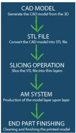
Figure 1 - General steps of Additive manufacturing. ... 4
Figure 2 - Manufacturing processes. ... 5
Figure 3 - SLA process scheme. ... 6
Figure 4 - MPSL process scheme. ... 7
Figure 5 - SLS process scheme. ... 10
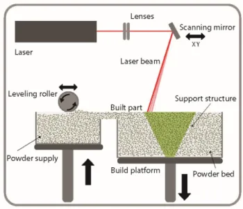
Figure 6 - SLM process scheme. ... 13
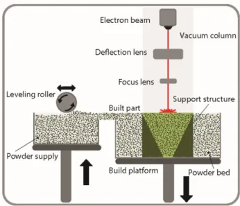
Figure 7 - EBM process scheme. ... 14
Figure 8 - Binder jetting process scheme. ... 17
Figure 9 - Material jetting printing process scheme... 19
Figure 10 - LOM process scheme. ... 22
Figure 11 - FDM process scheme. ... 24
Figure 12 - CAD models for each considered printing angle α: a) 10º, b) 30º, c) 50º, d) 70º, e) 90º.. ... 31
Figure 13 - Mojo Printer from Stratasys (2008)... 32
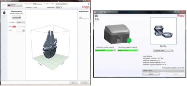
Figure 14 - Left Print Wizard software and Right Mojo Panel Control... 32
Figure 15 - Hello Bee Prusa (2015). ... 33
Figure 16 - On the left the Slic3r software while on the right the Pronterface software. ... 34
Figure 17 - ATOS Core 135. ... 34
Figure 18 - GOM Scanning Software for the ATOS Hardware... 35
Figure 19 - Geomagic Qualify 2012 software. ... 36
Figure 20 - Models Printed by Mojo: a) α=10º, b) α=30º, c) α=50º, d) α=70º, e) α=90º. ... 40
Figure 21 - Printed model with α=43º by Mojo. ... 41
Figure 22 - Models Printed by Prusa: a) α=10º, b) α=30º, c) α=50º, d) α=70º, e) α=90º. ... 42
Figure 23 - Model with α=43º printed in Prusa. ... 43
Figure 24 - Model α=19º for a) Prusa b) Mojo. ... 44
Figure 25 - Damaged model with α=19º printed in Prusa. ... 45
Figure 26 - Printing process of model B. ... 45
x
Figure 28 - Model A printed in Prusa. ... 47 Figure 29 - Scanning process of the models. ... 48 Figure 30 - Coating process. ... 49 Figure 31 - Scanning performance assessment considering α=43º and the Mojo printer: a) without powder, b) with powder. ... 49
Figure 32 - Overlapping of the CAD file with its respective STL file for model D printed in the Mojo printer. ... 50
Figure 33 - Cutting section from the overlapping of the CAD file with its respective STL file for α=43º and height=5mm, printed in Mojo printer. ... 51
Figure 34 - Illustration of the printing flaws for model C from the Prusa printer at height=5mm. ... 51
Figure 35 - Overlapping of the scanned model with CAD file in Geomagic software. ... 55 Figure 36 - Average excess material error value versus α and height, for models printed in: a) Mojo b) Prusa printers. ... 57
Figure 37 - Average lack of material error value versus α and height, for models printed in: a) Mojo b) Prusa printers. ... 58
Figure 38 - Standard deviation value versus α and height, for models printed in: a) Mojo b) Prusa printers. ... 59
Figure 39 - Seam example of an α=70º model: a) 3D model using Mojo b) cutting section of Mojo model c) 3D model using Prusa d) cutting section of Prusa model. .... 60
xi
List of Tables
Table 1 - Designing for SLA printing (Courtney Armstrong, n.d.). ... 8
Table 2 - Designing for SLS printing (Oceanz, n.d.). ... 12
Table 3 - Designing for metal processes (Redwood, n.d.). ... 15
Table 4 - Designing for binder jetting processes (Varotsis, n.d.). ... 18
Table 5 - Designing for material jetting processes (Varotsis, n.d.)... 21
Table 6 - Designing for material extrusion (Redwood, Schöffer, and Garret 2017). ... 25
Table 7 - Advantages, Disadvantages and Geometric aspects of AM processes. . 27
Table 8 - Material, Support material and Applications of AM processes. ... 28
Table 9 - Assigned letter for each printing angle. ... 38
Table 10 - Time and number of layers for each model, considering both printers. ... 38
Table 11 - Support material evaluation for different angles. ... 41
Table 12 - Support material evaluation for different angles. ... 43
Table 13 - Applicable models for scanning process. ... 47
Table 14 - Geomagic data from models printed in MOJO... 52
xiii
List of
Acronyms
AM – Additive Manufacturing 3D – Three Dimensional
CAD – Computer Aided Design STL – Stereolithography File SLA – Stereolithography UV – Ultraviolet
MPSL – Mask Projection Stereolithography SLS – Selective Laser Sintering
DMLS – Direct Metal Laser Sintering SHS – Selective Heat Sintering SLM – Selective Laser Melting EBM – Electron Beam Machining 3DP – Three-Dimensional Printing MJM – Multi-Jet Modelling
LOM – Laminated Object Manufacturing FDM – Fused Deposition Modelling ABS – Acrylonitrile Butadiene Styrene PLA – Polylactic Acid
xv
Table of Contents
ACKNOWLEDGEMENTS III RESUMO V ABSTRACT VII LIST OF FIGURES IX LIST OF TABLES XILIST OF ACRONYMS XIII
TABLE OF CONTENTS XV
1. INTRODUCTION 1
2. ADDITIVE MANUFACTURING 3
2.1. Vat Photopolymerization 6
2.1.1. Direct Writing - Stereolithography 6
2.1.2. Mask Projection Stereolithography 7
2.1.3. Geometric aspects 8
2.2. Powder Bed Fusion 10
2.2.1. Sintering Processes 10
2.2.2. Melting Processes 13
2.3. 3D Printing 16
2.3.1. Binder Jetting – Indirect Inkjet Printing 17
2.3.2. Material Jetting 19
xvi
2.4.1. Geometric aspects 23
2.5. Material Extrusion – Fused Deposition Modelling 23
2.5.1. Geometric aspects 24
2.6. Process Overview 26
3. EXPERIMENTAL FRAMEWORK 29
3.1. Selected designs for the experimental framework 29
3.2. FDM Equipment and Materials 31
3.3. 3D Scanning System for Geometric Evaluation 34
4. RESULTS AND DISCUSSIONS 37
4.1. Production of the physical models 39
4.1.1. Production with the Mojo Printer 39
4.1.2. Hello Bee Prusa printer 42
4.1.3. Support material removal 45
4.2. Digital Scanning of the Physical Models 47
4.3. Geometric Evaluation of the physical models 49
5. CONCLUSION 63
6. FURTHER WORK 65
1
1.
Introduction
In the last decades, the knowledge about Additive Manufacturing (AM) technologies has improved and has enabled to produce new and geometrically complexed parts with single or multiple materials. Several studies are focused on improving additive manufacturing technologies and comparing different processes with each other or to conventional processes (Vayre, Vignat, and Villeneuve 2012).
Since it is a subject that has been growing, it is necessary to analyse the limitations and constraints about additive manufacturing technologies. From a design perspective, the challenge of additive manufacturing is to understand the limitations and opportunities of the new processes and on how to use them in the right applications (Klahn, Leutenecker, and Meboldt 2015).
However, to create complex geometries, sometimes it is essential to have support structures, not only for supporting the piece being built but also to ensure accuracy while the part is being built. The support structure is an additional printed structure, needed to support the model onto the platform during the building process. Without support structures, parts of the model that have not yet achieved their full strength may collapse during the process (Ezair, Massarwi, and Elber 2015). Specifically, the manufacturing material cannot be deposited on a layer where there is insufficient material on the previous layer (Hu, Jin, and Wang 2015). The disadvantage of support structures is that it slows down the process during and after the building stage, namely their removal, increasing production times, energy and material wastage.
It is important to study the impact of support structures. From a designer poin of view, it is imperative to have this knowledge. This work seeks to identify and to study the limitation of the support structures used in Fused Deposition Modelling (FDM) systems in order to create a design guideline.
2
1.1. Global Objectives
This work pursues to add knowledge on support structures studies regarding geometrical limitations in models produced by FDM processes. In some situations, it is not possible to eliminate completely the support structure needed to print the desirable model which could create a limitation in the final part. In other cases, it is possible to ignore the production of support structures during printing.
The purpose of this work is to evaluate and compare the geometric behaviour of a set of models with defined geometric characteristics, such as wall angles. In this research work, the parts were printed in two different FDM machines and in the same material, namely ABS.
1.2. Thesis structure
Besides the Introduction, Conclusion and suggestions for Further Work, this project report has in addition of 3 chapters:
The second chapter describes the state of the art of additive manufacturing technologies. Introduces and categorizes the existing additive manufacturing technologies explaining their advantages, disadvantages, applications and geometrical concerns of each technology that are relevant for this research.
The third chapter refers to the experimental set-up describing the selected design, materials of choice, methods and all the equipments used for the case study. It also refers to the selection and creation of the designs for the experiments based on the research on the geometrical concerns described in the previous chapter.
The discussion of the experimental results is explained in chapter 4. The Stratasys – Mojo and Hello Bee Prusa were used to print the parts. The parts were then scanned by a 135 ATOS Core system in order to evaluate their geometric deviation between the printed parts and the 3D CAD models.
3
2.
Additive Manufacturing
In the late 1980s, it is when the first additive manufacturing technology became visible and presented commercially (Guo and Leu 2013). However, additive manufacturing technology goes back earlier into previous decades. From the 1960s to the 1970s, additive manufacturing for many were only registered patents not worthy to be recognized. Until the late 1980s and early 1990s, AM technologies experienced an accentuated growth in patents and research publications. Since that time, the number of new technologies and the integration of different materials in diverse processes increased significantly and its advances continuous to growing every day. With its evolution and diversification, soon there will be a time where these technologies will be called as common technologies in any production line.
Additive manufacturing or 3D printing (3DP) is a technology defined as a process capable of producing 3D models by uniting materials, layer by layer without requiring the use of individual tools. AM technologies have been qualified to produce parts of polymers, metals, ceramics and composites. AM technologies also requires a 3D modelling software (Computer Aided Design or CAD) and other conventional manufacturing technologies such as machining equipments. First, a digital model is developed, then the CAD model must be converted into a file that the 3D printer software can read, usually a STL file. The STL file consists of the model in triangular facets approximating the shape of the object. The 3D printer software reads the STL, processes the data and defines support structures if required. The next step consists of the production of the physical model. Finally, the model is removed from the building platform and all the support material is eliminated when required. The support material is removed depending on the process and material. The model is cleaned and treated (Figure 1). The support generation in some processes of AM is usually required. The support structures can be manually removed, water-soluble or during post-processing which can cause marks/sinks damaging the desired part. The main function of support structure is to anchor the model to the building platform, also to provide a structural stability during production to avoid geometric innacury. There are several aspects to considered to minimize the amount of material used to support the part, and it can be calculated through the software but it depends on the shape, orientation and size of the part.
4
Figure 1 - General steps of Additive manufacturing.
However, it is relevant to analyse AM’s advantages pros and cons limitations in general. AM has advantages as it can build small batches of customized low-volume parts that cannot be economically produced by other traditional methods. Also, can build intricate and complex geometries without the need of assembly, therefore, producing almost any shape. Integrates different fields and industries, for example, design, fashion, medicine, automobile, among others. Can detect early flaws and errors that can be amended before the mass fabrication stage. Since it doesn’t need tooling and moulds, because it is a direct production there are no additional costs, beside the building machine equipment. On the other hand, in some processes the cost of machinery and materials is high. The orientation of the part during production influences its mechanical performance, making the part less resistant in other directions. The orientation of the part also influences the geometric quality some geometric features due to the stair case effect. Usually, the built surface is rougher than the machined surface. In some cases, the support structure materials can't be recycled being necessary to minimize them during production and also to reduce the production time. In some materials the mechanical and thermal properties are not suitable, because they can be brittle.
5
A designer is able to create a truly additive design when he understands the characteristics of additive manufacturing (Klahn, Leutenecker, and Meboldt 2015).The awareness about AM challenges is important to minimize the impact on production and to create an optimised part. Selecting the optimal 3D printing process for a particular design can be difficult (Redwood, Schöffer, and Garret 2017). The choice of material and process is relevant to achieve a good result, being important to analyse different printers and processes.
The range of 3D printing methods and materials means that often several processes are suitable, with each one offering variations in properties like dimensional accuracy, surface finish and post processing requirements (Redwood, Schöffer, and Garret 2017). There are several geometric aspects to consider for AM processes when designing a part: the orientation, geometric tolerance, material, support structure, among others such as geometric aspects that are going to be referred according to each process.
It is possible to classify AM Technologies into different categories: powder, liquid and solid-based systems according to different materials. It is easy to find several ways to classify these systems. One possible classification is presented in Figure 2 and it is obvious the variety of existing processes.
6
2.1. Vat Photopolymerization
2.1.1. Direct Writing - Stereolithography
Stereolithography (SLA) processes produces 3D models by turning a liquid photopolymer resin into the solid state, solidifying it, with the aid of an ultraviolet (UV) laser beam. A tank is filled with a liquid resin where the building platform is submerged. The system starts mapping each layer in the building platform by solidifying the material. After this step, platform lowers letting a new layer of resin to stream over. This process is duplicated layer upon layer until the part is fully printed. Illustrated in Figure 3. After production, the post-processing is performed, namely the removal of the excess resin and support structures and then cleaned with a solution to eliminate existing residues. Afterwards, it goes through a curing process to fully solidify. SLA requires support structures otherwise the part may collapse during production. In the vat photopolymerization process, the support structures are built in the same material as the model part, but in a thinner thicknesses so that it can be removed manually without damaging the part when done carefully (Almeida and Correia 2016).
––
Figure 3 - SLA process scheme.
SLA is a process that may be used for jewellery (investment casting), dental and medical applications (hearing aids). As advantages, the building speed is high, and it is capable of producing small and intricate models with smooth surface finish and accurate detail. On the other hand, adding to the limited range of materials, the materials are also
7
expensive. The SLA process is limited to photopolymers. As mentioned before, SLA requires support structures and consequently during their removal, if not carefully removed, the part may end up with superficial defects. Advisedly, the support structures should be created at the least visible surfaces.
2.1.2. Mask Projection Stereolithography
Similar to SLA, the Mask Projection Stereolithography (MPSL) produces the physical models by solidifying photosensitive resins. In this case, each layer is produced in one single instant. Each layer section results from a sliced cross section stored as bitmaps to be displayed on the dynamic LCD mask. UV radiation reflects off of the “on” micro-mirrors and is imaged onto the resin surface to cure a single layer. The building platform slides upward providing a thin layer of new resin between the previous layer and the bottom of the resin tank, building the part upside down. In some systems, such as the VFlash system, the part is not produced in a liquid resin tank but produced with the aid of a cartridge that provides a resin film for each layer. In either system, this process continues until the entire part is built (Gibson, Rosen, and Stucker 2010). Figure 4 illustrates the MPSL process. Support structures are often necessary which have to be removed during the post-processing of the part.
8
MPSL is essential for electrical and automotive parts. This technology, comparing to the SLA process is faster but it is also limited to the same material constraints, photopolymers and cost.
2.1.3. Geometric aspects
For both SLA and MPSL the support structures have a big effect on the surface finish. Since the support material is the same as the build material but thinner to facilitate their removal, and since it is performed manually, the removal of the support structures may leave marks on the surface of the part if not done properly. This issue is strongly influenced by the orientation of the part during production. If the part is strategically oriented, it ensures that the important surfaces are not in touch with the support structures in order to obtain a smooth surface. Complex details in inaccessible areas will make removal of support structures difficult and increases the likely hood of damaging the part (Redwood, Schöffer, and Garret 2017). The support structures secure the part from collapsing during production, therefore it is difficult to produce hollow parts because it is not possible to remove the support structures within the interior of the part. It is important to make sure that the interior doesn’t need support structures. For MPSL, since it prints micro parts, support structures become more difficult to remove.
The level of detail that a SLA printer can produce is dependent on the laser spot size and resin properties. General guidelines for designing for SLA are as follows:
Table 1 - Designing for SLA printing (Courtney Armstrong n.d.).
Feature Description
Supported walls: Walls that are connected to other structures on at least two sides have very little chance of warping. These should be designed at a minimum of 0.4 mm thick.
9
Unsupported walls: Walls that are connected on less than two sides present a high chance for warping or detaching from the print. These walls must be at least 0.6 mm thick and should be designed with filleted bases reducing stress concentrations along the joint.
Overhangs: Overhangs pose little threat unless the model is being printed without adequate internal and external support structures. Printing without supports often leads to warping of the print, but if printing without supports is necessary, any unsupported overhangs must be kept less than 1.0 mm in length at 90º and for slopping walls a minimum of 19° from level.
Embossed details (including text): Any features on the model that are raised slightly above the surfaces around them must be at least 0.1 mm in height above the surface of the print to ensure visibility of the printed details.
Engraved details (including text): Any features which are imprinted or recessed into the model are at risk of fusing with the rest of the model while printing if they are too small, therefore these details must be at least 0.4 mm wide and 0.4 mm in depth.
Horizontal bridges: Bridges between two points on a model can be successfully printed, but the designer must keep in mind that wider bridges must be shorter (less than 21 mm) than thinner bridges. Wider bridges have a higher z-axis area of contact increasing the chance of print failure during peeling.
Holes: Holes with a diameter less than 0.5 mm may close off during printing.
Connections:
• 0.5 mm clearance between moving parts. • 0.2 mm clearance for assembly connections. • 0.1 mm clearance will give a push or snug fit.
10
2.2. Powder Bed Fusion
2.2.1. Sintering Processes
a) Selective Laser Sintering
Selective Laser Sintering (SLS) is a sintering process that begins by heating the material to a temperature below the melting point bonding together the powder that is been sintered. The layers of powder material are deposited onto a building platform in order to produce the physical model. The laser selectively sinters the powder and solidifies a cross section of the part (Redwood, Schöffer, and Garret 2017). After each cross section is scanned, the power bed is lowered by one layer thickness, a new layer of material is spread on top, and the process is repeated until the part building is completed (Guo and Leu 2013) as illustrated in Figure 5.
Figure 5 - SLS process scheme.
SLS is used for producing functional prototypes and parts. The major advantage of laser sintering is the almost complete design freedom. Unlike other AM processes such as SLA and FDM, SLS does not require support structures. The excess un-sintered powder acts as a support for the part that is been produced, allowing for complex and intricate shapes to be manufactured with no additional support needed. In summary, SLS does not require support structures because the part been built is surrounded by un-sintered powder (Guo and Leu 2013). SLS produces in a wide range of materials with
11
good mechanical properties and complex geometries. However, the finished objects require more time to cool down hence the production time increases.
b) Direct Metal Laser Sintering
Direct Metal Laser Sintering (DMSL) is a technology similar to SLS but instead produces metallic alloy parts by using a laser to sinter the metallic alloy powder near its melting point allowing the sintered powder to fuse. In this case, the gap between the processing temperature and melting temperature is less than in SLS systems due to the use of metallic powders. Unlike SLS, DMLS needs support structures to avoid distortions of the part. Due to the high temperatures involved in the process and the layer by layer nature of part construction, support structures are required to connect unsupported geometries to the building platform and act as a heat sink for excess thermal energy and also to support the weight of the metallic part been built (Redwood, Schöffer, and Garret 2017). The support structures are then removed in post processing stage.
DMLS produces functional parts and tools for several demanding industries such as aerospace, automotive, medical, dental and jewelry. This process has the ability to produce fully dense parts with a high design freedom and complexity. It is possible to produce complex parts because there is no tooling, only in the post-processing support structures are removed the support structures. Additionally, the build parts have high specific strength and stiffness. Adversely, the surface finish quality depends on the grain size of the powder, and also the cost is high and the building size has limitations.
c) Geometric aspect
SLS parts often suffer big distortion and warping. The orientation of the part is very important to avoid distortion of builded part. One geometric aspect to be considered when designing parts, is the volume of the part that should be reduced in order to avoid distortion. For the DMLS process, the support structures are really difficult to remove when compared to printed polymer parts. Generally, when more support structures are included in the design, more accurately the part will be, but higher cost, post processing time and difficulty in removing them (Redwood, Schöffer, and Garret 2017).
12
The detail level that a SLS printer can produce depend on the processing parameters of the laser and the material properties. General guidelines for designing for SLS are as follows. Regarding the DMLS process, since it is metal based, the general guidelines will be presented with the melting processes.
Table 2 - Designing for SLS printing (Oceanz n.d.).
Feature Description
Wall thickness: The minimum wall thickness to ensure a successful print varies between 0.7 mm (for PA12) up to 2.0 mm (for carbon filled polyamide).
Hole size: All holes should be larger than 1.5 mm in diameter.
Escape holes: To save weight (and sometimes costs) SLS parts are printed hollow. But in order to remove unsintered powder after production escape holes must be included. Escape holes must have a minimum of 3.5 mm in diameter.
Feature size (pins, protruding features etc.): A minimum size of 0.8 mm is recommended.
Embossed and engraved details: To ensure the visibility of the printed details, the following values are required:
• Minimum depth of engraving 1 mm • Minimum height of embossing 1 mm
Tolerances: Typical tolerances for SLS parts are within ± 0.3 mm or ± 0.05 mm/mm.
13
2.2.2. Melting Processes
a) Selective Laser Melting
Selective Laser Melting (SLM) process is based on SLS process, but in this case uses a high-power laser beam to melt successive metallic powder layers. The laser will heat particles on a metallic power bed until completely melted. The powder is delivered and spread over the plate by the levelling roller, similar to the previous powder processes. Laser scanning begins with predefined tracks after the powder has been spread over the plate. After the layer scanning concluded, building platform is lowered in the depth of a layer and new powder is spread over the previous layer (Zeng 2015). The building process is done in a chamber with an inert gas environment in order to avoid metal oxidation (Gao et al. 2015). The SLM scheme is illustrated in Figure 6. This process is repeated until full part is printed. SLM requires support structures during production for similar reasons such as the DMLS process, as the powder acts as a natural support in the building process. After production, parts may require surface finishing procedures such as milling in order to remove the support structures.
Figure 6 - SLM process scheme.
SLM is capable to produce functional metallic parts and tools. Typically, the systems requires large amount of energy which can be more difficult to control. This technology is also able of producing complex geometries. As DMLS, SLM have low structural properties, size limitations and the surface finish depends on the size and quality
14
of the powder grain. The difference between SLM and DMLS systems is that SLM achieves a full melt while DMLS only sinters the powders. This means that DMLS only works with alloys (nickel alloy, Ti6AlV4 alloy, etc.), whereas SLM does not operate with combination of different metals. For example, the building material could be either aluminium, or titanium, or copper, or stainless steel.
b) Electron Beam Melting
In Electron Beam Melting (EBM) the machine delivers a layer of melted metal powder in a layer by layer fashion on the building platform, which is melted by the electron beam and then fused. The actual building process is done in a vacuum environment in order to avoid metal oxidation (Gao et al. 2015). Similarly to SLM and DMLS, EBM parts require support structures to support the building part and allow excess heat to transfer away from the melted powder. After part production, it is required a post-processing to remove support structures and the excess powder is removed and reused. Figure 7 represents a simple scheme of EBM process.
Figure 7 - EBM process scheme.
The fabricated parts are fully dense, free of voids, and extremely strong (Guo and Leu 2013). Since the building process occurs in a vacuum environment, despite the costs, this eliminates impurities. Besides these processing characteristics, it is able to process titanium which makes this technology the most adequate for the production of medical implants. Other sectors such as aerospace and automotive industries also turn to this
15
technology when titanium parts are required. It is able to print multiple components at the same time.
c) Geometric aspects
SLM parts suffers a residual stress or risk of failure or cracking can be caused by thermal gradients, but with the combinations of high temperature and suitable cooling the parts are more strong and durable. The rule is to avoid sloping walls, because for the case of lower building angles more support structure are needed.
The detail level that a DMLS, SLM and EBM printer can produce is dependent on the processing parameters of the laser or electron beam and the metallic properties. General guidelines for designing for melting processes are as follows:
Table 3 - Designing for metal processes (Redwood n.d.).
Feature Description
Wall thickness: The minimum thickness to ensure a successful print is commonly 0.4 mm, dependending on material, orientation and printer parameters.
Pin diameter: The minimum reliable pin diameter is 1 mm.
Hole size: Hole diameters between 0.5 mm and 6 mm can be printed reliably without supports. Support free building of hole diameters between 6 mm and 10 mm is orientation dependent. Above 10 mm, support structures are required.
16
Escape holes: Holes are required on hollowed metal parts to remove unmelted powder. A bore hole diameter of 2-5 mm is recommended. Using multiple escape holes will greatly improve the ease of powder removal.
Overhanging Surfaces: The minimum angle where support material is not required on an overhanging surface is 45º relative to the horizontal. It is possible to reduce this angle further by optimizing the laser parameters.
Feature size (pins, protruding features etc.): A minimum size of 0.8 mm is recommended.
Unsupported Edges: The maximum length of a cantilever-style overhanging surface is 0.5 mm. An overhanging horizontal surface supported on both ends can be 1 mm long. These rules will apply to embossed and engraved features with unsupported surfaces as well.
Aspect Ratio: The maximum ratio between the vertical print height and the part section is 8:1 to ensure stability of the printed part on the build plate.
Tolerances: Part tolerance in the print direction is ± 1 layer thickness. In the XY plane, the achievable tolerance is ± 0.127 mm.
2.3. 3D Printing
3D printing includes the following techniques: binder jetting, that refers to indirect inkjet printing and material jetting, that describes inkjet printing and multi-jet modelling.
17
2.3.1. Binder Jetting – Indirect Inkjet Printing
Binder printing process creates parts with a binding agent. The liquid agent is deposited onto a bed of powder through a nozzle uniting the part, in a layer by layer fashion until the part is complete. When finished, the part is in a green state, then is removed from the building platform and cleaned and all the excess powder removed. Then needs to be infiltrated so that the part becomes more resistant and ready for use. This process does not require additional support structures since the excess of un-binded powder acts as support structure. Figure 8 ilustrates the binder jetting process.
Figure 8 - Binder jetting process scheme.
Architectural models and sculptures are the main application for indirect inkjet printing due to the ability to print in full colours and to produce highly complexed geometries. It is a process that requires less energy, since no laser or electron beam is envolved, but when compared to SLS nonetheless, the parts are not as strong and the surface finish tends to be grainy.
a) Geometric aspects
As mentioned before, parts after being printed are in a fragile green state, which adds restrictions to the designs that can be printed such as thin features that may break in the green state during handling. The part needs to be reinforced with extra structures
18
because when pressurized air is applied to remove the excess powder, the part can be damaged or even break. General guidelines for designing for binder jetting are as follows:
Table 4 - Designing for binder jetting processes (Varotsis n.d.).
Feature Description
Wall thickness: The recommended minimum value for parts is 2.0 mm. This ensures that the part can be removed from the powder and handled in the green state without being damaged.
Unsupported walls (including fins or ribs): These features are at a greater risk of being damaged during handling and should not be thinner than 3.0 mm.
Embossed and engraved details: To ensure the visibility of the details, embossed and engraved details should be at least 0.5 mm below or above the surface.
Unsupported edges: Although the powder surrounding the part offers support during building, unsupported edges are at a high risk of breaking during handling in the green state. Unsupported edges should be no longer than 20 mm.
Fillets: All fillets should be a minimum of 1.0 mm in radius and used in all edges of the design where possible. This ensures that they the part will not be damaged in the green state.
Hole size: For a hole to be successfully printed the minimum diameter should be no smaller than 1.5 mm.
Escape holes: Binder Jetting is able to produce parts with hollow sections, but in order to remove the unbound powder after printing, escape holes must be included in the design. The holes must have a minimum of 5.0 mm in diameter and the use of at least 2 escape holes is recommended.
19
Feature size: The main concern with minimum feature size is the potential for damage. Although the process is able of producing parts with very fine details, the main concern regards the handling of the part in the green state. Because of this, a minimum feature size of 2.0 mm is recommended.
2.3.2. Material Jetting
a) Inkjet Printing
Similar to binder jet printing technology that transfers ink droplets from a fluid channel onto the powder substrate in a drop by drop fashion, material jetting processes directly deposit material droplets of wax or photopolymer resins onto a substrate in a drop on drop demand (Gao et al. 2015). In this case, due to the absence of powder on the building plate, material jetting requires support structures.
This technology is directed to production of full colour visual prototypes and medical models. Inkjet printing is slower than laser printing processes. Although it has the ability to produce a variety of material parts and colours in a single process, the ink is expensive.
20
b) Multi-Jet Modelling
Multi-Jet Modelling (MJM) process has the same principle of inkjet printing, but in this case, it builds the part using multiple nozzles. The printing head generates jets of material which are oriented in a linear array. Each individual jet dispenses UV curable polymer or wax on demand. The MJM head shuttles back and forth to build every single layer, followed by a UV lamp flashing that cures the deposited polymer. In the case of wax, no UV lamp is required. When one layer is completed, the platform is descended by a layer thickness and the next layer is built upon the previous layer. This process is repeated until the entire part is built (Guo and Leu 2013). MJM requires support structures that are generated automatically and the support material is water washable making easy to remove from the final part.
MJM is capable of producing realistic and dimensionally accurate prototypes with big details. This technology is effective and it has a fast building time but it also has a limited range of processing materials.
c) Geometric aspects
Material Jetting is one of the most accurate 3D printing technologies, producing high detail parts with a very smooth surface. The lack of heat present during the Material Jetting process as well as the use of dissolvable support material allows for high level of design freedom, with few specific process design rules outside of minimum feature sizes (Redwood, Schöffer, and Garret 2017). Since the support material is removed manually or dissolved, hollow parts are one of geometrical limitation, because it is not possible to remove manually support structures or dissolve it entirely. General guidelines for designing for material jetting are as follows:
21
Table 5 - Designing for material jetting processes (Varotsis n.d.).
Feature Description
Major support walls: The minimum thickness for major supported walls is 1 mm.
All other walls: For all other walls the minimum thickness should be no less than 0.5 mm.
Pin diameter: A minimum pin diameter of 0.5 mm is recommended.
Hole size: For a hole to be successfully printed, the minimum diameter should be no smaller than 0.5 mm.
Embossed and engraved details: To ensure the visibility of small details, the following rules are required:
• Minimum depth of engraving 0.5 mm • Minimum height of embossing 0.5 mm
Feature pins sizes and Protruding feature sizes: This process is capable of producing part details as low as 0.25 mm.
22
Moving parts: Assembled parts, hinges and joints should have a 0.15 - 0.2 mm clearance around all sides. This clearance must also be accessible to allow for cleaning/removal of the support material that will be build within the gap.
Tolerances: The parts range from from +/- 0.1mm to 0.3 mm depending on geometry and material.
2.4. Sheet Lamination
Sheet Lamination, most commonly known as Laminated Object Manufacturing (LOM), is a process that relies on material in a sheet format (paper) to produce the part. A sheet of material is spread across a movable substrate, and a blade cuts it along the contours of the part’s geometry determined by the CAD model. The layers bond when a hot roller compresses the sheet and activates a heat sensitive adhesive (Guo and Leu 2013). The process is repeated until the part is completely built (Figure 10). LOM does not require support structure as the material sheet provides support for the model. A blade cuts the desired pattern into the material and in-print the material that wasn’t used so that it can be removed later.
23
LOM has advantages as it has a high production speed due to the blade doesn’t scan the whole cross-section, only the contour and it is a low-cost process with easy material handling. On the contrary, LOM is currently limited to the use of paper. The surface quality depends on the thickness of the sheet. It is difficult to achieve a good surface finish (Guo and Leu 2013).
2.4.1. Geometric aspects
For a design perspective, LOM It is not capable of producing hollow parts. The excess surrounding paper helps the building process as it acts as the support structure of the part being built. Current LOM systems capable of producing in full colours and are fully dense parts, but the parts can’t be used in any functional prototype.
2.5. Material Extrusion – Fused Deposition Modelling
Fused Deposition Modelling (FDM) is a process mainly trademarked by Stratasys, the main producer of FDM systems. This process occurs as the material is drawn in a filament through a heated nozzle and as the material reaches near it’s melting point, the material is deposited in a layer by layer fashion in a pre-determined path onto the building platform, solidifying and providing foundation for the next layer, until the part is completely finished. Figure 11 illustrates the FDM process. The deposition head usually contains two nozzles for part material and support material due to the fact that the materials can be different. The FDM process often requires support structures. The support material can be removed manually, easily breakable or dissolved in a solvent solution.
24
Figure 11 - FDM process scheme.
The FDM parts have good structural properties in the case of ABS which is an engineering polymer and an accessible material. It is a technology easy to use, clean and also multi-material printing. Within the FDM systems, currently the market supplies two types of systems, namely the high-cost system supplied by Stratasys and low-cost system supplied by other suppliers. The high-cost system present high dimensional accuracy when compared to low-cost systems. The nozzle radius affects the final quality of the part.
2.5.1. Geometric aspects
FDM requires support structures to anchor the part to the building platform. Studies confirm that the support structure is needed for overhangs above 45º degrees. When designing a part, it is important to consider the slopping walls, also the surface of the part that needs the support structure tend to be rougher. Therefore, is important to study the orientation that better suits the part. It is important that a designer understands the application of a part and how the direction will impact the performance (Redwood, Schöffer, and Garret 2017).
25
Table 6 - Designing for material extrusion (Redwood, Schöffer, and Garret 2017).
Feature Description
Wall thickness: as rule of thumb, its minimum value should be a multipe of the nozzle diameter. For example, if this such value is 0.4 mm, the recommended wall thinkness is 0.8 mm.
Overhangs: Material support is required for angles below 45º.
Embossed and engraved details: dimensions should be not smaller than 0.6 mm (wide) x 2 mm (height).
Bridges: to avoid sagging, the unsupported bridges span should be < 10mm.
Holes: to ensure accurate dimensions <2 mm, it should performed after the printing process by drilling.
Clearance: A spacing of 0.5 mm should be used when clearance is required.
Feature size: its minim value should be 2 mm.
Vertical pins: make them functional, their diameter should not be smaller than 3 mm.
26
Unsupported edges: if longer than 3 mm, quality of the print is being compromised.
2.6. Process Overview
The tables below present an overview of the described technologies in order to provide a better understanding of their advantages, disadvantages and geometric aspects Table 7 and their materials, support structures and applications Table 8.
To sum up, these different processes have some constraints yet to be determined and studied. There are still design guidelines to be defined. Therefore, this study is focused on identify and analyse the limitation found. FDM technology is the process in question. Since it is a low-cost process and there was availability to work with the necessary equipment, this study was developed in this apparatus. On the following chapter is described the methods and all the equipment used.
27
Table 7 - Advantages, Disadvantages and Geometric aspects of AM processes.
Highly dependent on resins and curing processes, difficulto achieve good surface
finish Simple to use, clean,
muiti-material printing, low-cost extrusion
machines
Poor surface finish, build speed, Dimensional accuracy limitations, material density GEOMETRIC ASPECTS Difficult to produce hollow parts Difficult to produce hollow parts
Distortion and warping of the parts
Support material difficult to remove
Hollow sections need to be carefully designed
Sloping walls
Parts are fragile
Hollow sections Hollow sections Hollow parts Sloping walls MJM (Multi-Jet Modelling)
LOM (Laminated Object
Manufacturing)
FDM (Fused Deposition
Modelling)
ADVANTAGES DISADVANTAGES
High level of accuracy and detail, good finish, quick process, small and intricate models
Limited material use (Photo-resin), High cost
of supplies, Often requires structures
Faster than SLA Limited material use (Photo-resin)
Functional parts with good mechanical properties, complex
geometries
High power consumption
High accuracy and details
Size limitations, finish depends of powder grain size Complex geometries Low structural properties, size limitations, finish depends of powder grain size High accuracy and
strong parts, design
freedom Expensive process
Wide range of colours Porosities on the finished part
Variety of material parts and colours in 1
process
Slower than laser printing process The ink is expensive
High accuracy, Smooth surface finish, High
precision
Often requires support
material, High cost
Low process costs High fabrication speed
AM PROCESSES SLA (Stereolithography) MPSL ( Mask projection Stereolithography) SLS (Selective Laser Sintering) DMLS (Direct Metal Laser Sintering) SLM (Selective Laser Melting)
EBM (Electron Beam
Melting)
Indirect Inkjet Printing
28
Table 8 - Material, Support material and Applications of AM processes.
No need for support structure Polymers (Waxes, Thermoplastics - ABS, PC) It requires support structures APPLICATIONS Jewellery Investment casting Dental and medical
applications
Electrical, automotive parts
Functional prototypes
Aerospace and Automotive, Dental and
Medical
Manufacture end parts
Manufacture end parts, Aeorspace, Automotive
Architectural models
Full colour visual prototypes, Medical
models
Realistic prototypes with great detail
Manufacture end parts
Non-functional prototypes
MJM (Multi-Jet
Modelling)
LOM (Laminated Object
Manufacturing)
FDM (Fused Deposition
Modelling)
MATERIALS MATERIALSSUPPORT
Polymers (UV curable, Photopolymer resin)
It requires support
structures Same material
Photopolymer resin It requires support structures
Polymers (Waxes, Thermoplastics), Metal
Powder, Ceramic powder
No need for support structure
Metals It requires support structures
Metals (Aluminium) It requires support structures
Metals and Alloys (Titanium, Colbat, SS,
Copper)
It requires support structures
Polymer powder, ceramic powder and
metallic powder
No need for support structure Polymers (Polypropylene, HDPE, PS, PMMA, PC, ABS, HIPS, EDP) It requires support structures Polymers (Polypropylene, HDPE, PS, PMMA, PC, ABS, HIPS, EDP) It requires support structures Paper, Plastic, Laminated Metal AM PROCESSES SLA (Stereolithography) MPSL ( Mask projection Stereolithography) SLS (Selective Laser Sintering) DMLS (Direct Metal Laser Sintering) SLM (Selective Laser Melting)
EBM (Electron Beam
Melting)
Indirect Inkjet Printing
29
3.
Experimental framework
Bearing in mind the detailed description of the processes and their geometric considerations, one issue tends to stand out in the overall process, namely the use of support structures during the building process. The usage of support structures has its advantages during the production but then presents disadvantages during the post-processing of the final part. Recent works have focused on the possibility of reducing the amount of support structures during the building process. Optimization algorithms have been developed in order to minimize the amount of support material while still been capable of withstanding the structural load during production. In order to fully understand the geometric limitations for the need of support structures, a experimental set-up was prepared which focused on a specific process and geometric design which some may require support structures and others may not. After the production process, the physical models were geometrically evaluated and compared to the corresponding CAD models. With this experimental set-up, it is possible to determine the influence of using support structures during the building process.
3.1. Selected designs for the experimental framework
There are several aspects that influence the printing process. In some case studies, the orientation of the part has a big influence on the outcome of the printing. According to Ezair et al. (Ezair, Massarwi, and Elber 2015), the support structure volume can be optimized by changing the model orientation through an algorithm that computes a certain optimal orientation. Therefore the printing time is also optimized. Hu et al. (Hu, Jin, and Wang 2015) introduces tools to optimize the orientation and the study of several orientations of the same model in order to find a minimized orientation that avoids waste of material, energy and production cost. The support structure has likewise an incredible weight in 3D printing process. Huang et al. (Huang et al. 2009) developed a support structure generation algorithm in order to create sloping walls of support structures instead of normal straight walls, hence optimizing the fabrication process by reducing both the amount of support material and production time. Adama and Zimmer (Adam and Zimmer 2014), referes the importance of having design rules for the printing of physical models. Although, there is now the need to create more intricated and complex parts,
30
there are still few studies that are testing the constraints and limitations of printing models in certain technologies. In a design perspective, it is relevant to have this information and most case studies are focused on the optimization of the support structure volume according to the orientation of the model.
Considering the previous geometric considerations and the above concerns, it is obvious that physical models with sloping walls is a relevant issue, since slopping walls may be produced with or without support structures according to their angle from the base of the building plate.
Several aspects were taken into consideration, including the building dimensions of each printer, the height, the orientation and the shape. The models were decided to have a simple design, an inverted conic shape with a specific selection of angles and heights. It was important to have the predefined slopping walls to establish a design guideline. Due to the printer’s building chamber, the height of the models were adjusted in order to fit within the building space of the 3D printer. As the angles of the slopping walls varied, so did the width of the models, requiring that the height be adjusted. The wall of the models have 1mm in thickness in order to reduce the weight upon the slopping wall reducing geometric distortion.
The CAD models are represented in Figure 12 with the pre-defined angles as mentioned. Five geometric models were considered in this study that consisted of an inverted cone shape with different slopping walls that vary from 10º to 90º degrees with an interval 20º degrees between angles.
31
Figure 12 - CAD models for each considered printing angle α: a) 10º, b) 30º, c) 50º, d) 70º, e) 90º..
3.2. FDM Equipment and Materials
The most adequate printing process for this study based on the availability of additive manufacturing systems and cost for both material and processing is the FDM systems. After performing this selection, the next step consisted in selecting a FDM printer to produce the physical models. Two FDM systems were selected for fabrication, namely a Mojo and a Hello Bee Prusa printer.
The Mojo printer by Stratasys (Figure 13) was supplied by a company Cadmold which showed availability in collaborating in this research. The Mojo printer (Figure 13) from Stratasys is a machine with a closed building chamber which allows it to have a controlled and constant building temperature inside the building chamber in order to avoid geometric distortions and/or warpage. The Mojo building size is 127 x 127 x 127 mm and prints the polymer material on a plastic non-reusable platform. The Print Wizard software allows to choose the scale and orientation that best fits the model. Before printing, the Mojo Control Panel gives information about the estimated printing
32
time, the part material and support material level to verify the amount of material needed to print the part (Figure 14).
Figure 13 - Mojo Printer from Stratasys (2008).
Figure 14 - Left Print Wizard software and Right Mojo Panel Control.
In the Mojo printer, the models were printed in ABS (Acrylonitrile butadiene styrene) material which is a thermoplastic polymer used for several engineering applications. It has good mechanical properties such as toughness and resistance to impact. According to Stratasys, 3D printed parts in this material are mechanically strong and stable over time. Because ABSplus works with soluble support materials, support removal is hands-free, and complex shapes and deep cavities require no extra effort. The
33
type of support material is SR-30 Soluble which is a synthetic thermoplastic polymer used in Stratasys equipment for support structures that is dissolved in a specific solvent solution.
The other FDM printer considered in this research was the Hello Bee Prusa printer Figure 15) which is available in the Robotics Electrical Engineering Department at the School for Technology and Management from the Polytechnic Institute of Leiria. The Hello Bee Prusa printer has no chamber allowing the temperature of the environment to influence the outcome of the printing process because it is difficult to control the temperature of the environment and the air currents, resulting in warpage and distortion of the printed parts. This systems allows to change detailed processing conditions, such as material type, layer height, deposition speed and material flow rate, even allowing to decide to add or not support structures during the building process. The maximum building size is 185 x 200 x 190 mm. In order to fabricate parts with the Prusa system, two softwares are required. The Slic3r is a G-code generating software that imports the STL model and processes the CAD data while Pronterface reads and processes the SLI file for printing controlling the machine during the building process. In Slic3r it is possible to change the orientation, define the materials and modify processing parameters (Figure 16).
34
Figure 16 - On the left the Slic3r software while on the right the Pronterface software.
The Hello Bee Prusa uses ABS material to print the physical models but with this system, it is possible to either print the support material in ABS or PLA, which is a biodegradable material derived from renewable sources. In this case, the PLA material was selected for support material.
3.3. 3D Scanning System for Geometric Evaluation
In order to evaluate the geometric accuracy of the printed models, the models have to be scanned and converted into digital data. After obtaining the digital models of the physical models, it is then possible to compare the digital data to the original CAD model that was used initially for the building process. In order to perform this comparison, a 3D scanning system and a geometric evaluation software was used and provided by company S3D that showed their availability in collaborating in this researh.
35
The 3D scanning system that was used was the ATOS Core 135 (Figure 17) that is a structured blue light 3D scanning system with a maximum resolution of 0.05 mm. In order to ensure a good scanning performance, this device is composed by two cameras and a projector. This equipment uses a sensor that reproduces the part by measuring the model. The part is placed onto a whirling platform, that in this case was manually manipulated, even though, it could have been set with automatic settings. Since the models were fragile, for the safety of the models, the manual manipulation of the platform was selected. The GOM scanning software, represented in Figure 18, is where the scanned model is converted into digital data. The sensors work in a 170mm distance and it’s measuring area is 135 x 100 mm.
Figure 18 - GOM Scanning Software for the ATOS Hardware.
The software used to compare the CAD model and the printed model was a demo version of Geomagic Qualify as represented on Figure 19.
36
Figure 19 - Geomagic Qualify 2012 software.
This software analyzes measurements from the digital data of a physical object with the CAD reference model and instantly draws a comparison between both models, which now includes support for both probe and scanner measurement workflows and multiple devices (“Geomagic Releases Geomagic Qualify 2012” n.d.).
37
4.
Results and discussions
Printing errors in 3D printing are common and might compromise the end result. The main reasons for them to occur are under-extrusion (the extruder does not print enough material), over extrusion (the printer extrudes too much material), overheating, layer separation, grinding filament, clogged extruder, vibrations, inconsistent extrusion, poor bridging and geometric inaccuracy. Such 3D printing errors are assessed by comparing the CAD models with the digital data from the 3D scan of the printed objects. In this chapter, the geometric accuracy of two distinct 3D printer models is evaluated in function of the slopping wall angle and being fabricated without support structures. The support structures were only fabricated when the system software didn’t allow to fabricate the part without support structures. The main difference among all objects is the angle (α) between printed surface and the ground plane as illustrated in Figure 12.
The considered 3D geometries follow several design guidelines, such as the dimensions, orientation and shape. Both printers have a limited building platform which constrained the dimensions of the geometry of the printed object, namely the height. For example, if the models are printed upside down, i.e., inverted cone, the support material would be inside the printed geometry which would make its removal difficult. Moreover, printing a cone reduces the contact area of the object with the building platform, which might result in less damage to the object, and consequently might mitigate the printing error. Finally, the shape changes accordingly to an angle “α”. This allows to assess whether different slopping walls and their support structures have a significant impact on the final part. For easy reading, each study object is assigned to a letter as represented in Table 9. Therefore, the experimental procedure was carried out, for all objects and for both printers, as follows:
• Design of the 3D CAD models as illustrated in Figure 12 and Table 9; • Printing of the physical models;
• Digital scanning of the printed models;
• Geometric evaluation of the physical models based on the comparison of the 3D scanned model with its original CAD design, in order to assess the printing error.
38
Table 9 - Assigned letter for each printing angle.
Model Printing angle [°]
A 10°
B 30°
C 50°
D 70°
E 90°
In order to provide a guide to the designers, the required time to print each model in both printers and the total of layers needed is given in Table 10. This data has been estimated by the software of each printer. It was expected that the increasing of the total number of layers would also increase the printing time, regardless of angle “α”. This is not necessarily true. For example, considering the Prusa printer, a total number of layers of 156 for an angle α = 30º, lead to an estimated printing time of approximately 36 minutes. However, for the same printer, and considering only 33 layers for an angle α = 10º, the estimated time is over 2 hours. This means that not only the total number of layers has a significant impact on the printing time, but also the considered printing angle has an important role during production. Table 10 could be helpful tool to find the best compromise between printing angle and number of layers in order to reduce the printing time during production. It is possible to observe that as smaller the angle of the model, bigger distances will be covered by the extrusion head. It is not possible with the data collected in this work but will be interesting to analyse, concerning estimated time, the relationship between the distance travelled by the extrusion head and the number of layers deposited.
Table 10 - Time and number of layers for each model, considering both printers.
Stratasys - Mojo Hello Bee - Prusa
α Estimated time (s) Estimated total of layers α Estimated time (s) Estimated total of layers
10° 2h55min 66 10° 2h17min21s 33 19° 4h24min 122 19° 21min34s 92 30° 4h57min 178 30° 36min15s 156 43° 55min 234 43° 13min07s 133 50° 1h10min 291 50° 15min54s 167 70° 46min 291 70° 8min40s 167 90° 23min 291 90° 3min15s 150
39
4.1. Production of the physical models
In order to proceed with the printing of each 3D object as illustrated in Figure 12, the CAD file for each model was imported into the printer software. In this context, each CAD model was printed twice, once printed using the Mojo (“Mojo Desktop 3D Printer for Professional Quality Models | Stratasys” n.d.) and another using the Prusa (“HELLO BEE PRUSA,” n.d.) for the quality comparative study assessment.
4.1.1. Production with the Mojo Printer
After a proper system calibration, the models A-E were printed with the Mojo printer. In particular for this printer, its software automatically assesses whether the considered model requires support structure or not. Additionally, its software also indicates and provides the necessary amount of support material for each model, in cm³. All the 3D CAD models were printed using this tool as illustrated in Figure 20. In Figure 20 it is possible to verify which of the models that required or not support structures during production. For example, it is clearly seen that, only models A and B needed support structures. On the other hand, models C to E did not require the use of support structures. As mentioned before, the decision of either object requiring or not the need for support structures was assessed by the printer software and proved upon the printing of each object.