Correspondence to: <[email protected]>
Recommended for acceptance by João Manuel R. S. Tavares and Renato Natal Jorge ELCVIA ISSN: 1577-5097
Published by Computer Vision Center / Universitat Autonoma de Barcelona, Barcelona, Spain
Electronic Letters on Computer Vision and Image Analysis 7(2): 11-21, 2008
Analyzing objects in images for estimating the delamination
influence on load carrying capacity of composite laminates
Luís Miguel Durão
*, António G. Magalhães
*, João Manuel R. S. Tavares
+, A. Torres Marques
+*Centro de Investigação e Desenvolvimento de Engenharia Mecânica, Instituto Superior de Engenharia do Porto /
Departamento de Engenharia Mecânica, R. Dr. António Bernardino de Almeida, 431 – PORTO, Portugal
+Instituto de Engenharia Mecânica e Gestão Industrial, Faculdade de Engenharia da Universidade do Porto /
Departamento de Engenharia Mecânica e Gestão Industrial, Rua Dr. Roberto Frias, s/n – PORTO, Portugal
Received 10
thNovember 2007; Revised 5
thMay 2008; Accepted 11
thJune 2008
Abstract
The use of fiber reinforced plastics has increased in the last decades due to their unique properties. Advantages of their use are related with low weight, high strength and stiffness. Drilling of composite plates can be carried out in conventional machinery with some adaptations. However, the presence of typical defects like delamination can affect mechanical properties of produced parts. In this paper delamination influence in bearing stress of drilled hybrid carbon+glass/epoxy quasi-isotropic plates is studied by using image processing and analysis techniques. Results from bearing test show that damage minimization is an important mean to improve mechanical properties of the joint area of the plate. The appropriateness of the image processing and analysis techniques used in the measurement of the damaged area is demonstrated.
Key Words: Drilling, Delamination, Laminates, Radiography, Ultrasonic Scanning, Image Analysis, Image Segmentation, Regions Analysis.
1 Introduction
The use of composite laminates in structures has enabled a considerable weight reduction and, consequently, an improvement in their dynamic characteristics. Although the early development of these materials has been related with aeronautical and aerospace usage, recent years have seen the spread of their application in many other industries like automotive, railway, naval, sporting goods and many others.
Until now, their widespread use is limited by the cost and by the difficulties found during machining and joining of parts. Although composites components are produced to near-net shape, machining is often needed, as it turns out to fulfil requirements related with geometric and dimensional tolerances or even assembly needs. In fact, when these components need to be interconnected, drilling is often used for producing holes for bolts, rivets or screws.
Drilling is a machining operation that can be characterized by the existence of two effects: an extrusion or indentation caused by the drill chisel edge that has null or very diminish linear speed; an orthogonal cut exerted by the rotating cutting edges at a certain linear speed that is the result of tool diameter and rotational
rate. In fact, the cutting action is more efficient at the outer regions of the cutting lips than near drill centre [1].
As composites are neither homogeneous nor isotropic this operation raises specific problems that can be related with subsequent damage in the region around the hole. The most frequent defects caused by drilling are delamination, fiber pull-out, interlaminar cracking or thermal damages. Rapid tool wear, as a result of material abrasiveness, can also be an important factor in damage occurrence. These damages should not be disregarded as they can result in a loss of static or fatigue strength of the part [2]. However, delamination has been considered as the most severe problem as it reduces the load carrying capacity of composite parts and therefore it needs to be avoided [3].
Delamination is a damage characterized by the separation of adjacent plies caused by an external action. It depends not only on fibre nature but also on resin type and respective adjacent properties. In drilling operations, delamination is a consequence of the indentation force exerted by the drill chisel edge that acts more as a pierce than as a drill. The laminate under the drill tends to be drawn away from the upper plies, breaking the interlaminar bond in the region around the hole. As the drill approaches the end of the laminate, the uncut thickness becomes smaller and the resistance to deformation decreases. At some point, the loading exceeds the interlaminar bond strength and delamination occurs, Figure 1.
Figure 1: Delamination mechanism: the last material ply is separated from adjacent ones.
Push-out delamination caused by this piercing action can be reduced if thrust force during drilling is minimized [4]. The reduction of force can be accomplished by different ways, which resulted in the publication of several studies aiming to suggest alternative drilling methods in order to avoid delamination onset. For example, Piquet et al. [5] listed some basic rules that should be observed in the drill geometry design. Tungsten carbide should be used as material, a rake angle of 6º will reduce peel-up delamination, a large number of cutting edges, up to six, will facilitate heat removal by increasing tool/part contact length. Park et al. [6] applied the helical-feed method to avoid fuzzing and delamination. Dharan & Won [7] proposed an intelligent machining scheme to avoid delamination. Stone & Krishnamurthy [8] studied the implementation of a neural thrust force controller that updates feed rate every three spindle revolutions. Tsao & Hocheng [9] compared three different drills with varying parameters and concluded for the major importance of feed rate and drill diameter on delamination. The importance of feed rate was also established by Davim et al. [10]. A comprehensive summary of the steps towards free-delamination holes can be found in [11].
Another possible approach is the execution of a pilot hole in order to reduce thrust force during drilling. The pilot hole reduces the chisel edge effect on the drill thrust force and, consequently, delamination hazard. In this case, reduction of thrust force can reach 50%, according to the work of Won & Dharan [12]. Recently, Tsao & Hocheng [13] also studied the effect of chisel length and pilot hole on delamination. According to these authors the pilot hole diameter should be around 15 to 20% of the final drill diameter to minimize delamination risk.
Finally, the use of a sacrificial backup plate, if possible, can reduce delamination by providing a support for the uncut plies of a laminate.
1.1 Damage criteria
After hole completion it is necessary to define delamination criteria that allow the comparison of the damage caused by different drilling parameters. Remind that, due to the unique nature of composites, such
comparison is only valid to plates fabricated according to identical stacking sequence, same type of reinforcement fibre and identical fibre fraction.
Two ratios were established for damage evaluation.
The first ratio for damage evaluation is the so
called Delamination Factor, F
d, [14], proposed as a quotient between the maximum delaminated
diameter, D
max, and the hole nominal diameter, D (see Figure 2):
DD d
F = max
. (1).
Figure 2: Delamination measurement: maximum delaminated diameter, Dmax,
and the hole nominal diameter, D.
The second ratio for damage evaluation is the so called Damage Ratio, DRAT, [15]. It was defined as the
ratio of hole peripheral damage area, DMAR, to nominal drilled hole area, AAVG: AVG A MAR D RAT D = . (2).
Both above criteria are based on the existence of digitized damage images obtained by radiography, ultrasound inspection or computerized tomography that must be processed and analyzed by manual inspection through direct measurement on those images, or even on the part itself if material is not opaque, or using suitable computational techniques that can reduce the user intervention and consequently their subjective influence on the measures obtained.
Tsao and Hocheng [16] used ultrasonic techniques and computerized tomography for the evaluation of delamination damage in carbon/epoxy composite plates. The images acquired from the employment of those inspections techniques allow the measurement of delamination extent considered as an average of six measurements along the delamination perimeter. As result, the authors concluded that feed rate is an important factor in delamination, as higher feeds cause higher thrust force, thus increasing the risk of damage occurrence around the hole.
1.2 Bearing test
The main purpose of making a hole in a plate is the possibility to assemble it to others parts. As these will be subjected to efforts during service that will cause stress at the hole surrounding area, it is important for design engineers to know the load carrying capacity of the connection involved. That can be analyzed by a bearing test according to ASTM D5961-01, procedure A [17], which determines the load bearing response of multidirectional polymer composite laminates reinforced by high-modulus fibers. The results from this test, which are believed to be affected by machined hole quality, will enable to compare different drilling options and determine the relative influence of delamination.
1.3 Hybrid laminates
The term hybrid refers to a composite that has more than one type of fibre or matrix in its construction. One of the main attractive when using hybrids is their synergy effect or ‘hybrid effect’. A certain property, like tensile strength, will have a final value higher than the one predicted by the rule of mixtures. Hybrids
present unique features that can be used to meet design requirements in a more cost effective way than advanced or conventional composites. Some of these advantages are balanced strength and stiffness, reduced weight or cost, improved fatigue or impact resistance, improved fracture toughness, reduced notch sensitivity and others [18]. Sometimes, a negative effect may also occur [19].
Among the several type of hybrid composites, this work will deal with interply hybrids (see Figure 3) that consist of plies from two or more different unidirectional composites (carbon/epoxy, glass/epoxy) stacked in a specific sequence. This combination of carbon and glass fibres is referred as a good mix, as price and mechanical properties can be balanced according to designer needs.
Figure 3: Example of an interply hybrid composite.
2 Experimental
work
2.1 Materials and tools
In order to perform the experimental evaluations considered in this work, a batch of hybrid composite plates using carbon/epoxy and glass/epoxy pre-preg materials was made. The stacking sequence - [(0/-45/90/45)C/(0/-45/90/45)3V]s - has the purpose of obtaining quasi-isotropic properties in the plates to be drilled and an optimization of characteristics combining glass fiber reinforced plies with carbon fiber reinforced plies. In fact, when comparing properties of plain glass/epoxy plates with these hybrid plates (refer to Table 1) one observes that an hybrid with 25% of carbon/epoxy and 75% of glass/epoxy plies, has enabled an increase of around 15% of the tensile strength and modulus and a large increment of the flexural modulus, which is the most interesting feature, in this case. In order to have this increase in flexural modulus it is important that the material with higher flexural strength, carbon/epoxy in this case, is located in the outer plies of the laminate. The opposite option, that is, with carbon/epoxy plies in the middle of the laminate, will be better for delamination reduction, and while keeping the same tensile properties it leads to an increase of the flexural modulus by a mere 10%.
Tensile strength Elastic modulus Poisson ratio Flexural modulus Rm E ν Efl
Material [MPa] [GPa] [GPa]
E-Glass/Epoxy 394 21.8 0.53 25.7
Hybrid
(25% Carbon/epoxy + 75% glass/epoxy)
454 27.8 0.49 43.2
Carbon/Epoxy 771 49.9 0.51 130
Table 1: Properties of quasi-isotropic plates.
All the plates used for comparison had a stacking sequence with the purpose of obtaining quasi-isotropic properties - [(0/-45/90/45)]4s - both for carbon/epoxy and E-glass/epoxy plates, as the one described above. The laminates were cured under a pressure of 3 kPa and a temperature of 140 ºC for one hour in a hot plate press and air cooled afterwards. The final thickness of all plates was 4 mm.
Drilling experiments were executed in a vertical machining centre with 6 mm diameter drills. Initial cutting parameters were selected according to tools manufacturer advice and later confirmed or changed
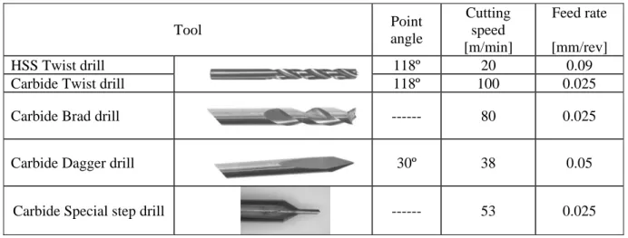
according to experimental results. Finally a ‘best set’ was selected for each tool used. Five types of drills and two tool materials were experimented for comparison: twist drill in both HSS and tungsten carbide, while the brad, dagger and special step drills were all in tungsten carbide only. Relevant machining parameters are shown in Table 2.
Twist drill is a standard geometry tool. Associated with the use of the twist drill, a pilot hole of 1.1 mm diameter was previously performed. The intention of that pilot hole was to reduce the maximum thrust force achieved and decrease delamination around the hole by cancelling the chisel edge effect of the drill. The use of HSS has the purpose of confirming the general idea that this material is not adequate for fibre reinforced composites drilling. Brad drill is a special edged drill firstly designed for cutting wood, with edges in scythe shape, that causes the tensioning of the fibres prior to cut, thus enabling a ‘clean cut’ and a smooth machined surface. Dagger drills are designed for fibre reinforced laminates and had a very sharp tip – 30º – in order to reduce the indentation effect. Due to its particular geometry it needs to have enough space at the exit side of the plate, which sometimes is not available, limiting its application in field work. The special step drill follows a suggestion from Dharan, during a conference on composites machining [20] that was developed in the aim of a PhD work in 2005 [21]. This special tool has two drilling diameters – 1.25 and 6 mm – dividing the drilling operation, and consequently the thrust force, in two stages. This division of the drilling operation also cancels the chisel edge effect for the final hole diameter drilling. The diameter transition has a conical shape, for a soft transition. The reduction of delamination risk by reducing the maximum thrust force is also looked for. Another advantage of this tool is the possibility of executing the hole in one operation only. A drawback of its geometry is the need for enough space available at the exit side of the plate, just like Dagger drills. Tool Point angle Cutting speed [m/min] Feed rate [mm/rev] HSS Twist drill 118º 20 0.09
Carbide Twist drill 118º 100 0.025
Carbide Brad drill --- 80 0.025
Carbide Dagger drill 30º 38 0.05
Carbide Special step drill --- 53 0.025
Table 2 : Tools used and relevant machining parameters.
Axial thrust force, Fz, and torque, Mt, during drilling were monitored using a Kistler 4782 dynamometer
associated to a multichannel amplifier and a personal computer for data acquisition. All the plates were drilled without the use of a sacrificial plate.
2.2 Delamination measurement
2.2.1 Images acquired by radiography
Delamination extension is not possible to be measured by a visual inspection as carbon/epoxy plates are opaque. Consequently, the plates need to be inspected by enhanced radiography. Delamination may be detected with this technique by previously using a contrasting fluid, like di-iodomethane. For that it is necessary to immerse the plate in the contrasting fluid for one and a half hour in a dark chamber. After this time interval, the plates are cleaned and radiographed. Example of final results of developed films can be seen at Figure 4.
a) b) c) d) Figure 4: Radiographies of drilled parts using: a) twist drill; b) Brad drill; c) Dagger drill; d) Special step
drill.
The resulting images were then processed and analysed using a previously developed image processing and analysis platform [22, 23], that integrates usual Computational Vision techniques, like for image filtering, segmentation and region analysis [24, 25, 26]. The use of that computational platform has the main purpose of reckoning from the images acquired by radiography, information regarding the damaged region, in particular the associated areas and diameters. This process has the advantage of reducing operator dependence to obtain the dimensions wanted, thus increasing the results reliability and confidence.
a) Original image (25% reduced).
b) Interest zone (100%). c) After smoothing.
d) After binarization. e) After morphological filters applied.
f) Region identification and measurement results.
Figure 5: Example of the determination of damage measurements in a radiography image by using image processing and analysis techniques [22, 23].
For radiographic images, the first step was the manual selection of the interest zone, in order to reduce computer processing time (Figure 5a) and 5b)). Then it was necessary to pre-process the resulting sub-image by using a smoothing filter to reduce sudden changes of intensity, associated to imaging noise (Figure 5c)); for that, we used a mean filter of size 3x3. Then, the smoothed image was binarized (Figure 5d)), using an automatically binarization algorithm based on adaptive threshold [22, 23]. As this step can originate a large number of regions it was followed by the elimination of those that were not relevant by the application of erosion and dilation morphological filters. After this step, each image was composed of the damaged region and its background (Figure 5e)). The final step was the use of a region processing and analysis algorithm to discriminate the different regions presented in each image. From each region the required measurements were obtained, particularly on the damaged region.
With the referred image processing and analysis pipeline it was possible to obtain the requested dimensions in order to have a damage evaluation according to equations (1) or (2). And so, were determined results considering the two criteria mentioned. In Figure 5, is presented an example of the use of our image processing and analysis pipeline on a radiographic image.
2.2.2 Images acquired by ultrasonic scanning
Besides radiography, another image modality commonly used to inspect internal damaged areas of a composite laminate is ultrasonic scanning, also a non-destructive technique. In ultrasonic inspection is employed a sound wave whose frequency is above the upper limit of audibility (20 kHz), usually in the range of 1 to 50 MHz. The sound wave propagates through the material at a certain speed, which is function of its properties; manly, of its density and elasticity. Sound waves are modified during their propagation by the boundaries encountered, by the material itself and by the presence of defects [27]. Delaminations, as they are orientated at right angles to an ultrasonic wave propagating at normal incidence to a laminate, are ideally aligned for detection by ultrasonic scanning. In this work, the images considered were acquired using a 5 MHz transducer.
For ultrasonic scanning images the image processing and analysis pipeline used was slightly different from the one described above. The first step was, as before, the selection of the interest zone (Figure 6a) and 6b)). Each copped colour image was then converted into the corresponding grey levels (Figure 6c)). After this conversion was done, pixels that were not included in the interest zones were removed (Figure 6d)). For this procedure a threshold operation was used by selecting an adequate threshold level, and pixels that had a grey level below that level were classified as noise pixels and removed from the input image (Figure 6e)). After this operation, the thresholded images were binarized, using the automatically binarization algorithm already referred [22, 23], and subjected to the application of morphological filters to get homogeneous regions (Figure 6f)). The final processing step was the same as for the radiography images; namely, the application of a region analysis algorithm to obtain the desired measurements. In Figure 6, an example of the interest zone, damage area identification and measurement results is presented.
2.3 Bearing test
The last phase of the experimental work done reported in this paper was the execution of the bearing test. As already referred, the main purpose of hole making in a plate is to assemble it to other parts in a structure. Therefore, it is important to know the load carrying capacity of a plate. This test was designed to determine the bearing response of multidirectional polymer matrix reinforced composite laminates and it follows the orientations determined in ASTM D5961-01 [17] standard test method. This procedure provides data for compare the effect of several machining methods used in this work. The tests were carried out at an INSTRON 4208 with a cutting speed of 2 mm/min. Deformation data was collected by two independent systems: one connected to the test machine and another from two LVDT installed at the test jig and connected to the plate. In order to have a valid test, a maximum load followed by a 30% decrease should be noticed, before shear out of the plate. Valid test results were then plotted against data arising from the two delamination criteria previously referred.
a) Original image (25% reduced).
b) Interest zone (100%). c) After gray levels conversion.
d) After noise pixels removal.
e) After binarization. f) After morphological filters applied.
g) Damage area identification and some measurement results.
Figure 6: Example of the determination of damage measurements in an ultrasonic scanning image.
3 Results
The results considered in this work were the maximum thrust force and torque during drilling, evaluation of delamination based on the criteria referred as Delamination Factor, equation (1), and Damage Ratio, equation (2) and finally by the bearing stress test values.
Maximum thrust force Maximum torque Bearing stress
Tool [N] [Nm] [MPa] HSS twist Avg - 104 Max - 108; min - 102 Avg - 0.22 Max – 0.24; min – 0.18 Avg - 709 Max - 726; min - 684 Carbide twist Avg - 28
Max – 29; min - 28
Avg - 0.34 Max – 0.39; min – 0.30
Avg - 748 Max - 755; min – 739 Carbide Brad Avg - 42
Max - 44; min – 40
Avg - 0.16 Max – 0.18; min – 0.14
Avg - 733 Max - 754; min – 714 Carbide Dagger Avg - 52
Max - 54; min - 58
Avg - 0.31 Max – 0.34; min – 0.28
Avg - 728 Max - 737; min – 717 Special step Avg - 43
Max - 44; min - 41
Avg - 0.49 Max – 0.56; min – 0.39
Avg - 764 Max - 767; min – 745 Table 3: Drill geometry comparison results (Avg – average; Max – higher value; min – lowest value)
Thrust force and torque data obtained during drilling are presented in Table 3. In the same table the results of the bearing stress for each tool are also shown. These values are the average of five tests under identical experimental conditions for the geometry of each tool considered in this study.
From the results presented it is possible to observe that there is a substantial difference when comparing HSS to carbide twist drills. The thrust force has a strong reduction and the bearing stress of the plate notably increases. Although some of these effects can be explained by the use of different cutting parameters, it must be reminded that those were optimized for each drill geometry and material prior to the experimental work here described. Comparing the results of the thrust force with bearing stress, it can be said that a reduction of the thrust force during drilling, thus reducing the risk of delamination onset, has resulted in higher values of the bearing stress. Clearly, drill geometry has a definitive influence on machined hole quality, affecting properties of plates to be assembled in a structure. A 14% difference was found when comparing the better individual value of bearing stress with the worst one. When considering average values, this difference comes to 7% between special step and HSS twist drill, which has always the worst results.
1.121 1.103 1.115 1.116 1.114 1.000 1.050 1.100 1.150 HSS twist Carbide twist Brad Dagger Special step Delamination Factor (Fd)
Figure 7: Comparison of the delamination factor for several tools.
Torque values are always low for all drills considered and no influence on delamination, or any other damage, was identified as relevant.
After drilling, the plates were radiographed and the images processed and analysed as described in 2.2. The results from the application of the image processing and analysis techniques considered are presented in Figure 7, considering Delamination Factor criteria and a nominal hole diameter of 6 mm.
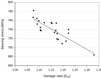
660 680 700 720 740 760 780 800 1,00 1,05 1,10 1,15 1,20 1,25 1,30 1,35 Damage ratio [Drat]
B eari ng s tres s [ M P a ]
A relation connecting damage ratio and bearing stress was established from the data collected during the experimental work done. This relation can be seen in Figure 8, with a correlation factor higher than 0.8. A second relation linking delamination factor to bearing stress was also setup, although the correlation factor was lower (around 0.5). In both cases a linear correlation was tried, returning a line with negative slope. This slope confirms that delamination is an important factor in load carrying capacity of a laminate plate with assembly by screws, rivets or bolts.
From the data in Figure 8, and the results of Table 3, it is possible to say that higher thrust forces during drilling lead to higher delamination around the hole and, consequently, a decrease in plate mechanical strength, as given by bearing stress test results. It was evident that the higher values of bearing stress correspond to the plates with lower delamination.
4
Conclusions
Five different tools for drilling hybrid laminates were compared in this work, one of them in HSS and the others in tungsten carbide. These four carbide drills had different geometries: twist, brad, dagger and a special step design. With such purpose a laminate with two types of reinforcement – carbon and glass – fibres in an epoxy matrix was drilled using the tools mentioned. Each drill was used at the cutting parameters considered as ‘best set’. Forces were monitored during drilling, delamination evaluated through radiography and ultrasonic scanning associated with an image processing and analysis platform. Finally, drilled laminate strength was measured by a bearing test.
Based on the experimental work presented it is possible to draw some conclusions:
• Delamination damage can be reduced by a proper combination of tool, cutting speed and feed rate. This damage can be evaluated by a non-destructive test like enhanced radiography or ultrasonic scanning.
• From the drills experimented, HSS twist drill had the lowest results, showing the inadequacy of the use of this material in drilling tools for fiber reinforced plastics.
• Carbide twist drill had the best results for thrust force and Delamination Factor, but the bearing stress test results were lower by about 2% from the best one.
• Special step drilled plates had the higher results of bearing stress (Table 3), although these plates do not have the lower delamination factor value (Figure 7).
• The image processing and analysis techniques considered in this work showed to be adequate to identify and qyuantify the image regions involved. Their use can be easily extended to other materials that are suitable to be radiographed, C-scanned or examined by any other imaging modelities
• Delamination extension can be correlated with bearing stress showing that higher delamination has a correspondence with lower bearing stresses.
• The relationships vary if a different composite laminate – material or stacking sequence – is used. This has to be present when designing a structure using fibre reinforced laminates.
References
[1] A. Langella, L. Nele, A. Maio, “A torque and thrust prediction model for drilling of composite
materials”, Composites A, 36, pp. 83-93, 2005.
[2] E. Persson, I. Eriksson, L. Zackrisson, “Effects of hole machining defects on strength and fatigue life
of composite laminates”, Composites A, 28, pp. 141-151, 1997.
[3] S. Abrate, Machining of Composite Materials, Composites Engineering Handbook, Ed. P. K. Mallick, Marcel Dekker, New York, pp. 777-809, 1997.
[4] H. Hocheng, C. K. H. Dharan, “Delamination during drilling in composite laminates”, J. of
[5] R. Piquet, B. Ferret, F. Lachaud, P. Swider, “Experimental analysis of drilling damage in thin
carbon/epoxy plate using special drills”, Composites A, 31, pp. 1107-1115, 2000.
[6] K. Y. Park, J. H. Choi, D. G. Lee, “Delamination-free and high efficiency drilling of carbon fiber
reinforced plastics”, J. of Composite Materials, 29, pp. 1988-2002, 1995.
[7] C. H. K. Dharan, M. S. Won, “Machining parameters for an intelligent machining system for
composite laminates”, Int. J. of Machine Tools and Manufacture, 39, pp. 415-426, 2000.
[8] R. Stone, K. Krishnamurthy, “A Neural Network Thrust Force Controller to Minimize Delamination
During Drilling of Graphite-Epoxy Composites”, Int. J. Machine Tools and Manufacture, 36, pp.
985-1003, 1996.
[9] C. C. Tsao, H. Hocheng, ”Taguchi analysis of delamination associated with various drill bits in
drilling of composite material”, Int. J. of Machine Tools and Manufacture, 44, pp. 1085-1090, 2004.
[10] J. P. Davim, P. Reis, “Furação de laminados epóxidos reforçados a fibras de carbono (CFRP):
relação entre as forças de corte e o factor de delaminagem”, VI Congr. Ibero-Americano de Engenharia Mecânica, Coimbra, pp. 1079-1084, 2003.
[11] H. Hocheng, C. C. Tsao, “The path towards delamination-free drilling of composite materials”, J. of
Materials Processing Technology, 167, pp. 251-264, 2005.
[12] M. S. Won, C. H. K. Dharan, “Chisel edge and pilot hole effects in drilling composite laminates”,
Trans. of ASME J. of Manufacturing Science and Engineering, 124, pp. 242-247, 2002.
[13] C. C. Tsao, H. Hocheng, ”The effect of chisel length and associated pilot hole on delamination when
drilling composite materials”, Int. J. of Machine Tools and Manufacture, 43, pp. 1087-1092, 2003.
[14] W. C. Chen, “Some experimental investigations in the drilling of carbon fibre-reinforced plastic
(CFRP) composite laminates”, Int. J. of Machine Tools and Manufacture, 37, pp. 1097-1108, 1997.
[15] M. Mehta, M. ,T. J. Reinhart, A. H. Soni, “Effect of fastener hole drilling anomalies on structural
integrity of PMR-15/Gr composite laminates”, Proc. of the Machining Composite Materials Symposium, ASM Materials Week, pp. 113-126, 1992.
[16] C. C. Tsao, H. Hocheng, “Computerized tomography and C-Scan for measuring delamination in the
drilling of composite materials using various drills”, Int. J. of Machine Tools and Manufacture, 45,
pp. 1282-1287, 2005.
[17] ASTM D5961-01, “Standard Test Method for bearing response of polymer matrix composite
laminates”, ASTM International, 2001
[18] M. M. Schwartz, Composite Materials Handbook, McGraw Hill, 1988.
[19] M. G. Bader, “Hybrid effect”, Handbook of Polymer-fibre Composites, Longman Scientific Technical, pp. 225-230, 1994.
[20] C. K. H. Dharan, “Conference on composites machining”, INEGI-PORTO, 2000. [21] L. M. P. Durão, “Machining of Hybrid Composites”, PhD. thesis, FEUP, Porto, 2005.
[22] J. M. R. S. Tavares, PhD. thesis: “Análise de Movimento de Corpos Deformáveis usando Visão
Computacional”, FEUP, Porto, 2000.
[23] J. M. R. S. Tavares, J. G. Barbosa, A. J. Padilha, “Apresentação de um Banco de Desenvolvimento e
Ensaio para Objectos Deformáveis”, RESI – Revista Electrónica de Sistemas de Informação, vol. 1,
2002.
[24] G. W. Awcock, R. Thomas, “Applied image processing”, McGRAW-HILL International Editions, New York, 1995.
[25] R. Jain, R. Kasturi, B. G. Schunck, “Machine Vision”, McGRAW-HILL International Editions, New York, 1995.
[26] R. J. Schalkoff, “Digital image processing and computer vision”, John Willey & Sons, Inc., 1989. [27] R. A. Smith, “An introduction to the ultrasonic inspection of composites”, Non-destructive testing of


![Figure 5: Example of the determination of damage measurements in a radiography image by using image processing and analysis techniques [22, 23]](https://thumb-eu.123doks.com/thumbv2/123dok_br/19178692.944312/6.892.159.747.438.1072/figure-example-determination-measurements-radiography-processing-analysis-techniques.webp)