xx/xx
https://doi.org/10.5028/jatm.v11.999 ORIGINAL PAPER
1.Malek-Ashtar University of Technology – Aerospace Engineering – Department of Aerospace Engineering – Lavizan/Tehran – Iran. 2.Amirkabir University of Technology – Aerospace Engineering – Department of Aerospace Engineering – Hafez/Tehran – Iran.
3.Malek-Ashtar University of Technology – Electrical and Control Engineering – Department of Electrical Engineering – Tehran/Tehran – Iran.
ABSTRACT: The structure of mission management and maneuver planning for multiple UAVs in close formation fl ight is investigated. This article provides a distributed and priority-based platform of guidance and control model to meet requirements for each coordinated maneuver. To accomplish the coordinated maneuvers of multiple UAVs, some levels of hierarchy from mission planning to accurate guidance law are presented. The main focuses have been on the structure of equations and vicinity pattern to avoid a probable collision during maneuver so the high-level decision-maker can integrate all irregularities and solve them at the same time. Unlike complex control systems, the proposed algorithm provides outstanding following performance and inherent collision avoidance pattern due to prioritized tracking. The results show the admissible performance of the framework designed for implementing coordinated maneuvers due to its lower collision probability and noise resistance. According to the simulations, this method also resolves irregularity and disarrangements in the close formation fl ights and tracking media.
KEYWORDS: Hierarchical framework, Guidance and control, Coordinated maneuver, Multi-UAV system, Maneuver planning.
INTRODUCTION
Unmanned aerial vehicle (UAV) systems are becoming increasingly important as being capable of performing hazardous tasks which have been previously performed by manned planes and consequently the eff orts spent on human labor and economic cost can be reduced. Th e problem of an autonomous formation fl ight of UAV has been widely studied. Th e aerodynamic benefi ts of formation fl ight, particularly close formation fl ight, have been more studied (Zhang and Liu 2017). Th e investigation of control issues related to a leader-wingman formation has led to the introduction of diff erent compensation type controllers (Wang and Wang 2017). Oh et al. (2015) addressed dynamic modeling and formation fl ight control considering aerodynamic eff ects due to the vortices. Xue and Cai (2016) proposed a formation fl ight control scheme based on the concept of formation geometry center, also known as the formation virtual leader with communication constraints. Yang et al. (2004) and Min and Tahk (2005) addressed the formation-keeping control problem for the three-dimensional autonomous formation fl ight.
A Hierarchical and Prioritized Framework
in Coordinated Maneuver of Multiple UAVs
Based on Guidance Regulator
Hassan Haghighi1,2*, Seyed Hossein Sadati1, Jalal Kar imi1, Mohammad Mehdi Dehghan3
Haghighi H; Sadati SH; Karimi J; Dehghan MM (2019) A Hierarchical and Prioritized Framework in Coordinated Maneuver of Multiple UAVs Based on Guidance Regulator. J Aerosp Technol Manag, 11: e1119. https://doi.org/10.5028/ jatm.v11.999
How to cite
J. Aerosp. Technol. Manag., São José dos Campos, v11, e1119, 2019 Haghighi H; Sadati SH; Karimi J; Dehghan MM xx/xx
02/18
In order to achieve the desired level of performance and maneuverability, one needs to provide both the required piloting ability (i.e. reflexive skills, typically achieved through a low-level feedback control system) and a high-level knowledge of the vehicle’s set of achievable behaviors (Stengel 1993). Frazzoli (2002) focused on the high-level component in the planning process, presenting a framework by which the motion plan for a single vehicle is generated through the selection of a sequence of well-defined motion primitives, or behaviors. A more complicated version of the same problem must be solved when it is desired that several UAVs cooperate closely during the mission. In general, when many aircrafts operate in the same airspace, some level of coordination between them is required to ensure a variety of objectives: from basic collision avoidance including conflict detection and resolution to formation control, multiple target tracking, and synchronization issues (Frazzoli 2002; Zhao and Zhou 2016). Although these investigations cover a variety of coordination and maneuverability problems, the general management and decision maker units have not been well reflected.
In tracking media different methods have been investigated. Park et al. (2004) investigated linear controllers and nonlinear logic guidance (NGL) to track the desired path. The linear controllers are not well adapted in nonlinear maneuvers so they derived more accurate tracker by NGL. Shah et al. (2015) studied a geometrical pattern due to sliding mode guidance for aerial tracking problem. The authors generate the desired roll angle by nonlinear sliding mode guidance law. The main difficulty of this method is defining the proper sliding surface to satisfy all of the flight conditions and maneuvers. Ali et al. (2016) also designed a sliding mode controller for lateral control of one UAV on waypoint-based paths; there is no investigation about controller sensitivity due to parametrical uncertainty. Sadeghi et al. (2015) and Gavilan et al. (2015) proposed a dynamic inversion, backstepping, and model predictive control to follow the desired path by one fixed-wing UAV. Although having proper tracking, these methods have a high dependency on estimated vehicle dynamic model and are very sensitive to surrounding disturbance and noise. Kumaresan and Singh (2016) focused on nonmodel-based decentralized formation using modified pursuit guidance control by three UAVs in the 2D environment. Their work is similar to ours in the basic concept but the normal and tangential acceleration commands are given to the inner loop are not optimal.
We can divide the previous works into two categories: first, investigate about formation execution and its restriction like collision avoidance, bandwidth, connection distance, control scheme; second, study the application media and form presentation like maneuverability, search and surveillance, configuration and arrangement basis. We are looking for a simple and applicable literary design to link these two categories. Most of the previous results are restricted to 2D formation problems and full nonlinear dynamics of the aircraft model is not reflected perfectly. Also, it cannot guarantee the performance of the formation form conservation while the leader maneuvers with lateral acceleration. In our approach, a global command block based on hierarchical process makes the necessary decisions. The maneuver structure is executed in priority order according to the instructions given out in the hierarchical command block. Regarding managerial defects of previous studies, the proposed approach provides more coordination between agents, appropriate decision making in hazardous situations such as leader missing and inherent collision avoidance due to priority-based motions. The main contributions of this approach can be summarized as follows: first, to design a hierarchical framework to coordinate all activities; second, maneuver design while proposing a consensus and priority-based formation flight control protocol that enables the multi-UAV system to maintain a geometric formation flight with the specified network topology. Like other studies, the topologies discussed here may not connect all the time but the union of the topologies is connected in each period of time. The multi-UAV planning can shape and maintain the expected formation (V-type formation consist of 5 UAVs) with the desired velocity when it satisfies the sufficient condition.
HIERARCHICAL AND PRIORITIZED TRACKING SYSTEM
J. Aerosp. Technol. Manag., São José dos Campos, v11, e1119, 2019 A Hierarchical and Prioritized Framework in Coordinated Maneuver of Multiple UAVs Based on Guidance Regulator
xx/xx
03/18
altitudes and velocity vectors have the same manner to change. To prevent complexity, a general strategy needs to be selected for all UAVs in a formation.
TRACKING STRATEGY
Step 1: Hierarchical Framework
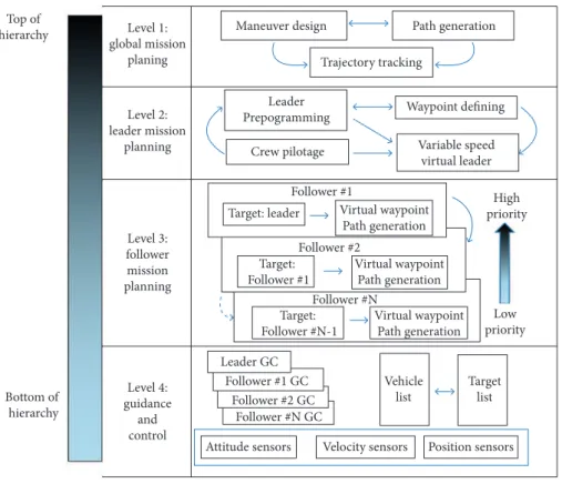
The hierarchical design of large-scale multi-vehicle consists of several scenarios of tasks at the formation. According to the prioritized agents and maneuver activity, the trajectory for each vehicle is generated by the hierarchical decision maker. The constructing techniques of this method are illustrated in Fig. 1.
Figure 1. Hierarchical design of large-scale multi-vehicle autonomous systems.
The hierarchical architecture features an upper level with global mission planning (GMP) and leader mission planning (LMP); a middle level with local agent tracking as well as formation design; a low level that interfaces with onboard baseline controllers and GC module. As shown in Fig. 1, for certain maneuvers, leader mission planning are specified after maneuver design or path generation by leader preprogramming or ground crew pilotage. Maneuver design in relation to path generation process is designed to create a reference pattern to perform the desired strategy for all UAVs. So in leader/follower mission planning (FMP) level, the tracking mission becomes clear. Agents follow the global or local leader on a decentralized priority basis. The hierarchical generated path (GP) is formulated as Eq. 1.
𝐺𝐺𝐺𝐺#= 𝐺𝐺𝐺𝐺𝐺𝐺
⎝ ⎜ ⎜ ⎛
𝐿𝐿𝐺𝐺𝐺𝐺 ⎝ ⎜ ⎜ ⎛
𝐹𝐹𝐺𝐺𝐺𝐺 ⎝ ⎜ ⎛
𝐺𝐺𝐺𝐺
,-𝑎𝑎𝑎𝑎𝑎𝑎𝑎𝑎𝑎𝑎#1 𝑎𝑎𝑎𝑎𝑎𝑎𝑎𝑎𝑎𝑎#2
⋮ 𝑎𝑎𝑎𝑎𝑎𝑎𝑎𝑎𝑎𝑎#𝑎𝑎
78 ⎠ ⎟ ⎞
⎠ ⎟ ⎟ ⎞
⎠ ⎟ ⎟ ⎞
𝑖𝑖 ∈ {1,2, … , 𝑎𝑎}
𝑇𝑇CD
𝐺𝐺𝐺𝐺#= 𝑇𝑇CDE𝑇𝑇CDFGH… I𝑇𝑇CJK𝑇𝑇CG(𝑇𝑇M)OPQR
(1)
Level 3: follower mission planning
Path generation Level 1:
global mission planing Top of
hierarchy
Bottom of hierarchy
Level 2: leader mission
planning
Level 4: guidance
and control
Maneuver design
Trajectory tracking
Leader Prepogramming
Target: leader
Target: Follower #1
Target: Follower #N-1
Virtual waypoint Path generation
Virtual waypoint Path generation
Virtual waypoint Path generation
High priority
Vehicle list
Low priority
Target list
Attitude sensors Velocity sensors Position sensors Follower #1
Follower #1 GC Follower #2 GC
Follower #N GC Leader GC
Follower #2
Follower #N
Variable speed virtual leader Crew pilotage
J. Aerosp. Technol. Manag., São José dos Campos, v11, e1119, 2019 Haghighi H; Sadati SH; Karimi J; Dehghan MM xx/xx
04/18
The GP is a trajectory vector (i ∈ {1, 2, ..., n}). The GC processing acts as a priority function of agent trajectories. So the trajectory of i-th follower (TFi ) is a combinational function of higher priority agents. The GC of i-th agent (GCi) to apply in Eq. 1, denotes as Eq. 2.
7
𝐺𝐺𝐺𝐺
#= 𝐺𝐺𝐺𝐺𝐺𝐺
⎝
⎜
⎜
⎛
𝐿𝐿𝐺𝐺𝐺𝐺
⎝
⎜
⎜
⎛
𝐹𝐹𝐺𝐺𝐺𝐺
⎝
⎜
⎛
𝐺𝐺𝐺𝐺
,-𝑎𝑎𝑎𝑎𝑎𝑎𝑎𝑎𝑎𝑎#1
𝑎𝑎𝑎𝑎𝑎𝑎𝑎𝑎𝑎𝑎#2
⋮
𝑎𝑎𝑎𝑎𝑎𝑎𝑎𝑎𝑎𝑎#𝑎𝑎
78
⎠
⎟
⎞
⎠
⎟
⎟
⎞
⎠
⎟
⎟
⎞
𝑖𝑖 ∈ {1,2, … , 𝑎𝑎}
𝑇𝑇
CD𝐺𝐺𝐺𝐺
#= 𝑇𝑇
CDE𝑇𝑇
CDFGH… I𝑇𝑇
CJK𝑇𝑇
CG(𝑇𝑇
M)OPQR
(2)In the autonomous form, the leader produces its command from the time-independent variable speed virtual leader (Liu et al. 2013) through predefined or maneuver path. Virtual leader, in contrast to the leader, is the point that wingman UAV have to follow and is produced by a leader in the fixed distance. In prioritized tracking, the arrangement of virtual leaders is designed by mission planning in certain and leader-independent ways. In this strategy, each UAV produces a virtual waypoint for lower priority agents. In guidance and control level a priority-based architecture operates the desired commands due to sensor and visibility instruments.
Step 2: Tracking Framework
The design needs to be synchronized with path tracking and following patterns. Using a classical guidance law is a useful strategy in the following process due to its low computational complexity and suitable performance. The lateral accelerations are used for correct tracking errors when two or multi-UAVs are flying at the same speed so the guidance law and related control commands should produce appropriate accelerations. Exploiting the synergistic coupling that exists between the guidance and flight control functions helps to achieve optimal tracking performance. In contrast to the decoupled approach, a GC paradigm facilitates synergism in addition to offering a structured approach to performance optimization. Figure 2 illustrates a notional GC architecture. Adjust output parameters for suitable use in the guidance system is the main part of the controlling system so an additional controller is required in the outer loop for autopilot and actuator section (Sadeghi et al. 2015).
Figure 2.Tracking framework.
Guidance section of GC is design-based on pure pursuit (PP) parameters. PP law makes the follower approach leader by the shortest lateral path in vector view tracking. According to minimum structural equipment, PP creates a rule that keeps the follower velocity vector in the direction of the line of sight (LOS). Thus, UAV will not dismiss the leader so there would be no need to apply camera stabilizer and heavy equipment to keep continuously reference point tracking.
In spite of such dynamically changing conditions, vehicles in an autonomous team should maintain close distance and attitude with others in order to avoid collisions. In order to reach these goals, two different types of leader-follower approaches have been
Maneuver design
Leader motion
Guidance law Leader
attitude
Attitude control Target
sensors
Actuation commands
Inertial navigation
UAV 6DOF dynamic Longitude
velocity control
J. Aerosp. Technol. Manag., São José dos Campos, v11, e1119, 2019 A Hierarchical and Prioritized Framework in Coordinated Maneuver of Multiple UAVs Based on Guidance Regulator
xx/xx
05/18
adopted. First, closer to the architecture of the classical network, establishes a fixed pattern due to the leader position. A fixed distance from leader specifies the reference location for other agents. Each UAV try to reach this relative distance independently. Second, perform a priority architecture due to a hierarchical structure and routes data in the dependent traversing. Each UAV follows the local leader according to the priority structure. In this type, some levels of the hierarchy are needed to reach the destination. Figure 3 illustrates the first approach for the agents located in the left-hand of the leader and the second approach for the right-hand UAVs.
Figure 3.Two tracking strategies according to PP guidance inspiration. Left: without priority; Right: with priority.
According to the PP guidance inspiration, some collision avoidance roles are inherently considered in the priority hierarchical tracking. Figure 4 shows the major critical situation. Left-hand tracking (without priority) leads to a collision at the moment of approximation (Fig. 4a) while right-hand tracking has its critical situation where higher priority UAV is located in the LOS between lower priority UAV and virtual waypoint at the moment of approximation in the time t. so in the next moment, the strategy leads to no collision term with a higher probability, as shown in Fig. 4b.
Figure 4.Tracking approaches at the moment of approximation a) without agent priority; and b) with agent priority.
To derive the main equations, the state and control parameters should be defined according to problem requirements. The following nonlinear equations can express the plant model (Eqs. 3 to 5):
𝑥𝑥̇(𝑡𝑡) = 𝑓𝑓(𝑥𝑥, 𝑡𝑡) + 𝑏𝑏(𝑥𝑥, 𝑡𝑡)𝑢𝑢(𝑡𝑡) + 𝑐𝑐(𝑥𝑥, 𝑡𝑡)𝑤𝑤(𝑡𝑡)
𝑦𝑦(𝑡𝑡) = 𝑑𝑑(𝑥𝑥, 𝑡𝑡) + 𝑒𝑒(𝑥𝑥, 𝑡𝑡)𝑤𝑤(𝑡𝑡)
𝑧𝑧(𝑡𝑡) = 𝑔𝑔(𝑥𝑥, 𝑡𝑡) + ℎ(𝑥𝑥, 𝑡𝑡)𝑢𝑢(𝑡𝑡)
𝑥𝑥(𝑡𝑡) ∈ ℝ
`𝑢𝑢(𝑡𝑡) ∈ ℝ
a𝑤𝑤(𝑡𝑡) ∈ ℝ
b𝑦𝑦(𝑡𝑡) ∈ ℝ
c𝑧𝑧(𝑡𝑡) ∈ ℝ
d𝑥𝑥̇(𝑡𝑡) = 𝑓𝑓(𝑥𝑥, 𝑡𝑡) + 𝑏𝑏(𝑥𝑥, 𝑡𝑡)𝑢𝑢(𝑡𝑡) + 𝑐𝑐(𝑥𝑥, 𝑡𝑡)𝑤𝑤(𝑡𝑡)
𝑦𝑦(𝑡𝑡) = 𝑑𝑑(𝑥𝑥, 𝑡𝑡) + 𝑒𝑒(𝑥𝑥, 𝑡𝑡)𝑤𝑤(𝑡𝑡)
𝑧𝑧(𝑡𝑡) = 𝑔𝑔(𝑥𝑥, 𝑡𝑡) + ℎ(𝑥𝑥, 𝑡𝑡)𝑢𝑢(𝑡𝑡)
𝑥𝑥(𝑡𝑡) ∈ ℝ
`𝑢𝑢(𝑡𝑡) ∈ ℝ
a𝑤𝑤(𝑡𝑡) ∈ ℝ
b𝑦𝑦(𝑡𝑡) ∈ ℝ
c𝑧𝑧(𝑡𝑡) ∈ ℝ
d(3) (a)
(4)
Visual leader Initial position Final position Pure pursuit arrow High priority UAV Low priority UAV Leader
Right
Left 2
2
1
1
Leader t + t0
t + t0 t + t0
t + t0
t + t 0 t + t
0
t + t0 t
t
t
t
t t
t t
2
2
2
1
1
1
J. Aerosp. Technol. Manag., São José dos Campos, v11, e1119, 2019 Haghighi H; Sadati SH; Karimi J; Dehghan MM xx/xx
Equation 3 describes a nonlinear plant with state vector , driven by control input vector and subjected to a set of exogenous input variables represented by vector , which include disturbances to be rejected and possibly references to be tracked. Equation 4 defines a set of measured variables represented by vector , which are functions of x(t) and w(t). Finally, Eq. 5 defines the performance output vector . The performance output parameters are specified to be those components of the state and control vectors deemed crucial to the design problem. The terms f(x, t), b(x, t), d(x, t), g(x, t), and h(x, t) are nonlinear vector functions, and c(x, t) and e(x, t) are matrices of appropriate dimensions, state vectors dependent. Hence the model has been defined; it must be brought to the state-dependent form. According to the tracking pattern, an overview of the state x(t), measurement y(t), control u(t), and performance output z(t) vectors is given in Eq. 6:
10
𝑥𝑥̇(𝑡𝑡) = 𝑓𝑓(𝑥𝑥, 𝑡𝑡) + 𝑏𝑏(𝑥𝑥, 𝑡𝑡)𝑢𝑢(𝑡𝑡) + 𝑐𝑐(𝑥𝑥, 𝑡𝑡)𝑤𝑤(𝑡𝑡)
𝑦𝑦(𝑡𝑡) = 𝑑𝑑(𝑥𝑥, 𝑡𝑡) + 𝑒𝑒(𝑥𝑥, 𝑡𝑡)𝑤𝑤(𝑡𝑡)
𝑧𝑧(𝑡𝑡) = 𝑔𝑔(𝑥𝑥, 𝑡𝑡) + ℎ(𝑥𝑥, 𝑡𝑡)𝑢𝑢(𝑡𝑡)
𝑥𝑥(𝑡𝑡) ∈ ℝ
`𝑢𝑢(𝑡𝑡) ∈ ℝ
a𝑤𝑤(𝑡𝑡) ∈ ℝ
b𝑦𝑦(𝑡𝑡) ∈ ℝ
c𝑧𝑧(𝑡𝑡) ∈ ℝ
d11
𝑥𝑥
e(𝑡𝑡) =
⎣
⎢
⎢
⎢
⎡𝑅𝑅
̇
jklm(𝑡𝑡)
𝑅𝑅
jklm(𝑡𝑡)
𝑎𝑎
Mm(𝑡𝑡)
𝑉𝑉
Mm(𝑡𝑡) ⎦
⎥
⎥
⎥
⎤
𝑥𝑥
s(𝑡𝑡) =
⎣
⎢
⎢
⎢
⎢
⎢
⎢
⎢
⎢
⎡𝑉𝑉
𝛼𝛼(𝑡𝑡)
(𝑡𝑡)
𝛽𝛽(𝑡𝑡)
𝜙𝜙(𝑡𝑡)
𝜃𝜃(𝑡𝑡)
𝜓𝜓(𝑡𝑡)
𝑝𝑝(𝑡𝑡)
𝑞𝑞(𝑡𝑡)
𝑟𝑟(𝑡𝑡)⎦
⎥
⎥
⎥
⎥
⎥
⎥
⎥
⎥
⎤
𝑥𝑥
|(𝑡𝑡) = [Θ
jkl] 𝑥𝑥(𝑡𝑡) = Ä
𝑥𝑥
e(𝑡𝑡)
𝑥𝑥
s(𝑡𝑡)
𝑥𝑥
|(𝑡𝑡)
Å
𝑦𝑦(𝑡𝑡) =
⎣
⎢
⎢
⎢
⎢
⎢
⎢
⎢
⎡𝑅𝑅
̇
jklm(𝑡𝑡)
𝑅𝑅
jklm(𝑡𝑡)
𝑎𝑎
Çm(𝑡𝑡)
𝑎𝑎(𝑡𝑡)
Θ
jkl𝑝𝑝(𝑡𝑡)
𝑞𝑞(𝑡𝑡)
𝑟𝑟(𝑡𝑡) ⎦
⎥
⎥
⎥
⎥
⎥
⎥
⎥
⎤
𝑢𝑢(𝑡𝑡) =
⎣
⎢
⎢
⎢
⎡
𝛿𝛿
𝛿𝛿
klkÑ#l
𝛿𝛿
jÖÜ𝛿𝛿
álÑà𝛿𝛿
â⎦
⎥
⎥
⎥
⎤
𝑧𝑧(𝑡𝑡) = ä𝑥𝑥
𝑢𝑢(𝑡𝑡)ã
(𝑡𝑡)
𝑅𝑅
jklm(𝑡𝑡))
𝑅𝑅̇
jklm(𝑡𝑡)
𝑎𝑎
Mm(𝑡𝑡)
𝑉𝑉
Mm(𝑡𝑡)
𝑎𝑎
Çm(𝑡𝑡)
11
𝑥𝑥
e(𝑡𝑡) =
⎣
⎢
⎢
⎢
⎡𝑅𝑅
̇
jklm(𝑡𝑡)
𝑅𝑅
jklm(𝑡𝑡)
𝑎𝑎
Mm(𝑡𝑡)
𝑉𝑉
Mm(𝑡𝑡) ⎦
⎥
⎥
⎥
⎤
𝑥𝑥
s(𝑡𝑡) =
⎣
⎢
⎢
⎢
⎢
⎢
⎢
⎢
⎢
⎡𝑉𝑉
𝛼𝛼(𝑡𝑡)
(𝑡𝑡)
𝛽𝛽(𝑡𝑡)
𝜙𝜙(𝑡𝑡)
𝜃𝜃(𝑡𝑡)
𝜓𝜓(𝑡𝑡)
𝑝𝑝(𝑡𝑡)
𝑞𝑞(𝑡𝑡)
𝑟𝑟(𝑡𝑡)⎦
⎥
⎥
⎥
⎥
⎥
⎥
⎥
⎥
⎤
𝑥𝑥
|(𝑡𝑡) = [Θ
jkl] 𝑥𝑥(𝑡𝑡) = Ä
𝑥𝑥
e(𝑡𝑡)
𝑥𝑥
s(𝑡𝑡)
𝑥𝑥
|(𝑡𝑡)
Å
𝑦𝑦(𝑡𝑡) =
⎣
⎢
⎢
⎢
⎢
⎢
⎢
⎢
⎡𝑅𝑅
̇
jklm(𝑡𝑡)
𝑅𝑅
jklm(𝑡𝑡)
𝑎𝑎
Çm(𝑡𝑡)
𝑎𝑎(𝑡𝑡)
Θ
jkl𝑝𝑝(𝑡𝑡)
𝑞𝑞(𝑡𝑡)
𝑟𝑟(𝑡𝑡) ⎦
⎥
⎥
⎥
⎥
⎥
⎥
⎥
⎤
𝑢𝑢(𝑡𝑡) =
⎣
⎢
⎢
⎢
⎡
𝛿𝛿
𝛿𝛿
klkÑ#l
𝛿𝛿
jÖÜ𝛿𝛿
álÑà𝛿𝛿
â⎦
⎥
⎥
⎥
⎤
𝑧𝑧(𝑡𝑡) = ä𝑥𝑥
𝑢𝑢(𝑡𝑡)ã
(𝑡𝑡)
𝑅𝑅
jklm(𝑡𝑡))
𝑅𝑅̇
jklm(𝑡𝑡)
𝑎𝑎
M
m
(𝑡𝑡)
𝑉𝑉
Mm
(𝑡𝑡)
𝑎𝑎
Çm(𝑡𝑡)
(5)
(6)
where x1(t) denotes the guidance parameter in the term of relative distances (RG
rel(t)) and velocity ( . RG
rel(t)), leader acceleration (a G
L(t)) and leader velocity (V G
L(t)) ; x2(t) represents body motion states; and x3(t) shows the relative attitude due to multi-agent
coordinated maneuver. In Eq. 6, a G
L(t) denotes the output acceleration of guidance unit as the reference command. These parameters must be solved for all UAVs during tracking and formation maneuvers, according to hierarchical structure as well as agent priority.
In the considered guidance and control method, pursuit guidance will produce a set of acceleration commands in the inertial coordination. When these commands are transferred in the UAV body coordination, the control reference commands will be produced and compared by the model output parameters. This method of implementation can be applied to all maneuvers. Maneuver attributes are presented in Eqs. 7 to 10.
J. Aerosp. Technol. Manag., São José dos Campos, v11, e1119, 2019 A Hierarchical and Prioritized Framework in Coordinated Maneuver of Multiple UAVs Based on Guidance Regulator
xx/xx
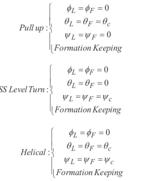
where R → is location vector in the inertial coordination system and R → ref reference distance vector in the inertial (ϕ, θ and ψ) axis. Subscript L, F and c assign parameters to leader, follower and reference commands of the control system, respectively. During the formation flight, formation-keeping process is concerned as an independent maneuver which have to tune reference parameter on the desired condition. Equation 11 shows this condition.
12
ï
î
ï
í
ì
®
-®
®
!
!
!
!
!
ï
ï
î
ï
ï
í
ì
=
=
=
=
=
=
Keeping
Formation
up
Pull
F L c F L F L0
0
:
y
y
q
q
q
f
f
ï
ï
î
ï
ï
í
ì
y
y
y
q
q
f
f
ï
ï
î
ï
ï
í
ì
y
y
y
q
q
q
f
f
12ï
î
ï
í
ì
®
-®
®
!
!
!
!
!
ï
ï
î
ï
ï
í
ì
y
y
q
q
q
f
f
ï
ï
î
ï
ï
í
ì
=
=
=
=
=
=
Keeping
Formation
Turn
Level
SS
c F L F L F Ly
y
y
q
q
f
f
0
0
:
ï
ï
î
ï
ï
í
ì
y
y
y
q
q
q
f
f
12ï
î
ï
í
ì
®
-®
®
!
!
!
!
!
ï
ï
î
ï
ï
í
ì
y
y
q
q
q
f
f
ï
ï
î
ï
ï
í
ì
y
y
y
q
q
f
f
ï
ï
î
ï
ï
í
ì
=
=
=
=
=
=
Keeping
Formation
Helical
c F L c F L F Ly
y
y
q
q
q
f
f
0
:
𝑅𝑅å⃗
𝑅𝑅å⃗
jkáϕ θ
ψ
ï
ï
î
ï
ï
í
ì
=
=
-=
-=
-F L ref F L ref F L ref F LV
V
Z
Z
Z
Y
Y
Y
X
X
X
Keeping
Formation
!
!
!
!
!
!
!
!
!
!
!
:
(8) (9) (10) (11)Additionally to the task of configuration, when the followers deviate from the reference path, guidance accelerations would have a value and return the UAVs to their desired position. Deviation from the desired position and following up the virtual leading point is presented in Fig. 5.
J. Aerosp. Technol. Manag., São José dos Campos, v11, e1119, 2019 Haghighi H; Sadati SH; Karimi J; Dehghan MM xx/xx
The coordination of virtual leader as a guidance reference point (Xref, Yref, Zref = 0) is expressed in the body coordinate system of the leader and the coordination of the follower is defined in the inertial NED system. Determining the relative distance between leader and follower (R) requires reference point to transfer from the body axis of the leader to NED. This transfer is shown in Eq. 12. Direction Cosine Matrix (DCM) is applied to transfer from the body axis to NED axis. The inputs of DCM are attitude parameters of the leader. Equation 13 shows the magnitude of the reference distance vector. In order to calculate the relative distance of guidance law (R), the vector of the reference point and coordinates of the leader are deduced in the NED frame as shown in Eq. 14.
14
𝑅𝑅å⃗
M𝑅𝑅å⃗
Cé𝑅𝑅å⃗
jkáé
[
]
ú
ú
ú
û
ù
ê
ê
ê
ë
é
=
ref ref ref NED refZ
Y
X
DCM
R
!
|
!
!
!
!
-÷÷
÷
÷
ø
ö
çç
ç
ç
è
æ
ú
ú
ú
û
ù
ê
ê
ê
ë
é
-14𝑅𝑅å⃗
M𝑅𝑅å⃗
Cé𝑅𝑅å⃗
jkáé
ú
ú
ú
û
ù
ê
ê
ê
ë
é
!
2
2
2
ref
ref
ref
ref
X
Y
Z
R
!
=
+
+
!
!
!
-÷÷
÷
÷
ø
ö
çç
ç
ç
è
æ
ú
ú
ú
û
ù
ê
ê
ê
ë
é
-14𝑅𝑅å⃗
M𝑅𝑅å⃗
Cé𝑅𝑅å⃗
jkáé
ú
ú
ú
û
ù
ê
ê
ê
ë
é
!
!
[
]
Fref ref ref L
R
Z
Y
X
DCM
R
R
!
!
-
!
÷÷
÷
÷
ø
ö
çç
ç
ç
è
æ
ú
ú
ú
û
ù
ê
ê
ê
ë
é
-=
15𝑅𝑅å⃗
jkl𝑉𝑉å⃗
C| |
(
)
rel F F F rel NED G cR
.
V
V
V
R
N
|
a
!
!
!
!
!
´
´
=
|
×
15𝑅𝑅å⃗
jkl𝑉𝑉å⃗
C| |
!
!
!
!
!
´
´
[
]
c NED T BB
total
|
DCM
a
|
a
|
a
=
×
+
(12)
(13)
(14)
(15)
(16)
where R → L is the vector of the leader location in NED axis, R → L is the follower location vector in NED axis and | R → ref |shows the distance between the real leader and the virtual point.
The output acceleration of guidance law as the reference command is calculated in inertial NED axis. These accelerations must be rotated in follower body axis and compared with UAV accelerations. This process produces desired control attitude parameters in a distributed form. Pursuit lateral guidance in NED axis depends on follower velocity and relative distance. Consider the reference point or virtual leader as a target and the aircraft as a missile. Then, an interesting similarity is found in relation to PP guidance. Equation 15 represents this acceleration (Blakelock 1991).
where R → rel is the relative distance from the virtual leader, V → F is the velocity of the follower, N is acceleration ratio, and | | is the vector magnitude. The result of Eq. 15 is lateral accelerations of the follower UAV in inertial axis, which should be rotated in the control section and adapted to body system output accelerations to have a better response on UAV control surface (Yamasaki et al. 2009). Guidance acceleration vector is perpendicular to body velocity vector so this acceleration only provides the desired attitude and cannot compensate the relative distance in same speed formation flight. Therefore, it is required to use controller to provide axial acceleration in velocity direction. It should be imposed to the UAV within the limited bounds. Total acceleration has two sections: first section is guidance accelerations (ac), and second is acceleration related to thrust (aT). Total acceleration in follower body axis (subscript B) is (Eq. 16):
J. Aerosp. Technol. Manag., São José dos Campos, v11, e1119, 2019 A Hierarchical and Prioritized Framework in Coordinated Maneuver of Multiple UAVs Based on Guidance Regulator
xx/xx
In order to achieve the coordinated motion between all UAVs, it is better to have all agent attitude angles in a range. According to the attitude rate in Eqs. 17 to 19, the attitude control regulates relative attitude with parametric form due to Eqs. 20 to 22 in the form of linear control.
(17) (18) (19) (20) (21) (22) (23) lim 16
𝜃𝜃̇ = 𝑞𝑞 cos𝜙𝜙 − 𝑟𝑟sin𝜙𝜙
𝜙𝜙̇ = 𝑝𝑝 + 𝑞𝑞 sin𝜙𝜙 tan𝜃𝜃 − 𝑟𝑟 cos𝜙𝜙 tan𝜃𝜃
𝜓𝜓̇ = 𝑞𝑞
sin𝜙𝜙
cos𝜃𝜃 + 𝑟𝑟
cos𝜙𝜙
cos𝜃𝜃
𝜃𝜃
Ċ = 1
𝜏𝜏
ô
ö𝜃𝜃̇
M− (𝑞𝑞 cos𝜙𝜙 − 𝑟𝑟sın𝜙𝜙)
̇
ú −
1
𝜏𝜏
ô𝜃𝜃
C𝜙𝜙
Ċ = 1
𝜏𝜏
ù
ö𝜙𝜙̇
M− (𝑝𝑝 + 𝑞𝑞 sın𝜙𝜙 tan𝜃𝜃 − 𝑟𝑟 cos𝜙𝜙 tan𝜃𝜃)
̇
ú −
1
𝜏𝜏
ù𝜙𝜙
C𝜓𝜓
Ċ = 1
𝜏𝜏
û
ü𝜓𝜓̇
M− H𝑞𝑞
sın𝜙𝜙
cos𝜃𝜃
̇
+ 𝑟𝑟
cos𝜙𝜙
cos𝜃𝜃Q
̇
† −
𝜏𝜏
1
û𝜓𝜓
C𝜃𝜃̇
M𝜙𝜙̇
M𝜓𝜓̇
M𝜏𝜏
ô𝜏𝜏
ù𝜏𝜏
û16
𝜃𝜃̇ = 𝑞𝑞 cos𝜙𝜙 − 𝑟𝑟sin𝜙𝜙
𝜙𝜙̇ = 𝑝𝑝 + 𝑞𝑞 sin𝜙𝜙 tan𝜃𝜃 − 𝑟𝑟 cos𝜙𝜙 tan𝜃𝜃
𝜓𝜓̇ = 𝑞𝑞
sin𝜙𝜙
cos𝜃𝜃 + 𝑟𝑟
cos𝜙𝜙
cos𝜃𝜃
𝜃𝜃
Ċ = 1
𝜏𝜏
ô
ö𝜃𝜃̇
M− (𝑞𝑞 cos𝜙𝜙 − 𝑟𝑟sın𝜙𝜙)
̇
ú −
1
𝜏𝜏
ô𝜃𝜃
C𝜙𝜙
Ċ = 1
𝜏𝜏
ù
ö𝜙𝜙̇
M− (𝑝𝑝 + 𝑞𝑞 sın𝜙𝜙 tan𝜃𝜃 − 𝑟𝑟 cos𝜙𝜙 tan𝜃𝜃)
̇
ú −
1
𝜏𝜏
ù𝜙𝜙
C𝜓𝜓
Ċ = 1
𝜏𝜏
û
ü𝜓𝜓̇
M− H𝑞𝑞
sın𝜙𝜙
cos𝜃𝜃
̇
+ 𝑟𝑟
cos𝜙𝜙
cos𝜃𝜃Q
̇
† −
𝜏𝜏
1
û𝜓𝜓
C𝜃𝜃̇
M𝜙𝜙̇
M𝜓𝜓̇
M𝜏𝜏
ô𝜏𝜏
ù𝜏𝜏
û×
ℝ
a×`𝑅𝑅
#
= ¢𝑋𝑋
jkáD, 𝑌𝑌
jkáD, 𝑍𝑍
jkáD¶
â
∈ ℝ
|u
#= ®𝑢𝑢
©™´¨D, 𝑢𝑢
≠™´¨D, 𝑢𝑢
Æ™´¨DØ
â∈ ℝ
|𝑅𝑅
#= 𝑓𝑓
∞±𝑉𝑉
C, 𝜃𝜃
Ċ , 𝜙𝜙
Ċ , 𝜓𝜓
Ċ , 𝜃𝜃
C, 𝜙𝜙
C, 𝜓𝜓
C≤
𝑅𝑅̈
#(𝑡𝑡) = ¢𝑓𝑓
ÖD(𝜏𝜏)¶
|×|
𝑢𝑢
#(𝑡𝑡)
R
jká#µ= lim
∏→∫K𝑅𝑅
#(𝑡𝑡) − 𝑅𝑅
µ(𝑡𝑡)O
Θ
ϕ θ ψ
Θ
ϕ θ ψ
δ δ δ
Θ
[𝑢𝑢̇, 𝑣𝑣̇, 𝑤𝑤̇]
Θ
The attitude angles , and are the commanded attitude angles rate and , and are the adjustable control parameters. The control vector u(t) comprises actuator position commands. Given the state and control definitions, the performance output vector z(t) contains the elements necessary to specify GC performance, relative kinematic states in addition to UAV dynamic states and control signals. Notice that we have included the relative velocity states in the performance output. Although these parameters are not critical to our problem, they allow additional flexibility to define tracking guidance performance.
FORMATION INTEGRATED FRAMEWORK
The linear control method is applied to convert the guidance commands to the desired angle of UAV control surface. The GC hierarchy is designed in the form of control loops. The formation connection controller regulates the topography and all activity.
The real m × n matrix Rm × n, location vector R
i = [Xrefi, Yrefi, Zrefi]
T∈R3 and control vector u
i = [uXrefi, uYrefi, uZrefi]
T ∈R3. The
location vector is a function of velocity and attitude angles as Ri =fR(VF , θ. F , ϕ. F , ψ. F , θF , ϕF ψF), so the control variable (ui) is presented as a function of R vector for the transformed dynamic models of the i-th UAV as follows (Eq. 23):
J. Aerosp. Technol. Manag., São José dos Campos, v11, e1119, 2019 Haghighi H; Sadati SH; Karimi J; Dehghan MM xx/xx
control surface ([δe, δa, δr]) will be calculated. The relative attitude between leader and follower (Θrel) is the parameter that makes more coordinated maneuvers. The follower output acceleration (aF) is composed of three velocity rates ([u ., v ., w .]) in the body axis. In the outer control loop, a roll damper and some stabilizer commands are used with regard to proper dynamic stability and the propeller torque. In order to compensate the longitudinal distance (R), the velocity controller has been used in thrust channel.
Figure 6. Follower’s connection blocks.
In short, to perform a coordinated maneuver in control view, we use three external control commands (ΘL, RL, VL) belonging to leader or frontal UAV.
We use the guidance-based control in this article. Another approach can also be used for formation maneuvers such as inertial angle control or nonlinear control. In inertial bases, a control structure is used to make null the inertial relative angles. The nonlinear controls are usually associated with vehicles model and are sensitive to disturbances. The main advantage of the pure pursuit method is the associated tracking which the nose is always pointing to the leader, hence the target will not be missed. This makes a precise tracking with less equipment.
In the result section, we compare this work’s results with other approaches in the same scenarios. According to the results obtained in other methods, we try to show the results of the simulations in the comparative mode between our methods and other methods in the same figures. The design coefficients of the methods are exactly those indicated in the references.
SIMULATION RESULTS AND DISCUSSIONS
In our method, the guidance-based control is applied to make a formation in maneuver situations. We compare our result (PP and PN) with the result of Park et al. (2004) in the tracking ability with the same vehicle; so two guidance methods (PP and PN) are compared with PD/PID and nonlinear guidance logic (NGL) methods in the aspect of tracking ability and noise adaptation. Two scenarios of matching motion on the straight trajectory and circular trajectory are simulated. Park et al. (2004) explained the results for PD/PID and NGL method, so we show the results of PN and PP on his output figures. In Figs. 7 and 8, the results are compared in the tracking ability of the linear and circular trajectories.
Follower control model GC loop
δe δa δr
δT Actuator
Actuator NED
frame to body
Bang-off-bang velocity lookup
Control plant
PID
longitudinal-lateral skid to turn
controller
Velocity control
Follower UAV dynamic
Longitudinal guidance-velocity control
Θrel = ΘL - ΘF = [ϕrel,θrel,ψrel]
ψC ψF
φF φc=0
θF
θC Θ
F
ΘF
Θrel
RL Rrel RL
VL RF
RF aF aPP
aYc ν = aY aZc w = aZF
F
VF
VF VF
.
.
VC
Outer control
J. Aerosp. Technol. Manag., São José dos Campos, v11, e1119, 2019 A Hierarchical and Prioritized Framework in Coordinated Maneuver of Multiple UAVs Based on Guidance Regulator
xx/xx
Figure 7 represents the 10-meter cross track in a linear straight maneuver. According to the results, the PN converges faster than others and PP converges to the straight line about 5 s later. Figure 8 shows the simulation setup and the associated results. Results indicate appropriate tracking with the guidance methods especially NGL, PN and PP.
According to Figs. 7 and 8, it was shown that the NGL approximates our PN and PP guidance-based controller on tracking error. To evaluate the sensitivity of mentioned algorithms, the results are recorded during 100 runs in several maneuvers and three uncertainty fields: 1) control parameter error; 2) distance error; 3) Leader missing. Tables 1, 2 and 3 present the results under the effect of Gaussian noise with the different standard deviation (SD) applied to the mentioned parameters. The error percentage is related to the SD around the principal values and compared with the clean situation during the simulations. If X is the clean
Figure 8. Circular track in turning ability. Figure 7. Ten-meter cross track in linear tracking ability.
40 10
20 60
Nonlinear guidance logic Pure pursuit (PP) Proportional guidance (PN) Command
PD controller
Cr
os
s t
rac
k (m)
50 30
15
5
10 -5
Time (s) 0
0
300
200
100
0
100
200
300
300 200 100 0 100 200 300
East (m)
Command PD controller PID controller
Nonlinear guidance logic Pure pursuit (PP) Proportional guidance (PN)
N
o
rt
h (m)
𝑋𝑋º
𝑋𝑋Ω
𝜎𝜎
©Ω𝑋𝑋Ω
𝑒𝑒𝑒𝑒𝑒𝑒𝑒𝑒𝑒𝑒 =
𝑋𝑋º − 𝜎𝜎
𝑋𝑋º
©Ω× 100
D
NGL
PN
PP
D
NGL
PN
PP
(24)
J. Aerosp. Technol. Manag., São José dos Campos, v11, e1119, 2019 Haghighi H; Sadati SH; Karimi J; Dehghan MM xx/xx
maneuvers, is the noisy parameter, and is the SD of under noise situation. The percent of error during maneuver is defined as follow (Eq. 24):
To achieve the results of Tables 1 to 3, it is necessary to add desired noise to the parameters obtained in the first left column of the tables and to calculate the results of each simulation. In Table 1, the noise is entered into the control coefficients (such as Kp, Ki and Kd for PID control Method) and the average of tracking error is calculated during multiple simulations. In Table2, the distance diagnostic error is entered into the simulation process and the result of the average tracking error is measured for all methods. In Table 3, the ability of methods to maintain a leader in the field of view (FOV) is measured due to leader location diagnostic error. This parameter is very important to minimize hardware structure for low-cost UAVs. According to these results,
Table 1. Tracking error due to control parameter error.
Control parameter error (%)
Tracking error (%)
PID NGL PN PP
5 3.01 1.61 1.78 1.92
10 6.33 4.15 4.23 4.62
20 12.89 9.86 8.65 9.11
30 21.25 13.14 12.19 12.68
Table 2. Tracking error due to the distance error.
Distance error (%)
Tracking error (%)
PID NGL PN PP
5 8.32 6.41 6.81 7.09
10 15.14 10.07 10.95 11.39
20 17.32 15.68 14.32 14.53
30 28.23 19.52 18.11 18.49
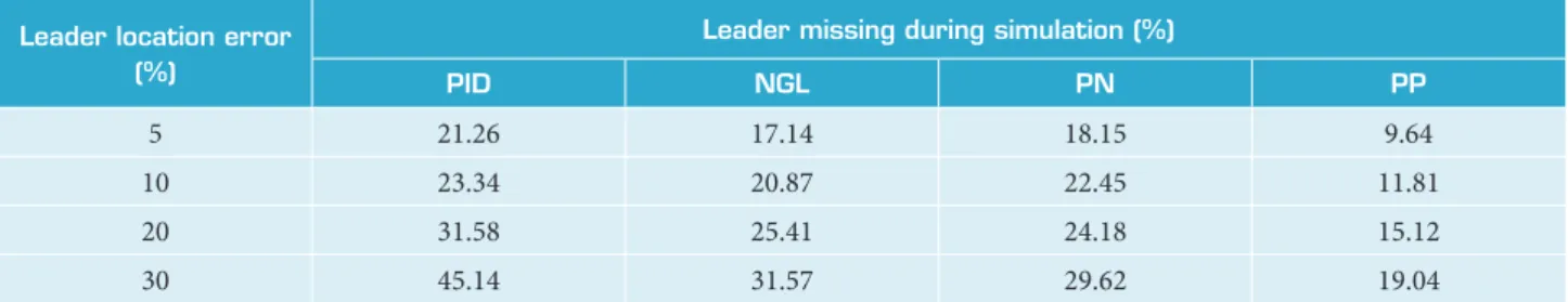
Table 3. Leader missing due to leader location error.
Leader location error (%)
Leader missing during simulation (%)
PID NGL PN PP
5 21.26 17.14 18.15 9.64
10 23.34 20.87 22.45 11.81
20 31.58 25.41 24.18 15.12
30 45.14 31.57 29.62 19.04
in the noise-free modes, NGL and model-based methods are more efficient than other methods such PN and PP. PN and PP methods are more efficient than the other methods for tolerating the errors where the input errors size increases. According to simulations, the sensitivity results show the performance of PN and PP methods, but PP has the least leader missing factor in the noisy situations. So this method is suitable for other simulations.
MANEUVER RESULTS
In this article, a six-degrees-of-freedom Aerosonde UAV model is used for coordinated maneuver. A nonlinear Simulink model of Aerosonde was derived based on that provided in the Unmanned Dynamics AeroSim Blockset (Unmanned Dynamics LLC 2016). Nonlinear six-degrees-of-freedom model is applied to simulate the control processes for formation flight and different
A Hierarchical and Prioritized Framework in Coordinated Maneuver of Multiple UAVs Based on Guidance Regulator
xx/xx
maneuvers. This model considers all the possible environmental factors and uncertainties including wind, wind shear, and atmospheric turbulence by using the total atmospheric model in its control program.
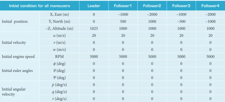
In order to evaluate the efficiency of the designed algorithms for performing maneuvers, some linear and nonlinear maneuvers were tested. For simulating the critical condition, UAV’s starting point for all the maneuvers is set at different positions and different altitudes. The maneuver paths for the leader UAV are planned at several specific trajectories. The second-row UAVs at both sides of the leader must follow the virtual leader, according to the guidance and control algorithm at reference distance behind the leader. For the case of an unlimited number of airplanes, the virtual leader for a follower at each row is only formed within the reference distance from the direct frontal UAV. Equations of UAV’s guidance and control (Eqs. 12 to 23) are implemented in all followers. Table 4 denotes the initial condition for leader and followers in all maneuvers.
Table 4. Leader and followers initial condition for all maneuvers.
Initial condition for all maneuvers Leader Follower1 Follower2 Follower3 Follower4
Initial position
X, East (m) 0 –1000 –2000 –1000 –2000
Y, North (m) 0 500 1000 –500 –1000
–Z, Altitude (m) 1025 1000 1000 1000 1000
Initial velocity
u (m/s) 20 20 20 20 20
v (m/s) 0 0 0 0 0
w (m/s) 0 0 0 0 0
Initial engine speed RPM 5000 5000 5000 5000 5000
Initial euler angles
ϕ (deg) 0 0 0 0 0
θ (deg) 0 0 0 0 0
Ψ (deg) 0 0 0 0 0
Initial angular velocity
p (deg/s) 0 0 0 0 0
q (deg/s) 0 0 0 0 0
r (deg/s) 0 0 0 0 0
Linear Maneuvers
For analysis of linear motion, three maneuvers are considered as follows. In these types of maneuver, the leader UAV has a straight longitudinal velocity equal to 20 m/s in three different directions far from followers. As shown in Figs. 9 to 11 each UAV
1040
Follower #1 Virtual leader
Virtual leader #1
Follower #2 Virtual leader #2
Follower #3 Virtual leader #3
Follower #4 Virtual leader #4 Leader
U
p (m)
1060
1020
1000 1000
East (m) ×104
980 1500
1.5 2.5 2
1 0.5
J. Aerosp. Technol. Manag., São José dos Campos, v11, e1119, 2019 Haghighi H; Sadati SH; Karimi J; Dehghan MM xx/xx
Figure 10. Straight maneuver in East direction with altitude increase.
-500 1400
500
Follower #1 Virtual leader
Virtual leader #1
Follower #2 Virtual leader #2
Follower #3 Virtual leader #3
Follower #4 Virtual leader #4 Leader
U
p (m)
-1000 -1500 0
1600
1200
1000 1000
North (m)
East (m) ×104 800
1500
1.5
2.5 2 1
0.5 0 -0.5
-1 1040
1 1030
Follower #1 Virtual leader
Virtual leader #1
Follower #2 Virtual leader #2
Follower #3 Virtual leader #3
Follower #4 Virtual leader #4 Leader
U
p (m)
-1000 0
1060
1020
2 1000
North (m) East (m)
×104
990 1050
2000 1000
-2000
0 1010
Figure 11. Straight maneuver in North direction without altitude change.
starts its motion from the different starting point and tries to approach the virtual leading point defined based on the distance from the frontal UAV. The obtained results demonstrate the high accuracy achieved by using a hierarchical method of performing the maneuver.
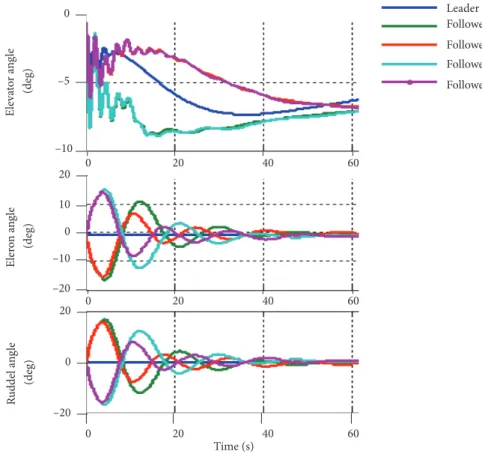
To evaluate the controlling sensitivity, state-change controller and coordinated flight, results belonging to the first 100 s of sample maneuver as a most critical phase of motion are shown in Fig. 12.
In Fig. 12 the surface deflection of UAVs is compared to the motion beginning. These results show that the guidance-control platform played a good role in damping the uncertainty as well as coordinating deflection due to coordinated maneuvers. UAVs on the same side have the same deflection approach and contrast those on the opposite side.
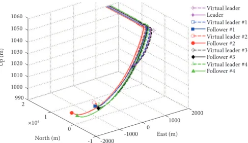
Nonlinear Maneuver
For nonlinear analysis, two types of nonlinear circular maneuvers are considered: steady-state level turn, and helical turn. The steady state level turn maneuver is performed in a circular motion with a radius of about 4 km and zero rate of climb at a constant speed for the leader UAV. In helical maneuver, a circular path is defined with a radius of about 4 km and rate of climb equal to
A Hierarchical and Prioritized Framework in Coordinated Maneuver of Multiple UAVs Based on Guidance Regulator
xx/xx
Leader Follower 1 Follower 2 Follower 3 Follower 4 0
E
le
va
to
r a
n
gle
(deg) –5
–10
20
E
ler
o
n a
n
gle
(deg)
10
0
–10
–20 20
R
udde
l a
n
gle
(deg)
0
–20
0 20 40 60
Time (s)
0 20 40 60
0 20 40 60
1040
5000
-2000
Follower #1 Virtual leader
Virtual leader #1
Follower #2 Virtual leader #2
Follower #3 Virtual leader #3
Follower #4 Virtual leader #4 Leader
U
p (m)
1010 1030
0 1060
1020
2000 1000
North (m) 990 1050
4000 0
Figure 12. Leader and followers control surface deflection.
J. Aerosp. Technol. Manag., São José dos Campos, v11, e1119, 2019 Haghighi H; Sadati SH; Karimi J; Dehghan MM xx/xx
Figure 14. Maneuver motion in a spiral path.
the airplanes and a closed position to the leader UAV at the starting point. Figures 13 and 14 show that, although this maneuver started under difficult and unusual initial conditions, great robustness is observed from the proposed algorithm.
Table 5 shows the collision probability for 100 simulations of each maneuver in a variety of initial conditions. These results show that the priority basis method has the lesser collision probability and causes the safer coordinated tracking.
Table 5. Collision probability in different maneuvers according to priority.
Maneuver type
Collision probability during 100 simulations (%) Priority bases Without priority
Steady-state cruise 1.31 9.73
Climb 3.63 15.41
Turn 4.22 19.10
Helical 5.94 21.84
CONCLUSIONS AND FUTURE DIRECTIONS
This paper presented an approach to the design of hierarchical trajectory tracking which sustains specified geometry in multiple UAV maneuvers. The objective of this paper is the development of a general framework to implement several formation maneuvers due to UAVs relative distance, attitude and mission requirements. It contributes decentralized method to gathering all of the UAVs during leader path following. Each UAV tracks the trajectory of its own virtual leader created by the frontal UAV.
We use the guidance-based control in this paper. The main advantage is independent execution instead of other model-based approaches such as inertial angle control or nonlinear control. The model-model-based approaches are usually associated with vehicles dynamics model and are sensitive to the disturbances. Also, the advantage of the proposed method is associated with a tracking where the nose is always pointing to the leader and the target will not be missed. This makes a precise tracking with less equipment. In the result section, we compare the results from this work and other approaches.
The design is based on compensation-type controllers to minimize tracking errors along the forward, lateral and vertical axes. The analysis shows that the availability of the Euler angles from the leader aircraft is critical for the wingman to maintain the assigned formation geometry throughout the maneuvered flight. The design has been verified through a set of simulation
1200
0 1000
Follower #1 Virtual leader
Virtual leader #1
Follower #2 Virtual leader #2
Follower #3 Virtual leader #3
Follower #4 Virtual leader #4 Leader
U
p (m)
1600
5000
–5000
North (m) East (m)
1400
5000
-5000
0 800
A Hierarchical and Prioritized Framework in Coordinated Maneuver of Multiple UAVs Based on Guidance Regulator
xx/xx
studies interfacing the aircraft models and the guidance-control schemes in Simulink with a real environment. The results of the simulation show a desirable performance of the formation control in maneuvering schemes.
In the control algorithm, all the gains amplitude are computed by Ziegler-Nichols (1942) method in the linear form of the equation of motion; but due to great uncertainty used in Aerosonde model, all the gains were tuning manually before the maneuver. With several try and error (TAE) methods, the constant gains are regulated around the Ziegler-Nichols magnitude until satisfying all types of maneuver. In the case of sensitivity, the guidance-based methods have higher robustness and better response to error increasing. The results of NGL, PN and PP are almost in the same range but PN and PP are more robust against the error increasing. The PP method has the least leader missing in maneuver situation so this can be a more appropriate structure for this problem.
Although good responses are achieved from designed guidance and control system, some limitations are neglected. Communication range between UAVs, camera resolution, FOV limitation, and time delay of camera object recognition have to assign to equations. Future works can focus on designing guidance law and control scheme due to communication and camera limitations. Another approach to future works is to derive relative parameters from another sensor such as infrared and ultrasonic to perform camera data fusion due to camera uncertainty. For PID gains in the nonlinear platform, we suggest some gain scheduling methods such as fuzzy PID and Neuro-fuzzy method, using the variable coefficients instead of constant coefficients to increase controller performance. There is a considerable trade-off between coordinated flight and guidance method at the beginning of formation maneuvers when UAVs start a formation from different initial points. All guidance commands try to solve a minimum time problem while coordinated commands make a different situation. The transient patterns can be introduced as another future work related to fuzzy or optimal control as well as heuristic methods.
AUTHOR’S CONTRIBUTION
Conceptualization, H Haghighi, MM Dehghan; Methodology, SH Sadati; Investigation, SH Sadati, J Karimi, MM Dehghan; Writing – Original Draft, H Haghighi; Writing – Review and Editing, SH Sadati, J Karimi; Resources, SH Sadati, MM Dehghan; Supervision, SH Sadati.
Ali SU, Samar R, Shah MZ, Bhatti AI, Munawar K, Al-Sggaf, UM (2016) Lateral guidance and control of UAVs using second-order sliding modes. Aerospace Science and Technology 49:88-100. https://doi.org/10.1016/j.ast.2015.11.033
Blakelock JH (1991) Automatic control of aircraft and missiles. 2nd ed. Hoboken: John Wiley & Sons.
Unmanned Dynamics LLC (2016) Dynamic model of aerosonde UAV. Unmanned Dynamics LLC; [accessed 2016 Sep 03]. http://www.u-dynamics.com/aerosim/
Frazzoli E (2002) Maneuver-based motion planning and coordination for multiple UAVs. Presented at: 21st Digital Avionics Systems Conference; Irvine, USA. https://doi.org/10.1109/DASC.2002.1052947
Gavilan F, Vazquez R, Camacho EF (2015) An iterative model predictive control algorithm for UAV guidance. IEEE Transactions on Aerospace and Electronic Systems 51(3):2406-2419. https://doi.org/10.1109/TAES.2015.140153
Kumaresan G, Singh GK (2016) Decentralized formation flying using modified pursuit guidance control laws. Presented at: Indian Control Conference (ICC); Hyderabad, India. https://doi.org/10.1109/INDIANCC.2016.7441157
Liu W, Zheng Z, Cai K (2013) Adaptive path planning for unmanned aerial vehicles based on bi-level programming and variable planning time interval. Chinese Journal of Aeronautics 26(3):646-660. https://doi.org/10.1016/j.cja.2013.04.041
Min BM, Tahk MJ (2005) Three-dimensional Guidance Law for Formation Flight of UAV. ICCAS 2005(6):463-467.
Oh KK, Park MC, Ahn HS (2015) A survey of multi-agent formation control. Automatica 53:424-440. https://doi.org/10.1016/j.
REFERENCES
J. Aerosp. Technol. Manag., São José dos Campos, v11, e1119, 2019 Haghighi H; Sadati SH; Karimi J; Dehghan MM xx/xx
Sadeghi M, Abaspour A, Sadati SH (2015) A novel integrated guidance and control system design in formation flight. Journal of Aerospace Technology and Management 7(4):432-442. https://doi.org/10.5028/jatm.v7i4.473
Shah MZ, Samar R, Bhatti AI (2015) Guidance of air vehicles: a sliding mode approach. IEEE Transactions on Control Systems Technology 23(1):231-244. https://doi.org/10.1109/TCST.2014.2322773
Stengel RF (1993) Toward intelligent flight control. IEEE Transactions on Systems, Man, and Cybernetics 23(6):1699-1717. https://doi. org/10.1109/21.257764
Wang Y, Wang D (2017) Tight formation control of multiple unmanned aerial vehicles through an adaptive control method. Science China Information Sciences 60:070207. https://doi.org/10.1007/s11432-016-9092-y
Xue R, Cai G (2016) Formation flight control of multi-UAV system with communication constraints. Journal of Aerospace Technology and Management 8(2):203-210. https://doi.org/10.5028/jatm.v8i2.608
Yamasaki T, Takano H, Baba Y (2009) Robust path-following for UAV using pure pursuit guidance. In: Lam TM, editor. Aerial Vehicles. Shanghai: IntechOpen. p. 671-690. https://doi.org/10.5772/6494
Yang E, Masuko Y, Mita T (2004) Dual controller approach to three-dimensional autonomous formation control. Journal of guidance, control, and dynamics 27(3):336-346. https://doi.org/10.2514/1.1562
Zhang Q, Liu HH (2017) Aerodynamics modeling and analysis of close formation flight. Journal of Aircraft 54(6):2192-2204. https:// doi.org/10.2514/1.C034271
Zhao J, Zhou R (2016) Obstacle avoidance for multi-missile network via distributed coordination algorithm. Chinese Journal of Aeronautics 29(2):441-447. https://doi.org/10.1016/j.cja.2016.01.011