Departamento de Engenharia Electrot´ecnica
An Agent-Based Evolutionary Approach
For Manufacturing System Layout Design
Por
Nuno Emanuel Nunes Pereira
Dissertac¸˜ao apresentada na Faculdade de Ciˆencias e Tecnologia da Universidade Nova de Lisboa para obtenc¸˜ao do grau de Mestre em Engenharia Electrot´ecnica e de Computadores
Orientador: Doutor Jos´e Ant´onio Barata de Oliveira
J´uri:
Presidente: Doutor Pedro Alexandre da Costa Sousa Vogal: Doutor Jos´e Ant´onio Barata de Oliveira Vogal: Doutor Jo˜ao Paulo Branquinho Piment˜ao
An Agent-Based Evolutionary Approach For Manufacturing System Layout Design
Copyright cTodos os direitos reservados a Nuno Pereira, FCT/UNL e UNL
A Faculdade de Ciˆencias e Tecnologia e a Universidade Nova de Lisboa tˆem o direito, perp´etuo e sem limites geogr´aficos, de arquivar e publicar esta dissertac¸˜ao atrav´es de exemplares impressos reproduzi-dos em papel ou de forma digital, ou por qualquer outro meio conhecido ou que venha a ser inventado, e de a divulgar atrav´es de reposit´orios cientificos e de admitir a sua c´opia e distnibuic¸˜ao com objectivos educacionais ou de investigac¸˜ao, n˜ao comerciais, desde que seja dado cr´edito ao autor e editor.
Para a minha Fam´ılia
E os meus Amigos
Acknowledgments
Many people contributed in one way or another to me reaching this point of my life and to the conclusion of this work. They loved me, cared for me and supported me through my life as a student and, more importantly, through my life as a person.
These people are: my mother and father, my grandmother, my brother Bruno Pereira, my cousins Patr´ıcia Nunes and Gonc¸alo Mateus, my aunts and uncles, Marijke Niessen, Gonc¸alo Costa, Jos´e Belo, Jos´e Luzio, Hugo Lopes, Francisco Ganh˜ao, the ”hard core” of the Mestrado Integrado em Engenharia Electrot´ecnica, and my colleagues and friends outside the university. To all of you, my most sincere thanks.
I want to thank Professor Jos´e Barata for the opportunity to develop the work presented in this thesis. I also thank Dr. Regina Frei for her ideas.
Resumo
Nesta tese ´e apresentada uma soluc¸˜ao para o problema do desenho dolayoutde um sistema de manufac-tura, uma parte importante da sua fase de projecto, dada a influˆencia que tem na eficiˆencia do sistema e, portanto, na sua capacidade de produc¸˜ao e de lidar com falhas.
A soluc¸˜ao apresentada tem por base um algoritmo gen´etico que, utilizando a informac¸˜ao que ´e fornecida pelo utilizador atrav´es de um ficheiro de ontologia, e utilizando algoritmos da teoria de grafos, desenha olayoutdo sistema de manufactura. As instˆancias da ontologia representam recursos de manu-factura e suas caracter´ısticas que, quando utilizados pelo algoritmo, s˜ao codificados em cromossomas e nos seus genes.
O algoritmo inicia-se com um n´umero de cromossomas comfitnessbaixa que, com a evoluc¸˜ao di-reccionada proporcionada pelo algoritmo, que ´e condicionada por parˆametros de controlo que podem ser alterados pelo utilizador, melhoram com o surgimento de novas gerac¸˜aes. Considera-se que a mel-hor soluc¸˜ao ´e aquela que conecta, por ordem, todos os recursos necess´arios para realizar as operac¸˜oes requeridas pelo plano de manufactura descrito na ontologia, sem que estes se sobreponham quando o layout ´e constru´ıdo.
A configurac¸˜ao apresentada pelo sistema de transporte de partes e materiais, nolayout escolhido, est´a apenas dependente dos recursos dispon´ıveis e da func¸˜ao defitnessutilizada pelo algoritmo gen´etico, sendo que esta ´ultima n˜ao pode ser alterada pelo utilizador. Esta soluc¸˜ao diferencia-se das demais por posicionar simultaneamente todos os componentes do sistema de manufactura e n˜ao apenas estac¸˜oes de trabalho ou o sistema de transporte.
A soluc¸˜ao ´e direccionada paraevolvable assembly systems, pelo que foi implementada dentro de um agente, para poder ser integrada num sistema multiagente, a ser utilizado para controlar um sistema de manufactura, com um m´ınimo de alterac¸˜oes.
Palavras-chave: desenho de layout, sistema de manufactura, sistema multiagente, ontologia, algo-ritmo gen´etico.
Abstract
In this thesis it is presented an approach to the problem of layout design for a manufacturing system, which is an important part of its design stage, given that it has influence in the system efficiency and, therefore, in its output rate and fault handling capabilities.
The presented approach is based on a Genetic Algorithm (GA) that, by using information provided by the the user through an ontology file, and by using algorithms from graph-theory, designs the layout of a manufacturing system. The instances of the ontology represent manufacturing resources and their characteristics that, when they are being used by the algorithm, are encoded in chromosomes and in their genes.
The algorithm begins with a number of chromosomes with low fitness which, with the directed evolution provided by the algorithm, that is restricted by the control parameters that might be tunned by the user, improve with the passing of the new generations. It is considered that the fittest solution is the one that connects, in order, all the resources required by the manufacturing plan, described in the ontology, without the occurrence of overlaps when the layout is constructed.
The configuration presented by the transport system that handles parts and materials, in the selected layout, is only dependent on the available resources and on the fitness function used by the GA, being that the last cannot be changed by the user. This approach differs from others by positioning simultaneously all the components of the manufacturing system and not only workstations or transport system.
The solution is directed to evolvable assembly systems, purpose for which it was implemented inside an agent, so it can be integrated in a Multiagent System (MAS) to be used in the control of a manufac-turing system with minimal changes.
Keywords: layout design, manufacturing system, multiagent system, ontology, genetic algorithm.
Contents
Acknowledgments vii
Resumo ix
Abstract xi
Acronyms xix
1 Introduction 1
1.1 Context . . . 1
1.2 Problem . . . 1
1.3 Hypothesis . . . 2
1.4 Objectives And Contributions . . . 2
1.5 Structure of the Dissertation . . . 2
2 State Of The Art, Related Work And Supporting Concepts 5 2.1 Manufacturing Paradigms . . . 5
2.1.1 Flexible Manufacturing Systems . . . 6
2.1.2 Intelligent Supervising Systems . . . 6
2.1.3 Agility in Manufacturing Systems . . . 8
2.1.4 Evolvable Assembly Systems . . . 8
2.1.5 Self-Organisation in Manufacturing Systems . . . 10
2.2 Control Approaches . . . 12
2.2.1 Centralised . . . 12
2.2.2 Hierarchical . . . 12
2.2.3 Modified Hierarchical . . . 13
2.2.4 Heterarchical . . . 13
2.3 Agent-Based Control . . . 14
2.3.1 Individual Agent . . . 14
2.3.2 Agent Typologies . . . 15
2.3.3 Multiagent Systems . . . 17
2.3.4 Communication Technologies . . . 18
2.3.5 Integrating Agents In Custom Applications: The Jade Framework . . . 18
2.4 Ontologies . . . 19
2.4.1 Language Specifications: RDF and OWL . . . 19
2.4.2 Editing Tools: Prot´eg´e . . . 20
2.4.3 Integrating Ontologies In Custom Applications: Jena Java API . . . 20
2.4.4 Manufacturing Ontologies: EUPASS Ontology . . . 20
2.5 Genetic Algorithms . . . 21
2.5.1 Encoding Information . . . 21
2.5.2 Selection Of Parents . . . 22
2.5.3 Crossover Operator . . . 22
2.5.4 Mutation Operator . . . 23
2.5.5 Fitness Evaluation . . . 23
2.5.6 Integrating Genetic Algorithms In Custom Applications: JGAP . . . 23
2.6 Manufacturing System Design . . . 23
2.6.1 Equipment Selection . . . 24
2.6.2 Equipment Layout . . . 24
2.6.3 Layout Configurations . . . 25
2.6.4 Layout Design With Genetic Algorithms . . . 27
2.7 Graphs . . . 27
2.7.1 Integrating Graphs In Custom Applications: JGraphT . . . 28
3 System Architecture 31 3.1 Control Approach . . . 31
3.1.1 Design Time . . . 31
3.1.2 Run-Time . . . 32
3.2 Types of Agents . . . 33
3.2.1 Resource Agent . . . 33
3.2.2 Layout Agent . . . 33
3.2.3 System Agent . . . 33
3.2.4 Directory Facilitator Agent . . . 34
3.3 Agent Knowledge . . . 34
3.3.1 Manufacturing Plan . . . 34
3.3.2 Resource Description . . . 35
3.4 Agent Behaviours . . . 35
3.4.1 Registrations In DF . . . 36
3.4.2 Information Requests To DF . . . 36
3.4.3 Layout Design . . . 36
3.4.4 Coalition Creation . . . 37
3.4.5 Workflow Execution . . . 37
3.4.6 Coalition Coordination . . . 37
4 Supporting Ontologies 39 4.1 Product Manufacturing Plan . . . 39
4.2 Resources . . . 39
5 Genetic Algorithm For Layout Design 41 5.1 Chromosome . . . 41
5.2 Selection Of Parents . . . 41
5.3 Crossover Operator . . . 41
5.4 Mutation Operator . . . 42
5.5 Fitness Evaluation . . . 43
6 Implementation 47 6.1 Programming In Java . . . 47
6.2 NetBeans . . . 47
6.3 The Layout Agent . . . 48
6.3.1 Constructor . . . 48
6.3.2 Setup . . . 48
6.3.3 Events . . . 48
6.4 Graphical User Interface Of The Layout Agent . . . 49
6.4.1 Control Parameters . . . 49
6.4.2 Starting Layout Design . . . 49
6.4.3 Consulting Other Solutions . . . 49
6.5 Layout Behaviour . . . 50
6.5.1 Constructor . . . 50
6.5.2 Action . . . 50
6.5.3 Done Method . . . 50
6.6 Ontology Integration . . . 51
6.6.1 Model Setup . . . 51
6.6.2 Retrieving Connection Points . . . 51
6.6.3 Retrieving Required Resources . . . 51
6.6.4 Retrieving Resource Dimensions . . . 52
6.6.5 Retrieving Connection Point Data . . . 52
6.7 Configuration . . . 52
6.8 Encoding Chromosomes And Genes . . . 53
6.8.1 Chromosomes . . . 53
6.8.2 Composite Genes . . . 53
6.8.3 Genes . . . 54
6.9 Crossover And Mutation Operators . . . 55
6.10 Fitness Evaluation . . . 55
6.10.1 Constructor . . . 55
6.10.2 Fitness Function . . . 55
6.11 Graph Methods . . . 56
6.11.1 Creating A Graph From A Chromosome . . . 56
6.11.2 Creating A Layout From A Graph . . . 56
6.11.3 Determination Of The Source And Target Connection Points In A Resource Con-nection Edge . . . 57
6.12 Transform Methods . . . 57
6.12.1 Rotation . . . 57
6.12.2 Translation . . . 57
6.12.3 Inversion . . . 57
6.12.4 Rectangular Area And Areas Of Any Shape . . . 58
6.13 Decoding . . . 58
7 Validation And Test Cases 59 7.1 Test 4R3P1T . . . 59
7.2 Test 6R4P2T . . . 60
7.3 Test 5R3P1T . . . 60
7.4 Test 9R3P2T . . . 61
8 Conclusions 65 8.1 Future Work . . . 67
Bibliography 69
List of Figures
2.1 Information flow in a supervising architecture . . . 7
2.2 An evolvable assembly system architecture . . . 10
2.3 Interactions in a centralised control architecture . . . 13
2.4 Interactions in a hierarchical control architecture . . . 14
2.5 Interactions in a modified hierarchical control architecture . . . 15
2.6 Interactions in a heterarchical control architecture . . . 16
2.7 A genetic algorithm evolution cycle . . . 21
2.8 The structure of a chromosome . . . 22
2.9 Single point crossover effect . . . 22
2.10 Mutation effect . . . 23
2.11 Transfer line layouts . . . 29
2.12 Centralised layout . . . 30
2.13 Functional layout . . . 30
2.14 Distributed layout . . . 30
3.1 Information flow at the beginning of design time . . . 32
3.2 Information flow at the end of design time . . . 32
3.3 Control approach at run-time . . . 33
3.4 A manufacturing plan structure . . . 34
3.5 Connection points of resources . . . 35
5.1 Information encoding in a chromosome . . . 42
5.2 Connection points of a conveyor belt . . . 43
5.3 Crossover in the layout algorithm . . . 44
5.4 Mutation in the layout algorithm . . . 44
5.5 A path in a layout . . . 45
6.1 Graphical user interface of the layout agent . . . 49
7.1 Solution presented by the layout algorithm for the test 4R3P1T . . . 60
7.2 Sequence of solutions presented by the layout algorithm for the test 6R4P2T . . . 62
7.3 Sequence of solutions presented by the layout algorithm for the test 5R3P1T . . . 63
7.4 Solution presented by the layout algorithm for the test 9R3P2T . . . 64
Acronyms
ACL Agent Communication Language
AEI Advanced Enabling Interface
API Application Programming Interface
AGV Automated Guided Vehicle
BDI Belief-Desire-Intention
CoBASA Coalition Based Approach For Shop Floor Agility
DF Directory Facilitator
EAS Evolvable Assembly System
EUPASS Evolvable Ultra-Precision Assembly Systems
FAS Flexible Assembly System
FIPA Foundation For Intelligent Physical Agents
FMS Flexible Manufacturing System
GA Genetic Algorithm
GUI Graphical User Interface
ICT Information And Communication Technology
IDE Integrated Development Environment
JADE Java Agent Development Framework
Jena Jena Semantic Web Framework For Java
JGAP Java Genetic Algorithms Package
KIF Knowledge Interchange Format
KQML Knowledge Query Manipulation Language
MAS Multiagent System
MGA Messy Genetic Algorithm
NetBeans Netbeans Integrated Development Environment
OS Operating System
OWL Web Ontology Language
Pellet Pellet OWL-DL Reasoner
R&D Research And Development
RDF Resource Description Framework
SA Self-Adaptive
SO Self-Organising
SOA Service-Oriented Architecture
SPARQL SPARQL Query Language For RDF
SWRL Semantic Web Rule Language
URI Uniform Resource Identifier
W3C World Wide Web Consortium
Chapter 1
Introduction
The first humans to inhabit planet Earth were fully dependent on Nature to survive. They would collect from Nature everything they required, not only food and water, but also animal skins and bones, wood and stone which were used to manufacture clothes, shelter and tools [Nunes et al., 1995]. Those times are past but the need to transform what Nature gives in order to satisfy the necessities of society still remains. There are differences though. Nowadays, with the growing understanding of the universe, mankind relies on artificial machines to execute the most difficult, repetitive and precision requiring tasks, which can be witnessed in different domains such as search and rescue, medicine, warfare, space exploration, construction and manufacturing [Frei et al., 2009b].
1.1
Context
The purpose of a manufacturing company is to manufacture a product that will enter the market where it will be available for consumers to buy. Consumers will only purchase what they need, like and can afford. In this way, they have great influence in the manufacturing world. Furthermore, unless a company has the monopoly1of the market, competing companies are always a concern, since they will try to make their products more appealing to consumers then those of other companies. For both these reasons, a manufacturing company has to manufacture products that are attractive to consumers in terms of quality and cost, and that often have to be improved or renewed given their short life-cycle.
1.2
Problem
Companies have to be able to cope with the market demands described in Section 1.1 while maintaining the manufacturing costs of their products as low as possible. Tompkins et al. [2010] stated that between 20 and 50% of the total operating expenses within manufacturing is attributed to material handling. The
1A monopoly is an exclusive ownership through legal privilege, command of supply, or concerted action [’monopoly’, 2010]
2 CHAPTER 1. INTRODUCTION
efficiency of a material handling system is dependent on the layout of the whole manufacturing system, which is difficult to design and costly to modify [Rajasekharan et al., 1998]. The problem of generating the best layout for a manufacturing system is very old and, due to the complexity of designing a system flexible to handle a variety of product requirements and agile to handle the introduction of new products, research efforts have only produced a number of incomplete solutions.
1.3
Hypothesis
A manufacturing system capable of self-organising provides a way of addressing the problem described in Section 1.2 by automating part of the layout design process. The following hypothesis are formu-lated: a manufacturing system is capable of designing its layout using self-organisation if it has access to enough information about itself and the world around it. It is possible to define and implement an archi-tecture able to create its own layout. The resulting implementation facilitates the the task of designing a manufacturing system’s layout.
1.4
Objectives And Contributions
The objective and contribution of this thesis is to design and implement an agent architecture compliant with the hypothesis of Section 1.3. This architecture is capable of designing the layout of a manufacturing system by integrating agent technology, ontologies, genetic algorithms and graph-theory algorithms.
1.5
Structure of the Dissertation
The dissertation is structured in eight chapters:
• Chapter 2 - state of the art of manufacturing technology and related work: manufacturing paradigms, control approaches, agent-based control, ontologies, genetic algorithms, layout design, and graph-theory algorithms.
• Chapter 3 - agent’s architecture and integration of modules: ontologies, genetic algorithms and graph-theory algorithms.
• Chapter 4 - support ontology that describes the manufacturing plan and manufacturing resources.
• Chapter 5 - genetic algorithm: coding of the chromosomes, mutation operators and fitness func-tions.
1.5. STRUCTURE OF THE DISSERTATION 3
• Chapter 7 - tests performed to validate the implementation.
Chapter 2
State Of The Art, Related Work And
Supporting Concepts
A manufacturing company integrates product development and design activities with the process of pro-ducing the product and with business, which involves distribution, marketing and service infrastructure [Leit˜ao, 2004]. The work developed in this thesis focuses mainly in the product description and corre-sponding manufacturing system.
2.1
Manufacturing Paradigms
A manufacturing system is a combination of machines, tools and human workers organised in worksta-tions and interconnected by transporters and material handling technology. The manufacturing process results of the coordinated action of humans and manufacturing equipment and is defined by Groover [2007]:
”Manufacturing can be defined as the application of physical and chemical processes to alter the geometry, properties, and/or appearance of a given starting material to make parts or products; manufacturing also includes the joining of multiple parts to make assembled products.”
This means that product, process and system are intrinsically related to one another. Hence, a change in product design may have an impact on the process and the system. Likewise, a change in a process may imply a change in the product design and system [Frei et al., 2009b]. Nonetheless, a manufacturing system should be able to respond instantaneously to product demands [Davidow and Malone, 1993]. However, the readiness and quality of that response is dependent on the control architecture and physical layout of the system. Although the majority of manufacturing companies remains resilient to the replace-ment of their antiquated but well known manufacturing system of many years by a strange and complex
6 CHAPTER 2. STATE OF THE ART, RELATED WORK AND SUPPORTING CONCEPTS
system that just came out of Research And Development (R&D), manufacturing paradigms have been evolving through the years and the ones available today allow the design of flexible and agile systems that are able to deal with product diversity, change and uncertainty.
2.1.1 Flexible Manufacturing Systems
Flexibility is the capability to adapt to new, different, or changing requirements [’flexibility’, 2010]. A manufacturing system gains this capability when it is designed to handle predictable variations. Leit˜ao [2004] identifies different types of flexibility, such as mix, changeover, volume, product and sequencing. Each type is characterized by dealing with a different variation:
• mix flexibility - the capability to deal with a range of products or variants;
• changeover flexibility - the capability to quickly change the manufacturing system to offer a new product;
• volume flexibility - the capability to deal with demands of variable volume;
• product flexibility - the capability to quickly modify a product design;
• sequencing flexibility - the capability to support different sequences of the operations that are part of the manufacturing plan.
The control of a Flexible Manufacturing System (FMS) is carried out by an integrated computational system [Upton, 1992] and its main limitation is its inflexibility to the introduction of new products due to the complexity of automatically making the required adjustments [Leit˜ao, 2004].
2.1.2 Intelligent Supervising Systems
Intelligent Supervising Systems are an approach to FMS [Camarinha-Matos et al., 1996]. They include a planning module which is responsible for the generation of executable manufacturing plans. However, the generated plan is based on a simplified model of the world, which does not consider every hypothesis and, even if it did, there can be the occurrence of unpredictable events. Therefore, there is the need for a supervising module, which is responsible for executing the plan and generating eventual recovery plans. The supervising module is composed of:
• dispatcher - Executes the manufacturing plan, given by the planning module, by sending execution commands to the device controllers.
2.1. MANUFACTURING PARADIGMS 7
• diagnosis - Analyses the issues encountered and identifies their origin.
• recovery - Tries to recover from the issue by generating a recovery manufacturing plan.
Figure 2.1 shows the information flow between these modules in a possible supervising architecture.
S u p e rv is in g m o d u le Planning module
Dispatcher Monitoring Diagnosis Recovery
Actuators and sensors
Figure 2.1: Information flow in a supervising architecture
Supervising applications may include extra functionalities:
• prognosis - Analyses the temporal evolution of a set of state variables and tries to anticipate the occurrence of errors.
• preventive maintenance - Similarly to recovery, this functionality generates preventive mainte-nance plans.
• learning - Improves the performance of the previous functionalities through the acquisition of knowledge.
Supervising systems are applied when a real-time system is required to handle different asynchronous events in a certain time limit. If expert techniques from the artificial intelligence domain are used in the implementation of a real-time system, a real-time expert system is obtained.
Expert Systems
8 CHAPTER 2. STATE OF THE ART, RELATED WORK AND SUPPORTING CONCEPTS
2.1.3 Agility in Manufacturing Systems
Agility is the ability to thrive and prosper in an environment of constant and unpredictable change [Gold-man et al., 1995] and it covers different areas of [Gold-manufacturing, from [Gold-management to shop floor [Barata, 2005]. A manufacturing system that has this ability is able to deal with change and uncertainty [Barata, 2005] and with things that cannot be controlled [Maskell, 2001]. Barata [2005] includes a list of re-quirements for a successful implementation of agile manufacturing, from which the following points are relevant in the context of this thesis:
• information technology - Information And Communication Technologies (ICTs) are required to provide the computational support needed for the creation of an agile shop floor.
• new agile shop floor strategies - Actors, processes and areas involved in the manufacturing system should be studied for the development of a methodology that helps the integration of these elements during the creation of an agile shop floor to support their life cycle evolution.
2.1.4 Evolvable Assembly Systems
Evolvable Assembly Systems (EASs) arose as a solution to the problem of achieving agility in assembly systems. They are based on the concept of emergence whose basic idea is that complex systems exhibit expected and unexpected properties and behaviours resulting from the integration of components with known and unknown characteristics. Their composition consists of several reconfigurable, task-specific and process oriented modules which allows for a continuous evolution together with the product and the corresponding assembly process. These characteristics allow modules to live beyond the product life cycle [Frei et al., 2009a, Barata and Onori, 2006, Onori et al., 2005].
Barata and Onori [2006] list some requirements to successfully designing an EAS:
• module - Any unit that can perform operations and integrates a specific interface.
• granularity - The lowest level of device being considered in the reference architecture. The lower the level of the building blocks the higher the emergent behaviour.
• plugability - The ability to rearrange and integrate system components within the framework of a given system architecture. A legacy system1 can be adapted into an EAS component through an Advanced Enabling Interface (AEI) that enables the communication with other EAS components.
• reconfigurability (interoperability) - The ability to rearrange available system components to per-form new, but predefined functions.
2.1. MANUFACTURING PARADIGMS 9
• evolvability - The reconfiguration of the system platform enables new or refined levels of func-tionality.
The architecture of an EAS is composed of an individual module architecture and a global system archi-tecture.
Individual Module
An individual physical module is represented by a computational model that must be part of the archi-tecture. This model must possess a set of attributes that capture the relevant physical characteristics of the module and are to be used for its operation, configuration and selection. Model functionalities should capture the behaviour of the physical module and realize the necessary control actions that must be is-sued for the behaviour to be accomplished [Onori et al., 2005]. They are offered as skills and each skill represents the capability of the module to perform a certain task, which may be dependent on some or all the represented attributes. A skill execution may involve performing a sequence of the control actions offered by the module controller. A control action should be offered in a skill execution sequence, and not alone, when its resulting effect is not significantly relevant to the assembly process.
Assembly System
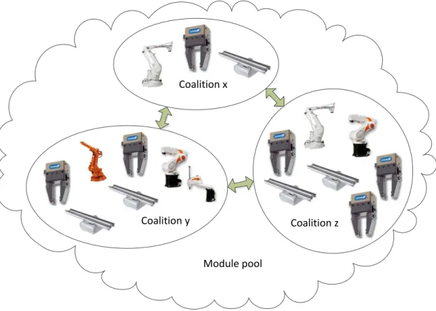
The global architecture of the assembly system should support easy addition and removal of modules and also support their interactions, such as synchronization, which are required to handle complex skills (see Figure 2.2 (equipment figures taken from [KUKA, 2010, ABB, 2011, Montech, 2011, SCHUNK, 2011])). A complex skill is a skill offered and performed by a group of modules selected by the user to be part of a coalition [Barata, 2005, Onori et al., 2005].
Development Of EAS
The Coalition Based Approach For Shop Floor Agility (CoBASA) is a multiagent approach developed by Barata [2005] which established the first ideas and concepts for EASs [Frei et al., 2008].
10 CHAPTER 2. STATE OF THE ART, RELATED WORK AND SUPPORTING CONCEPTS
Module pool Coalition x
Coalition y Coalition z
Figure 2.2: An evolvable assembly system architecture
2.1.5 Self-Organisation in Manufacturing Systems
Although manufacturing systems such as EASs are built to be easily reconfigurable, a human is still required to actually design the reconfigured system, to program the required modules, and to monitor the manufacturing process. The whole process is expensive, error-prone and tedious [Frei et al., 2009a]. The application of self-* capabilities to manufacturing systems contributes to the creation of more user-friendly systems by increasing autonomy and hiding complexity from the user [Frei and Barata, 2008]. However, to obtain a trustworthy system, the user retains control, and safety, security and performance must be assured during development, deployment and evolution [Di Marzo Serugendo et al., 2008]. Babaoglu and Shrobe [2010] define Self-Organising (SO) systems and Self-Adaptive (SA) systems:
”Self-organising systems work bottom up. They are composed of a large number of components that interact locally according to typically simple rules. The global behavior of the system emerges from these local interactions. Here, a challenge is often to predict and control the resulting global behavior.”
2.1. MANUFACTURING PARADIGMS 11
were intended to do, or when better functionality or performance is possible. A challenge is often to identify how to change specific behaviors to achieve the desired improvement.”
Trustworthy SO and SA systems can be created by assuring their compliance with the following require-ments, which were adapted from Di Marzo Serugendo et al. [2008]:
• autonomous individual components - Robustness and self-* behaviour arise from the system being composed of autonomous individual components, which can be ant-like entities in an SO system and autonomous parts of the supporting infrastructure in an SA system.
• interoperability - The global behaviour of the system arises from the interactions between the individual components of the SO or SA system. Description of component capabilities should be decoupled from the programming code.
• self-awareness - Self-* properties and behaviour arise from the capability of the system or its individual components to identify by themselves new opportunities of evolution, problems and so-lutions, without the interference of a human user. Self-awareness involves sensing capabilities in order to trigger reasoning and acting, and requires acquisition, updating and monitoring of meta-data2. The components of an SO system are capable of sensing and affecting their environment. SA systems use intelligent supervising components, such as planners, controllers and monitors.
• behaviour guiding and bounding - A set of rules are used to direct and limit the behaviour of SO and SA system components towards what might me considered an optimum. In a SA system, there are also rules that apply to the system as a whole. The system must possess mechanisms for enforcing these rules.
• development process - The development process involves the analysis of the system in different views from abstract descriptions to programming code. Self-description of components and spec-ification of metadata and rules must be available at design-time, run-time or both, depending on when they are required.
The main difference between a SO system and a SA system is that the first is decentralised and bottom up driven and the second is hierarchical and top down driven.
Self-Organising Evolvable Assembly Systems
A SO-EAS is an EAS in which the modules self-organise to create a suitable layout for the assembly and that self-adapts as a whole to manufacturing conditions [Frei et al., 2008]. The static coalitions of
12 CHAPTER 2. STATE OF THE ART, RELATED WORK AND SUPPORTING CONCEPTS
classic EASs become dynamic. As an example of application, when new modules are connected to an EAS, their controllers communicate with one another, verify their compatibility, create complex skills based on their individual simple skills, and offer them to the user [Frei and Barata, 2008].
Frei et al. [2009b, 2010], Frei [2010] investigate the question of whether self-organisation can be useful in agile assembly, what are the suitable mechanisms for self-organisation, and how they can be implemented. The work developed in this thesis is part of this research.
2.2
Control Approaches
Shop floor control approaches have been evolving through time with a noticed increasing of autonomy and relaxation of master-slave relationships [Barata, 2005], which allowed the arising of more flexible and agile manufacturing systems. Dilts et al. [1991] classifies control approaches as centralized, hierar-chical and heterarhierar-chical, which have advantages and disadvantages as Barata [2005], Leit˜ao [2004] have identified.
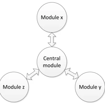
2.2.1 Centralised
In a centralised approach (see Figure 2.3), the central module is responsible for all decision-making related with planning and processing of information and issues commands to the modules around it. By requiring simpler coordinating algorithms, it eases management and control optimization. However, introducing modifications and adding new elements implies making changes to the program. Moreover, its total dependence on the central note, raises control complexity and response time, and lowers its fault tolerance.
2.2.2 Hierarchical
2.2. CONTROL APPROACHES 13
Module x
Central
module
Module z
Module y
Figure 2.3: Interactions in a centralised control architecture
difficult to introduce a new layer.
2.2.3 Modified Hierarchical
The modified hierarchical approach maintains all features of the hierarchical approach while adding interaction between modules at the same hierarchical level (see Figure 2.5), increasing their complexity. In this way, whenever there is a disturbance in the normal execution of the system, it might be solved with the information gathered at the level where it was detected and without involving upper levels, improving response. System expandability is also improved.
2.2.4 Heterarchical
14 CHAPTER 2. STATE OF THE ART, RELATED WORK AND SUPPORTING CONCEPTS
Module a
Module c Module b
Module y Module z Module x
Figure 2.4: Interactions in a hierarchical control architecture
2.3
Agent-Based Control
The heterarchical architecture, referred to in 2.2.4, is also designated by autonomous agent approach in the agent domain [Leit˜ao, 2004]. In this approach, the manufacturing system is controlled by a society of autonomous entities called agents which interact autonomously with the environment through the devices they control, and with one another through the exchange of messages. There are two levels of abstraction to be considered: the individual agent and the multiagent society.
2.3.1 Individual Agent
Wooldridge [2009] gives the following definition of agent:
”An agent is a computer system that is situated in some environment, and that is capable of autonomous action in this environment in order to meet its delegated objectives.”
2.3. AGENT-BASED CONTROL 15
Module a
Module c Module b
Module y Module z Module x
Figure 2.5: Interactions in a modified hierarchical control architecture
order to take action towards the realization of its functionality. Perception, decision and action are the keywords of agent behaviour.
2.3.2 Agent Typologies
An agent can be classified according to its behaviour as deliberative, reactive and hybrid [Wooldridge, 2009].
Deliberative Agent
A deliberative agent is an agent that behaves pro-actively towards the achievement of a predetermined goal. It maintains a knowledge representation of the world and, through reasoning, it is capable of planning a course of action, which comprehends the generation of a correct and optimal sequence of actions that take him closer to its goal [Leit˜ao, 2004].
The Belief-Desire-Intention (BDI) architecture is a well known deliberative agent architecture, which attempts to replicate human practical reasoning [Wooldridge, 2009]. In this architecture, the reasoning process that leads to decision-making takes in consideration the following representations:
• beliefs - Knowledge of the agent regarding itself and its environment.
• desires - Goals that the agent has to achieve, but does not know yet how to.
16 CHAPTER 2. STATE OF THE ART, RELATED WORK AND SUPPORTING CONCEPTS
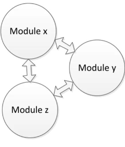
Module x
Module y
Module z
Figure 2.6: Interactions in a heterarchical control architecture
Reactive Agent
A reactive agent is an agent whose sole purpose is to respond to changes that occur in the environment, when they happen, producing robust actions. Unlike a deliberative agent, it does not have an internal knowledge representation.
Brooks [1986, 1991a,b,c] proposed the subsumption architecture for reactive agents, which is based on three thesis:
• Intelligent behaviour does not require explicit symbolic representations.
• Intelligent behaviour does not require explicit abstract symbolic reasoning.
• Intelligence is an emergent property of certain complex systems.
The basic ideas are that intelligence is in the world and not inside the agent. Moreover, intelligent behaviour arises from the interaction of the agent with its environment.
This architecture is a hierarchy of behaviours and each behaviour has a situation-action rule-like structure. Although behaviours compete with one another for the control of the agent, lower layers of the architecture, which represent more primitive kinds of behaviour, have precedence over layers further up the hierarchy Wooldridge [2009].
Hybrid Agent
2.3. AGENT-BASED CONTROL 17
However, depending on how the layers receive sensorial information and interact, this architecture can be classified as horizontal layering and vertical layering [Wooldridge, 2009].
In horizontal layering, the sensors are directly connected to the layers, which are directly connected to the output [Wooldridge, 2009]. This can create a problematic situation in which different layers give different orders to the output. [Barata, 2005].
In vertical layering, sensors and output connect to one layer each, which can happen in one of two ways. In ”one pass control” sensors are connected to the bottom layer and actuators are connected to the top layer; consequently, required information flows bottom-up, being filtered from layer to layer. In ”two pass control” sensors and actuators are connected to the bottom layer. Hence, information flows upwards and then downwards through the layers [Wooldridge, 2009]. In both situations, only one layer affects the output. Thus, the problem described in horizontal layering does not occur in this architecture. However, if one layer stops working, the whole architecture fails [Barata, 2005].
2.3.3 Multiagent Systems
Agents in a Multiagent System (MAS) have to interact with one-another. Wooldridge [2009] states that this interaction requires the abilities:
• coordination - Coordination is needed in the access to non-sharable resources.
• cooperation - Agents cooperate to achieve a common goal by working together.
• negotiation - The process of negotiation is required to reach agreements on matters of common interest.
The usefulness of these abilities is observable in a coalition, which is a structure that results from the association of at least two cooperating agents. Negotiation is required for the autonomous formation of coalitions, and coordination is required when performing a joint activity.
Coalition Formation
Sandholm et al. [1999] identified three activities in coalition formation:
• Coalition structure generation: the set of agents should be partitioned in coalitions in such a way that the agents inside a coalition coordinate their efforts with one-another but not with agents belonging to other coalitions.
18 CHAPTER 2. STATE OF THE ART, RELATED WORK AND SUPPORTING CONCEPTS
• Dividing the value of the generated solution among agents.
2.3.4 Communication Technologies
Agent interaction involves communication and understanding which is where ontologies (see 2.4), Agent Communication Languages (ACLs) and agent communication protocols play an important role.
Agent Communication Languages
ACLs provide formats for the exchange of messages between the agents in the MAS. There are two well known ACLs: Knowledge Query Manipulation Language (KQML), developed by the ARPA knowledge sharing initiative, and FIPA-ACL, developed by Foundation For Intelligent Physical Agents (FIPA). The structure of a message is similar in both standards, being composed of a performative, a content and a set of control parameters [FIPA, 1996 - 2002b]. Performative and content parameters are the two components of a speech act, as explained in speech act theory [Austin, 1975, Searle, 1997], and are used by agents to express their intentions to other agents. Some FIPA-ACL performatives are relevant to this work, such as: request, agree, refuse, inform, failure, cfp (call for proposals), propose, accept-proposal, reject-proposal and subscribe. KQML includes the Knowledge Interchange Format (KIF) language, which is used to express the content of messages.
Agent Communication Protocols
A communication protocol defines how agents should behave when communicating with one-another. They consist of an ordered sequence of messages that an agent should send, or wait for, at a given time during the communication process. FIPA defined a set of communication protocols, some of which are relevant to this work, such as: request interaction protocol, contract net interaction protocol, subscribe interaction protocol [FIPA, 1996 - 2002c,-,-]. The performative of a message sent or received is related with the protocol in use at that time and with its state of execution.
2.3.5 Integrating Agents In Custom Applications: The Jade Framework
2.4. ONTOLOGIES 19
2.4
Ontologies
An ontology is a formal specification of a set of terms used to describe and represent an area of knowl-edge. It is widely used in areas such as knowledge engineering, artificial intelligence and computer sci-ence in computer applications that involve knowledge management and information management [Barata and Onori, 2006]. In the context of this work, an ontology is used to define a set of classes of things, the properties of those classes and the relationships between them. Moreover, the classes and properties de-fined are instantiated to create a set of individuals which represent a knowledge base of the corresponding ontology domain.
Technologies available for developing ontologies include language specifications and editing tools. As for integrating ontologies in an application, there are libraries which can be imported into a program-ming environment and that make it easy to read and write ontology files.
2.4.1 Language Specifications: RDF and OWL
The two languages that are relevant to this work are Resource Description Framework (RDF) and Web Ontology Language (OWL), both developed by the World Wide Web Consortium (W3C). These lan-guages use syntax in the encoding of knowledge.
RDF
RDF is a standard for data interchange. In this language, a thing is represented as a resource which is identified by a Uniform Resource Identifier (URI). It encodes information in triple structures, which are composed of three URIs: URI of a resource, followed by the URI of a property, followed by a literal or the URI of other resource. Properties can have a literal or a URI as their value. This linking structure forms a directed labeled graph where the nodes represent resources and edges represent properties. This facilitates visualization and analysis of the ontology [RDF Working Group, 2009].
OWL
20 CHAPTER 2. STATE OF THE ART, RELATED WORK AND SUPPORTING CONCEPTS
or a datatype, such as: boolean, integer, double, string. The OWL Working Group has produced a W3C recommendation for OWL [OWL Working Group, 2004].
2.4.2 Editing Tools: Prot´eg´e
The editing tool used in the context of this work was Prot´eg´e, a free open source ontology editor and knowledge-base framework which supports OWL [Stanford Center for Biomedical Informatics Research, 2010]. The creator of an ontology can use the Graphical User Interface (GUI) of Prot´eg´e to write his ontology and then use the automatically generated files in a computer application or program. This editor supports the addition of third party plug-ins, which add new functionalities to the ones available by default, facilitating the process of creating an ontology.
2.4.3 Integrating Ontologies In Custom Applications: Jena Java API
Jena Semantic Web Framework For Java (Jena) [Jena] is a Java Application Programming Interface (API) which supplies methods for creation and manipulation of RDF graphs [McBride et al., 2009]. In Jena, graphs, resources, properties and literals are represented by Java object classes and interfaces. Moreover, a graph is called a model, an arc of a model is called a statement and each statement asserts a fact about a resource, which is accomplished by its three components: subject, predicate and object. These components correspond to the three components of a triple.
Jena also aims to provide a consistent programming interface for the development of applications which deal with ontologies [Dickinson, 2009]. One of the ontology languages it supports is OWL. However, the Jena ontology API is used equally for every language supported. It provides Java object classes for ontology classes, object properties, datatype properties and individuals. The value of an object property is an URI and the value of a datatype property is a datatype. The ontology is contained in an ontology model, which is an extension of the model used for RDF, as the information is still encoded in RDF triples. It also facilitates working with ontologies spread across different files as imports through a document manager.
2.4.4 Manufacturing Ontologies: EUPASS Ontology
2.5. GENETIC ALGORITHMS 21
2.5
Genetic Algorithms
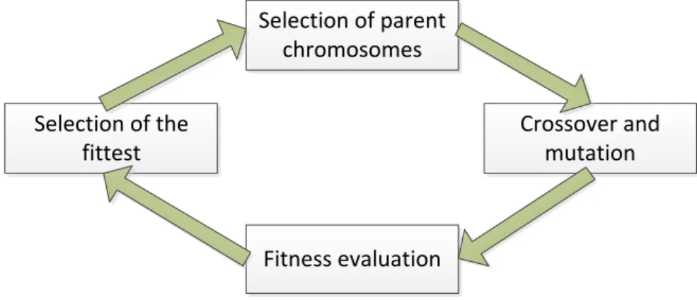
Genetic Algorithms (GAs) [Goldberg, 1989] are inspired by natural genetic evolution, the process by which nature produces new individuals different from their parents and that leads to the arising of new species. In this process, favourable individual differences and variations are preserved, and those that are injurious are destroyed, which is known as natural selection or survival of the fittest [Darwin, 2010]. In nature, genetic information of individuals is encoded in structures called chromosomes. When two individuals reproduce, their genetic information is combined to create new chromosomes, which contain genetic information used to generate a new individual.
A genetic algorithm is a simplified version of this process that uses data structures as its chromo-somes. In such an algorithm, a population of individuals undergoes a cycle of evolution (see Figure 2.7). Each iteration of this cycle comprises: selection of parent chromosomes, their duplication and crossover of the genes, mutation of the resulting offspring, and selection of the fittest who will remain for the next iteration. Its purpose is to search for an optimal solution to a given problem, which might not be the best. Heuristics can be used to fasten the search.
Selection of parent chromosomes
Crossover and mutation
Fitness evaluation Selection of the
fittest
Figure 2.7: A genetic algorithm evolution cycle
2.5.1 Encoding Information
22 CHAPTER 2. STATE OF THE ART, RELATED WORK AND SUPPORTING CONCEPTS
Chromosome
Gene 1 ... Gene n
Figure 2.8: The structure of a chromosome
2.5.2 Selection Of Parents
The process of reproduction requires the selection of multiple pairs of individuals to be the parents of new individuals, which will join the population for the following iteration. The most common algorithm used for this step is the roulette wheel, where each individual in the population is given a probability of being selected proportional to its fitness, which is used for randomly choosing pairs of parent chromosomes.
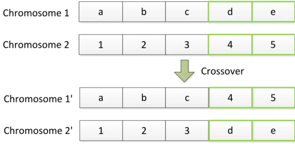
2.5.3 Crossover Operator
Crossover is the process by which the copies of two parents exchange sequences of genes from their chromosomes, in order to create two new individuals. Single point crossover, which is the most common type of crossover, consists of choosing a position in the gene sequence of one parent chromosome, being that such a position is designated as locus, and exchanging all genes from that point on to the other chromosome and vice-versa. Occurrence of crossover is dependent on a given probability. If it does not happen, the two chosen parent chromosomes are copied directly into the population.
1 2 3 4 5
a b c d e
Chromosome 1
Chromosome 2
1 2 3
5 4
a b c
e d
Chromosome 1'
Chromosome 2'
Crossover
2.6. MANUFACTURING SYSTEM DESIGN 23
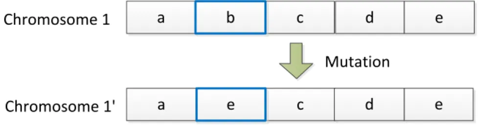
2.5.4 Mutation Operator
Mutation is the process by which the genes in a chromosome change their alleles with a given probability. This process consists of choosing a gene of the chromosome at random chance and changing its value to other possible value.
c c a b Chromosome 1 a e Chromosome 1' Mutation d d e e
Figure 2.10: Mutation effect
2.5.5 Fitness Evaluation
Only the fittest chromosomes of an iteration are kept to the following one. For this purpose, each chro-mosome is evaluated and given a fitness value. The ones which have the higher value are the ones that are kept. Evaluation is performed by an evaluation function, which returns a fitness value. This func-tion requires the decoding of the informafunc-tion encoded in the chromosomes. Decoding is the process of retrieving the real value of the information represented by the genes in a chromosome.
2.5.6 Integrating Genetic Algorithms In Custom Applications: JGAP
Java Genetic Algorithms Package (JGAP) [Meffert and Rotstan, 2002 - 2010] is a framework for genetic algorithms and genetic programming for the Java language. It provides basic genetic mechanisms that are useful in the application of evolutionary principles to problems that are to be computationally solved. It contains classes for chromosomes, genes, genetic operators and fitness functions that can be used or extended as it is necessary.
2.6
Manufacturing System Design
24 CHAPTER 2. STATE OF THE ART, RELATED WORK AND SUPPORTING CONCEPTS
and SO-systems increase system complexity and introduce new stages in its life cycle. SO principles in-troduce creation-time, a stage when the layout of the system is being generated by software. Intelligent supervising systems and SA principles introduce stages when the manufacturing plan is improved, mod-ified or replaced by other, and the system is reconfigured. EAS introduces the possibility for a system to evolve. This thesis addresses design time and creation-time issues, such as the choosing of the required equipment modules and the design of the shop floor layout.
The process of designing a manufacturing system consists of selecting production and material han-dling equipment, and determining a layout for this equipment, which are different problems on their own [Heragu and Kusiak, 1988]. Depending on the situation, manufacturing and material handling equip-ment can be selected and laid out at the same time, or manufacturing equipequip-ment can be first, followed by material handling equipment. The usage of one or other approach is dependent on each situation analysis [Heragu, 2006].
2.6.1 Equipment Selection
A designer must know what are the required types and quantities of manufacturing and support equip-ment before designing the machine layout. The required types of equipequip-ment can be determined by matching available equipment with the basic production processes required on product parts and materi-als to produce the final product [Heragu, 2006]. As for quantities of equipment, which is to be understood as the number of pieces of each type of equipment, the designer must account for sequencing of opera-tions and fault tolerance, which are relevant issues during run-time and are affected by this decision. If the right types and quantities of equipment are selected, then the costs of equipment purchase, opera-tion and maintenance will be efficient, machine utilizaopera-tion will be increased, and available space will be efficiently used [Heragu and Kusiak, 1987].
Tompkins et al. [2010] describes material handling equipment selection as a problem of ”providing the right amount of the right material, in the right condition, at the right place, at the right time, in the right position, in the right sequence, and for the right cost, using the right methods”. Properties and characteristics of materials, such as: size, weight, form, etc, must be considered when selecting material handling equipment. Heragu [2006] identifies several types of material handling devices: conveyors, palletizers, pallet lifting devices, trucks, robots, Automated Guided Vehicles (AGVs), hoists, cranes and jibs, and warehouse dedicated devices.
2.6.2 Equipment Layout
2.6. MANUFACTURING SYSTEM DESIGN 25
efficient layout design, the designer must consider: throughput rates, responsiveness, material handling efficiency, scope, scale, equipment and housing costs, reconfigurability, product life cycle, fault toler-ance, interactions with the environment, etc. A flexible, modular and reconfigurable layout might not need to be redesigned each time manufacturing requirements change. Relayout can be expensive and might require shutting down production [Benjaafar et al., 2002].
2.6.3 Layout Configurations
Depending on the situation, different types of layout can be used in the design of a manufacturing system. Product, process and cellular layouts are designed for a specific product mix and production volume that are supposed to last for a long period of time [Heragu, 2006].
Transfer/Flow Line Layout
In a transfer/flow line layout, workstations are layout in line, ordered according to the required sequence of operations. Consequently, during run-time, materials flow from one workstation to the next in a sequential manner. The execution of one operation is dependent on the finalization of the previous one, which means that the production rate is dependent on the slowest operation. The processing rate of workstations and transportation time between these can be planned in a way such that there is no need for buffer storage between workstations. Configurations for a transfer line include: straight-line flow, U-flow, circular flow, open field layout (see Figure 2.11). This type of layout is suitable for high-volume production. Although its production rates are unmatched by other types of layout, it is inflexible in the number of products manufactured and, in case of equipment failure, the complete system stops [Tompkins et al., 2010].
Centralised Layout
In a centralised layout, workstations are layout around the area where materials are transported. Materials enter and flow in this area, from workstation to workstation, as demanded by the required operations (see Figure 2.12), the sequence of which can be altered without modifying the layout. In case of equipment malfunction, and depending on the affected equipment, the system might remain partially operational [Tompkins et al., 2010]. Material handling system configurations that support a centralized layout are: uni-directional linear layout, spine layout, loop layout and star layout.
Functional Layout
vol-26 CHAPTER 2. STATE OF THE ART, RELATED WORK AND SUPPORTING CONCEPTS
umes, this layout presents inefficient material handling and complex scheduling, that results in poor lead times, poor resource utilization and limited throughput rates. Furthermore, changes in the product mix and/or routings, often require the redesign of the material handling system [Benjaafar et al., 2002]. This layout can be supported by a material handling system configured in ladder layout.
Cellular Layout
Manufacturing and material handling equipment can be grouped into cells, in which case the layout of the machines has to be determined within each cell as well as the layout of the cells. A cellular layout is suitable for manufacturing systems that produce a large number of components and for which manufacturing activities can be decomposed into almost mutually independent cells [Heragu, 2006]. This design approach simplifies workflow and reduces material handling; however, it can be highly inflexible to the introduction of new products, as it is designed for a fixed set of part families. Some variations of this layout try to surpass this limitations with overlapping cells and machine sharing [Benjaafar et al., 2002].
Distributed Layout
In a distributed layout, resources with the same type of functionality can be more or less distributed through the shop floor (see Figure 2.14). Consequently, accessibility to distributed types of resource is increased, as a result of shorter material travel distances, which makes this layout more efficient for a larger set of product volumes and mixes [Benjaafar et al., 2002].
Modular Layout
A modular layout is composed by a network of basic modules, which consist of groups of machines required for subsets of operations in different routings that are arranged into traditional layout configura-tions, such as: functional, transfer line or cellular, that minimize total flow distances or costs. To support evolution of the product mix and demand changes, modules can be added and eliminated. It is suitable for manufacturing multiple products [Benjaafar et al., 2002].
Reconfigurable Layout
2.7. GRAPHS 27
2.6.4 Layout Design With Genetic Algorithms
To and Ho [2002], To [2003] propose a GA for configuring reconfigurable conveyor-components in a flexible assembly line system. Their approach is a messy genetic algorithm in which a chromosome is a complete assembly line of conveyors. Each chromosome is composed of composite genes, which represent conveyor components, and each component gene represents a property of the conveyor, such as moving direction and rotational angle. In crossover, chromosomes exchange sequences of composite genes that may have different lengths, in which case the offspring chromosomes have a different length from what their parents had. Hence, the ”messy” part of the algorithm. When mutation takes place in a chromosome, characteristics, which are encoded in binary as genes, are altered. In fitness evaluation, the composite genes in a chromosome are decoded sequentially. The first composite gene represents the conveyor component closest to the loading station and the following represented conveyor components are assigned positions after that, according to the positions determined using geometric equations specific to the type of conveyor considered. The unknowns of these equations are the characteristics represented by genes and the result is a position for the next conveyor component. Each chromosome is evaluated using a set of fitness functions which, one by one, add to the fitness value of the chromosome, which is zero at first.
2.7
Graphs
Graphs are used in this thesis as a means of analysing the manufacturing system’s layout. Diestel [2006] gives the following definitions for graph, path and tree, which are the three relevant structures in the context of this thesis:
”A graph is a pair G= (V,E) of sets such thatE ⊆[V]
2; thus, the elements of E are 2-element subsets of V. ... The elements ofV are the vertices (or nodes, or points) of the graphG, and the elements ofE are its edges (or lines).”
”A path is a non-empty graphP= (V,E)of the form
V ={x0,x1, ...,xk} E={x0x1,x1x2, ...,xk−1xk},
where thexiare all distinct. The verticesx0andxkare linked byPand are called its ends; the verticesx1, ...,xk−1are the inner vertices ofP. The number of edges of a path is its length, and the path of lengthkis denoted byPk.”
28 CHAPTER 2. STATE OF THE ART, RELATED WORK AND SUPPORTING CONCEPTS
2.7.1 Integrating Graphs In Custom Applications: JGraphT
JGraphT [Naveh, 2003 - 2005] is a free Java graph library that provides mathematical graph-theory objects and algorithms. It supports various types of graphs, including: directed and undirected graphs, graphs with weighted / unweighted / labeled or any user-defined edges, etc. Graph vertices can be of any objects. Furthermore, it can be integrated with the JGraph [JGraph, 2001 - 2010] library, to enable graph visualization.
2.7. GRAPHS 29
U-flow
Circular flow Straight-line
Workstation Subtitle:
Flow direction
30 CHAPTER 2. STATE OF THE ART, RELATED WORK AND SUPPORTING CONCEPTS
Workstation
Subtitle:
Flow direction
Figure 2.12: Centralised layout
A
A
B
B
B
Workstation with functionality A
Subtitle:
A
A
B
B
D
C
C
C
D
D
A
B
C
D
Workstation with functionality B
Workstation with functionality C
Workstation with functionality D
Figure 2.13: Functional layout
A
A
B
B
B
Workstation with functionality A
Subtitle:
A
A
B
B
D
C
C
C
D
D
A
B
C
D
Workstation with functionality B
Workstation with functionality C
Workstation with functionality D
Chapter 3
System Architecture
The purpose of the developed system architecture is to support manufacturing system lay out based on a given product plan. Therefore, it was developed to support design, run-time and re-engineering phases. Modules, in an EAS context, are agents organised in a MAS and exhibit self-* capabilities. Knowledge and process control are distributed through the agents, as different agents have different roles in the manufacturing process, which they perform with a certain degree of autonomy, based on the knowledge they have of themselves, of other agents, and of the process. With this approach, should the need for re-lay out arise during an evolution stage, old modules can be removed and new modules can be added without reprogramming.
This chapter describes and explains the ideas followed and decisions taken during the development of the system architecture in sections with different points of view, focusing on the layout agent, which is the agent capable of performing layout design, and its interactions with other agents.
3.1
Control Approach
In the developed manufacturing system architecture, control results from the interactions between the agents in the MAS. As these interactions evolve, the architecture is able to adapt to different system life cycle phases.
3.1.1 Design Time
The first agent to be launched is the Directory Facilitator (DF), which is followed by resource agents, and then by the layout agent. Resource agents register to the DF and send it their characteristics and capabilities. The layout agent registers to the DF and requests information about the resource agents, which is used to design a layout for the manufacturing system by assigning positions to the resources controlled by resource agents (see Figure 3.1).
32 CHAPTER 3. SYSTEM ARCHITECTURE
Layout agent
DF agent Resource agent x
Resource agent y Resource
agent z
Figure 3.1: Information flow at the beginning of design time
After the positions have been assigned, each resource agent interacts with its neighbour agents, which are the ones that control resources that were assigned positions near its resource, to create coalitions (see Figure 3.2). It is over when it is not possible to create more coalitions. Resource agents update their registry information at the DF.
DF agent
Resource
agent x
Resource
agent y
Resource
agent z
Figure 3.2: Information flow at the end of design time
3.1.2 Run-Time
3.2. TYPES OF AGENTS 33
System agent
Resource
agent x
Resource
agent y
Resource
agent z
Actuators and sensors
DF agent
Figure 3.3: Control approach at run-time
3.2
Types of Agents
There are resource agents, a layout agent, a system agent, and a DF agent, in the MAS. They have different knowledge and different behaviours, that change throughout the life cycle of the system.
3.2.1 Resource Agent
A resource agent is initialised with an ontology file containing a description of what type of resource it has to become and a description of the physical device it controls. It contains an ontology model where this information is kept and from where it can be retrieved and used by the agent to create coalitions and to issue control actions to the device hardware. It offers its functionalities, as described in the ontology model, as skills to other agents, which can request their execution. Some resource agents have skills that can only be offered in a joint effort with other resource agents. In order to make these complex skills available, resource agents create coalitions with one-another, that are controlled by one of them.
3.2.2 Layout Agent
A layout agent is initialized with an ontology file containing a product manufacturing plan, which is kept in an ontology model inside the agent. It requests, to the DF, the descriptions of resource agents and keeps them in the ontology model. This knowledge is used, by the agent, to design the layout of the manufacturing system. Based on the layout designed, it assigns a position to each manufacturing resource, by sending a message to the corresponding agent.
3.2.3 System Agent
34 CHAPTER 3. SYSTEM ARCHITECTURE
keeps them in the ontology model. This knowledge is used, by the agent, to coordinate resources and coalitions when the plan is being executed.
3.2.4 Directory Facilitator Agent
The DF accepts registration requests from the layout agent, system agent and resource agents. Registered agents send it information, which it stores in an ontology model, and that other agents might request.
3.3
Agent Knowledge
The system knows what is the product to produce and what resources can be used to produce it through ontology files that are given to the agents when they are initialized, and that contain instances of an ontol-ogy that is common to all the agents in the system. This ontolontol-ogy is described in Chapter 4. The product is known through its manufacturing plan. Available resources are known through resource descriptions. The success of layout design is dependent on the quality of this information, as lack of information might cause layout design failure.
Knowledge is stored, reasoned with, and retrieved from an ontology model that exists inside all the agents. The scope and nature of the information contained in the ontology model of an agent depends on the type of agent: the layout agent and the system agent contain information related with the manu-facturing plan and with resource agents; and a resource agent contains information about the resource it controls, and about the agents that are part of its coalitions, if that is the case.
Knowledge is provided in OWL, which was chosen because it is a semantic language and the on-tologies and instances written in it can be integrated in applications through existing libraries, and easily understood and edited by users.
3.3.1 Manufacturing Plan
The manufacturing plan consists of a sequence of operations with the corresponding arguments (see Figure 3.4). It is supplied, by the user, to the system agent, as a workflow that might include parallel, concurrent and decision dependent operations. Arguments define the conditions by which an operation is to be performed (i.e., length, depth, rotation, velocity, etc.).
Activity 1 Activity 2 Activity 3
Start Finish
3.4. AGENT BEHAVIOURS 35
3.3.2 Resource Description
Resource knowledge consists of descriptions of manufacturing resources available to be used in the manufacturing process (i.e., conveyor belts, drillers, robots, cranes, etc.), including their properties and characteristics (i.e., size, weight, etc.), as well as their capabilities and functionalities (i.e., drill, solder, etc.). Capabilities are described as skill templates, which are skills that can only be performed if a set of predefined requirements are met. Capabilities have restrictions that are related to the characteristics of the resources (i.e., a driller with an arm of a certain length can drill only to a certain depth). Functionalities are described as agent skills whose requirements have been fulfilled.
Skills that require cooperation between resource agents are described as complex skills. Their de-scription includes the sequence of interactions that are required for their execution.
Resources have characteristics that are related with the physical connections that have to be estab-lished between the resources for the execution of complex skills (i.e., a conveyor belt holds the part while the driller drills a hole in it). The connection between two pieces can be established by overlapping their work volumes. This overlap creates an intersection volume from which one point is chosen as a con-nection point in the description of the resource. A direction by which this point can be accessed is also included in the description as a connection point orientation.
In Figure 3.5, the conveyor belt contains three connection points: cb:1 and cb:2 as input and output from and to other conveyor belts, and cb:3 in the middle of the belt surface, where it can hold a product part for the driller to work with. This third connection point is the connection point d:1 of the driller.
Driller Conveyor belt
cb:2 cb:3 ≡ d:1
cb:1
Subtitle:
Indicates the position and orientation of a
connection point
Figure 3.5: Connection points of resources
3.4
Agent Behaviours
The way in which agents behave throughout the manufacturing system life cycle is dependent on the agent behaviours that they are executing inside. Each type of agent has its own set of behaviours, which change throughout each stage of the life cycle.