Switched Unfalsified Multicontroller
Nonparametric model based design
Fernando Coito, Luís Brito Palma
Departamento de Engenharia ElectrotécnicaFaculdade de Ciências e Tecnologia, UNL 2829-516 Caparica, Portugal [email protected], [email protected]
Fernando Costa
Departamento de Engenharia Electrotécnica Faculdade de Ciências e Tecnologia, UNL
2829-516 Caparica, Portugal [email protected]
Abstract— In this paper, we present a controller design strategy for the implementation of a multicontroller structure for single-input single-output (SISO) plants. The overall control system can be viewed as a feedback interconnection of a SISO plant, a set of candidate controllers and a switched selection scheme that supervises the switching process among the candidate controllers. The switching scheme is designed without explicit assumptions on the plant model, based on the unfalsified control concept introduced by Safonov [1,2]. A switched multicontroller structure is implemented and experimental results are presented.
switched control; fractional orderl control; adaptive control,
I. INTRODUCTION
Dealing with nonlinear systems is an inherently difficult problem. As a consequence models and analysis of nonlinear systems will be less precise than for the simpler linear case. Thus, one should look for model representations and tools that utilize less precise system knowledge than the traditional approaches. This is indeed the trend in the area of intelligent control where a range of approaches, such as Fuzzy Logic, Neural Networks and Probabilistic Reasoning are being explored [3, 18]. The current paper uses operating regime decomposition for the partitioning of the operating range of the system in order to solve modeling and control problems.
A. Unfalsified switching control
The operating regime approach [5, 15-17] leads to multiple-model or multiple controller (multiple model control – MMC) synthesis, where different local models/controllers are applied under different operating conditions, see Fig. 1. One version of the above strategy is to represent the global system operation as a family of smaller local regions, where the supervisory controller alters the controller according to the current local region in which the process is operating. It must be stressed that this strategy holds only if the nonlinear system can be represented as a Linear Parameter varying (LPV) system.
The switching is orchestrated by a specially designed logic that uses the measurements to assess the performance of the candidate controller currently in use and also the potential performance of alternative controllers.
In performance-based supervision the supervisor attempts to assess directly the potential performance of every
candidate controller, without estimating the model of the process [1, 2, 4, 17]. To achieve this, the supervisor computes performance signals that provide a measure of how well the controller Ci would perform in a conceptual experiment, in which the actual control signal u would be generated by Ci as a response to the measured process output
y. This approach is inspired by the idea of controller unfalsification [1].
Using the unfalsification concept, no assumptions on the plant structure are required. The best controller among a set of candidate is selected straight from input/output data. The performance of all candidate controllers is evaluated directly, at every time instant, without actually inserting them in the feedback loop. Controllers that prove to be unable to drive the system according to the desired closed loop dynamics are entitled falsified. Only unfalsified controllers are candidate to actually control the process. Thus, switching between candidate controllers is based directly on their performance.
B. Controller design
A key feature over the unfalsified control approach is the separation between the supervisor switching policy, and the controllers design and tuning procedure. Apart for some causality constrains, there are no relevant restrictions on individual controller structures. In fact, different controller structures may be combined into a single unfalsified switched multicontroller.
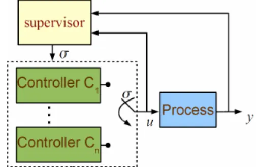
Figure 1. Switching control. The switching decision between the controllers is performed trough the switching signal σ.
same closed loop specifications, usually in the form of the behavior from a reference model to be tracked. This makes its use within muti-loop control structures quite interesting, as it provides a level of decoupling between loop dynamics and the process operation conditions.
Within this framework different approaches towards the development of such a multicontroller were developed. In this paper the set of controllers is designed from experimental frequency response data, through a frequency domain optimization procedure.
II. THE UNFALSIFIED MULTICONTROLLER There is vast literature on supervisory control, mainly for process estimation based schemes. Among those based in process estimation using Certainty Equivalence, interesting references are [6, 7, 8, 9], while for or Model Validation based schemes some relevant papers are [10,11]. Also, a very interesting tutorial may be found in [5] where an attempt is made to integrate the different approaches within a unified framework.
As for performance evaluation based algorithms, and specially unfalsified control, some important references are [1,2,4,12].
It is well known that switching among stabilizing controllers can easily result in an unstable system [9, 47]. To avoid a possible loss of stability the switching logic must prevent “too much” switching, which can be achieved through dwell-time strategy [13, 4].
A. Unfalsified controllers
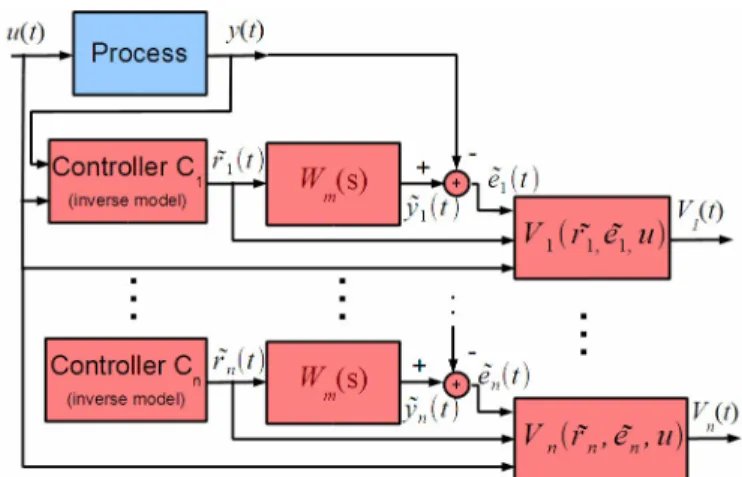
Consider that the process to be controlled is unknown and that the only available information are the past values from the set-point (r), the output (y) and the control action (u). The aim is to determine if a controller is capable to lead the closed loop system to behave according to some predefined reference model Wm.
It is assumed that there is a number of predesigned “causally-left-invertible” controllers Ci (in the sense that the current value of ri(t) is uniquely determined by past values of
u(t) and y(t)), among which at least one is able to fulfill the specification. After Safonov [1] performance criterion (1) is used to evaluate discrete time controllers.
V
(
r
˜
,
u
, ˜
e
,
t
)
=
˜
e
t+
λ
u
t˜
r
tif
r
˜
t≠
0
∞
if
r
˜
t=
0 and ˜
e
t+
λ
u
t≠
0
0
if
e
˜
t+
λ
u
t=
0
(1)
were is a parameter (>0) and the norm is
x
t=
ρ
τx
T(
τ
)
x
(
τ
)
0
t
; is a used a an exponential
forgetting factor (< 1).
At each moment, the controller performance is evaluated for all Ci according to the procedure (see also Fig. 2):
• The plant is to be under control of a stabilizing controller, even if its performance is poor.
• From past input/output data compute a fictitious set-point signal
r
˜
i(
t
)
=
r
˜
i(
C
i,
u
(
τ
)
τ≤t,
y
(
τ
)
τ≤t)
for each controller Ci. This corresponds to the set-point signal for which, taking into account y(t), the controller would have produced the actual control action u(t).• For each controller compute the fictitious output signal
y
˜
(
t
)
, corresponding to the output of the reference model Wm, when the fictitious set-point signalr
˜
i(
t
)
is used.• For each controller compute the fictitious error
˜
e
i(
t
)
=
y
˜
i(
t
)
−
y
i(
t
)
.• For each controller evaluate the performance function
V
(
r
˜
,
u
, ˜
e
,
t
)
.• From controller Ci performance
V
(
r
˜
i,
u
, ˜
e
i,
t
)
together with a performance threshold γ, the controller is said to be falsified by the available data at time t, if V
(
r
˜
i,
u
, ˜
e
i,
t
)
>
γ
.B. Switch limiting strategy
Only unfalsified controllers are candidates to control the process, which means that each individual controller yields a stable closed loop system. At each moment the controller selected is the one yielding the least performance index. Stability problems related to fast switching of the active controller [9, 7], are avoided by a switch limiting strategy is. The most common solution is the use of a dwell-time. The results from the paper, however, are obtained using the following a switching offset scheme:
• When controller Ci is in use, the switching only takes place if some other controller performance index gets below
V
(
r
˜
i,
u
, ˜
e
i,
t
)
−
γ
s. This offset value is usually obtained form experiments.C. Frequency input-output modelling
The experimental results presented on this paper are obtained over a lab-scale heat/ventilation experiment (Fig. 3). The process consists of a fan that blows air through a tunnel. At the tunnel inlet an electrical resistor heats up the air. The air temperature is measured at the middle of the tunnel. Decreasing the fan speed leads to higher measured temperatures and slower dynamics. A higher fan speed has the opposite effect. Three operation regimes are considered according to fan speed: low, medium and high speed.
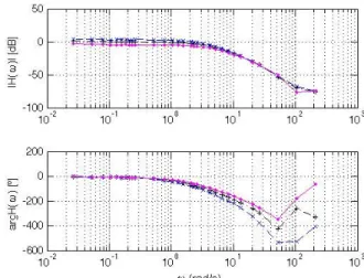
With low noise processes, by using experimental frequency response to characterize the dynamic behavior over selected operating points it is possible to obtain models (non-parametric) that are close to the process true behavior. From such models controllers may be designed by classical frequency based methods (Nyquist plot, lead-lag compensation, etc.), or by optimization over the frequency based algorithms [14]. The plant behavior is presented in Fig. 4, for the selected operating conditions.
D. Controller design
Each of the process models is used to design a closed-loop controller. The design goals are the same for all the pairs {controller, model}: i) a closed-loop behavior yielding an overshoot of 3% and a rise-time under 1 second; ii) small tracking error both in steady state and for frequencies under 0.3 rad/s; iii) the control action is desired to have low high speed content; iv) closed-loop stability.
To comply with these specifications, the controller is design through an optimization procedure. Let H(ω) be the process, C(ω) the controller, Gcl(ω) the designed closed-loop behavior and Gspec(ω) the desired closed-loop behavior. Then function
J
1=
1
−
G
cl( )
ω
iG
spec( )
ω
iωi<20
, (3)
Figure 3. Lab-scale heat/ventilation experiment used for tests.
Figure 4. Lab-scale heat/ventilation experiment frequency response for low speed (-x-blue), medium speed (- -black) and high speed
(−•−magenta).
weights the overall frequency behavior, related to specification i).
The tracking error is weighted by
J
2=
1
−
G
cl( )
ω
i ωi<0.3, (4)
and the function
J
3=
H
( )
ω
i1
+
C
( )
ω
iH
( )
ω
i ωi∈[1;5], (5)
is used to reduce the high frequency content of the control action. A 2nd order controller with the following structure is is considered:
C
(
s
)
=
k
1
+
s
z
11
+
s
z
21
+
s
p
11
+
s
p
2(6)
The controller is designed in order to optimize the function J=J1+J2+J3, with the constrain that the overall closed-loop system must be stable. Table I presents the results from the design procedure.
TABLE I. CONTROLLERS
Op. point Integer order controller Low sp.
39.2 1
(
+s2.89)
2
1+s0.04
(
)
(
1+s8.06)
Mediumsp. 136 1
(
+s2.29)
2
1+s0.0154
(
)
(
1+s3.19)
High sp.261 1
(
+s3.02)
(
1+s7.63)
1+s0.016
(
)
(
1+s8.22)
In Fig. 5 the designed closed-loop behavior Gcl(ω) is compared with the specified behavior Gspec(ω). The closed-loop gain tracks closely the objective. The phase diagram is also close to the objective for frequencies below 10 rad/s. For higher frequencies the system gain lies bellow -20 db, thus the phase shift does not affect the performance.
In Fig. 6 the fractional transfer function is compared with the integer order controller that approximates it. The second order controller gives a good approximation to the fractional one.
The results presented in these figures are relative to the middle operation point, but similar results are achieved for the other operating conditions.
The work presented uses a standard particle swarm optimization algorithm to perform function minimization.
III. IMPLEMENTATION AND TEST
A. Individual controoptimizationance
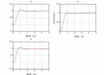
In Fig. 7 experimental step responses for each of the operation points are compared with simulation results. The figure illustrates the performance achieved by applying the correct (tuned) controller. In each of the tests the use of a different fan speed leads to different process dynamic. Nevertheless, the use of an operation point tuned controller produces similar closed-loop performance.
Figure 5. Fractional controller design for the middle operation point.
Figure 6. A comparison between the fractional transfer function and the integer order controller that approximates it (middle operation point).
In Fig. 6 the fractional transfer function is compared with the integer order controller that approximates it. The second order controller gives a good approximation to the fractional one. To illustrate the need for multiple controllers a set of tests is performed, in which each of the designed controllers is applied to the process at one of the operating conditions, and the closed-loop step response is evaluated. This procedure is repeated for the three operation points.
Some relevant results from this set of tests are presented in Fig. 8. Test a) shows that using a fan speed that is lower than the speed for which the controller is tuned may lead to an unstable closed-loop behavior. The opposite results also in poor performance, as exemplified by test b) where the low speed tuned controller yields long rise and settling times.
The tests show that it is not possible to achieve a performance close to the desired with a single fixed-parameter linear controller.
Figure 7. Experimental closed-loop step response at different operating conditions, using the tuned controller: (green) experimental result; (red) expected behavior. a) low fan speed; b) middle fan speed; c) high fan
a) b)
Figure 8. Closed-loop step response at different operating conditions: a) fan at low speed with a high speed tuned controller; b) fan at high speed
with a low speed tuned controller.
B. Unfalsified switched controller
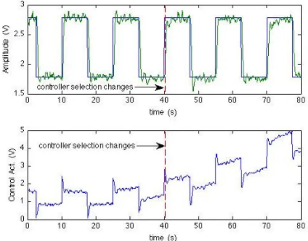
A switched controller structure, combining the set of tuned controllers and an unfalsified based supervisor, is applied to the heat/ventilation experiment. Fig. 9 and Fig. 10 show the result from a test in which the fan speed is smoothly increased from the minimum to the middle speed range. The air temperature set-point is given by a 0.04 Hz square signal, with amplitude 1V and offset 2.25V. Fig. 9 shows the air temperature sensor signal and the control action signal. While the temperature signal follows the set-point, with no significant change on the performance, the control action is increasing. This is expected, as the process gain is lower at high fan speeds, requiring higher heating power (control action) for the same set-point.
The test is stopped when the control action reaches the maximum value (5V). To perform the test at a higher fan speed range the set-point offset as to be reduced.
Fig. 10 shows the three Vi performance indexes, used for the selection of the active controller. As the fan speed increases the performance indexes relative positions change. At the beginning of the test the low fan speed index is the smallest and the high fan speed is the highest. Close to moment 40s there is a change in the relative position and the middle fan speed becomes the smallest one.
Figure 9. Supervisory control test: Process output and the control action. The fan speed is slowly increased fromthe the minimum to the middle
speed range.
Figure 10. Supervisory control: Performance indexes and controllser selection. The fan speed is slowly increased fromthe the minimum to the
middle speed range.
Figure 11. Supervisory control test: Process output and the control action. The fan speed is slowly decreased fromthe the maximum to the middle
speed range
Figure 12. Supervisory control: Performance indexes and controllser selection. The fan speed is slowly decreased fromhigh to the middle speed
Shortly after the index crossing, the selected controller commutes from the one tuned for low fan speed to the controller tuned for middle fan speed, maintaining the systems good closed-loop performance.
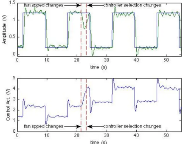
Fig. 11 and Fig. 12 present the results for a similar test, for a slowly decreasing fan speed. The set-point signal is like the one from the previous test, but its offset is 1.2V. The fan starts at high speed and the test stops when the control action reaches the minimum allowed value (0V). The controller selection changes at moment 48.8s.
The closed-loop performance is similar to the previous test except for the two steps closer to the selector change, which present significant overshoot. Observing Fig. 12, it is noticed that, within the time period corresponding to these steps, the performance indexes Vhigh and Vmiddle are close to each other. Fig. 13 shows a test where the operation point suddenly changes from middle fan speed to high fan speed range. This change occurs at moment 21.3s. This causes a large decrease on the process output. The controller reacts with a strong increase on the heating power signal. Within 3s the output temperature signal is back to the value previous to the fan speed step change.
It takes 1.8s for the supervisor to react and adjust the controller selection.
IV. CONCLUSIONS AND FURTHER WORK
The switched multicontroller structure described shows to present good performance and fast reaction to modifications on the operating conditions.
An important feature is that no previous knowledge on the plant dynamics is required to implement the unfalsified
Figure 13. Supervisory control: Process output and the control action. The fan speed is suddenly increased fromthe middle speed range into high
speed.
control-switching scheme. As the performance evaluation algorithm does not require a specific controller structure, it can be used with a broad range of controllers, and its possible to combine controllers with different structures into a single switched multicontroller.
Once the control-switching scheme requires no process model, an interesting development is to design the controllers without using any process parametric models. In the paper, this done through the use of experimental frequency response to characterize the dynamic behavior over the operating range.
REFERENCES
[1] M. G. Safonov, and T.-C. Tsao, “The Unfalsified Control Concept and Learning”, IEEE Trans Aut. Cont. vol. 42, pp. 843—847, 1997). [2] M. G. Safonov, and F. B. Cabral, “Fitting controllers to data”, Syst. &
Cont. Letters, vol. 43, pp. 299—308, 2001.
[3] L. B. Palma, F. J. Coito, and R. A. Neves-Silva, “Robust Fault Diagnosis Approach using Analytical and Knowledge-Based Techniques Applied to a Water Tank System”, Int. J. Eng. Int. Syst. for Elect. Eng. and Comm., vol. 13, pp. 237-244, 2005.
[4] R. Wang, and M. G. Safonov, “Stability of Unfalsified Adaptive Control”, Proc. 2005 American Control Conference, pp. 3162—3167, 2005.
[5] J. P. Hespanha, “Tutorial on supervisory control”, Technical report, Dept. of Electrical and Computer Eng.,
[6] A. S. Morse, “Supervisory control of families of linear set-point controllers—part 1: exact matching”, IEEE Trans. on Automat. Contr., vol. 41, pp. 1413–1431, 1996.
[7] A. S. Morse, “Supervisory control of families of linear set-point controllers—part 2: robustness”, IEEE Trans. on Automat. Contr., vol. 42, pp. 1500–1515, 1997. University of California, Santa Barbara, 2001.
[8] K. S. Narendra, and J. Balakrishnan, “Adaptive control using multiple models”, IEEE Trans. on Automat. Contr., vol. 42, pp. 171–187, 1997.
[9] J. P. Hespanha, and A. S. Morse, “Certainty equivalence implies detectability”, Syst. & Contr. Lett., vol. 36, pp. 1–13, 1999.
[10] R. Kosut, M. Lau, and S. Boyd, “Set-membership identification of systems with parametric and nonparametric uncertainty”, IEEE Trans. on Automat. Contr., vol. 37, pp. 929–941, 1992.
[11] R. Kosut, “Uncertainty model unfalsification: A system identification paradigm compatible with robust control design”,. Proc. of the 34th Conf. on Decision and Contr., pp. 3492–3497, 1995.
[12] J. van Helvoort, B. de Jager, and M. Steinbuch, “Data-driven multivariable controller design using Ellipsoidal Unfalsified Control”, Syst. & Cont. Letters, vol. 57, pp. 759–762, 2008.
[13] D. Liberzon, and A. S. Morse, “Basic problems in stability and design of switched systems”, IEEE Contr. Syst. Mag., vol.19, pp. 59–70, 1999.
[14] F. J. Coito, and M. D. Ortigueira “Fractional Controller Design Trough Multi-Objective Optimization”, Proc. 8th Portuguese Conf. on Aut. Cont. – CONTROLO’2008, 2008.
[15] A. P. Deshpande, and S. C. Patwardhan, “Online Fault Diagnosis in Nonlinear Systems Using the Multiple Operating Regime Approach”, Ind. Eng. Chem. Res., vol. 47, pp. 6711–6726, 2008.
[16] T. A. Johanson, and R. Murray-Smith, "The Operating Regime Approach", In: Multiple Model Approaches to Modelling and Control. T. A. Johanson, and R. Murray-Smith, Eds., Taylor and Francis: London, 1997, pp 3-71.
[17] F. Costa, F. Coito and L. Palma, “Switched Unfalsified Multicontroller”, IFIP Advances in Information and Communication Technology, vol. 349, Technological Innovation for Sustainability, pp 393-401, 2011.