ICEUBI 2015
*Open Access
Manuel Braz César* and Rui Carneiro Barros
ANFIS optimized semi-active fuzzy logic controller
for magnetorheological dampers
DOI 10.1515/eng-2016-0075
Received March 31, 2016; accepted October 31, 2016
Abstract:In this paper, we report on the development of a neuro-fuzzy controller for magnetorheological dampers using an Adaptive Neuro-Fuzzy Inference System or AN-FIS. Fuzzy logic based controllers are capable to deal with non-linear or uncertain systems, which make them partic-ularly well suited for civil engineering applications. The main objective is to develop a semi-active control sys-tem with a MR damper to reduce the response of a three degrees-of-freedom (DOFs) building structure. The control system is designed using ANFIS to optimize the fuzzy in-ference rule of a simple fuzzy logic controller. The results show that the proposed semi-active neuro-fuzzy based controller is effective in reducing the response of structural system.
Keywords:Fuzzy logic, MR damper, Semi-active control
1
Introduction
Neuro-adaptive learning techniques represent a simple methodology for the fuzzy modeling procedure to learn in-formation about a dataset in order to compute the mem-bership function parameters that best allow the associated fuzzy inference system to track a given input/output data. ANFIS uses a hybrid learning algorithm that combines the back-propagation gradient descent and least squares methods to create a fuzzy inference system whose mem-bership functions are iteratively adjusted according to a
*Corresponding Author: Manuel Braz César:Department of Ap-plied Mechanics, Polytechnic Institute of Bragança and LESE - Lab-oratory for Earthquake and Structural Engineering, Faculty of Engi-neering of the University of Porto, Department of Civil EngiEngi-neering, Porto, Portugal, E-mail: [email protected]
Rui Carneiro Barros:Department of Civil Engineering, Faculty of Engineering of the University of Porto and LESE - Laboratory for Earthquake and Structural Engineering, Porto, Portugal, E-mail: [email protected]
*International Conference on Engineering 2015 ś 2ś4 Dec 2015 ś
University of Beira Interior ś Covilhã, Portugal
given set of input and output data [1, 2]. The schematic of ANFIS architecture is shown in Figure 1.
Figure 1:Adaptive Neuro-Fuzzy Inference System or ANFIS.
Soft computing methods represent a relatively recent modeling technique of control devices and controllers that have been shown to be effective in dealing with complex and non-linear behavior of structural control systems. The development of a neuro-fuzzy model for a control device or neuro-fuzzy based controller typically involves four main steps:
1. Definition of input variables and the corresponding fuzzy inference system (FIS) membership functions (the FIS output is the desired control signal); 2. Selection of experimental or artificial data sets to
generate training and checking data;
3. Use of ANFIS optimization algorithm for training the FIS membership function parameters to model the set of input/output data by mapping the relation-ship between inputs and outputs in order to gener-ate a fuzzy model of the systems;
4. Validation of the resulting fuzzy model.
The process begins by obtaining a training data-set and checking data sets. The training data is used to find the premise parameters for the membership functions (MFs are dependent on the system designer).
thresh-old value. The checking data set can then be used to com-pare the model with the actual system.
The fuzzy model is obtained after ANFIS training pro-cess and is based on the training data, training options and type/number of membership functions previously de-fined by the user.
2
Numerical simulation
Consider a semi-active controlled system subjected to an earthquake ground motion with a control force applied to the first mass (or the first DOF, x1) as illustrated in Figure 2.
The control force provided by a MR damper intends to re-duce the response of the system and can be achieved plac-ing an actuator between the base and the first mass. The damper force can be changed using a control system com-prising a controller that monitors the system response and computes the required damping force that should be ap-plied to the system changes the system response in order to improve its structural performance. An effective semi-active control system involves an appropriate control al-gorithm that can take advantage of the dissipative proper-ties of the control device, i.e., the MR damper [3, 4]. There are several approaches available in the literature to control semi-active devices including soft computing techniques such as neuro-fuzzy controllers.
Figure 2:Schematic representation of a 3DOFs system under earth-quake excitation - Semi-active control with a MR damper at the first floor.
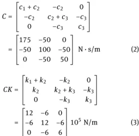
In what follows, the results of the neuro-fuzzy semi-active control system are compared with the uncontrolled, passive OFF and passive ON responses to evaluate the ef-ficiency of the semi-active control scheme in reducing the structural response. The mass, damping and stiffness ma-trices of the model structure are given by
M= ⎡
⎢ ⎣
m1 0 0
0 m2 0
0 0 m3
⎤
⎥ ⎦=
⎡
⎢ ⎣
100 0 0
0 100 0
0 0 100
⎤
⎥
⎦ kg (1)
C= ⎡
⎢ ⎣
c1+c2 −c2 0
−c2 c2+c3 −c3
0 −c3 c3
⎤
⎥ ⎦
= ⎡
⎢ ⎣
175 −50 0
−50 100 −50
0 −50 50
⎤
⎥
⎦ N·s/m (2)
CK= ⎡
⎢ ⎣
k1+k2 −k2 0
k2 k2+k3 −k3
0 −k3 k3
⎤
⎥ ⎦
= ⎡
⎢ ⎣
12 −6 0
−6 12 −6
0 −6 6
⎤
⎥ ⎦10
5N/m (3)
In this study, the structure will be subjected to theEl Cen-troground motion (1940 N-S component with a peak accel-eration of 3.42 m/s2). Since the mechanical system seeks to represent a small-scale building, the earthquake signal needs to be decreased to represent the magnitude of dis-placements that would be observed in experimental tests. Thus, the time was scaled to 20% of the full-scale earth-quake time history as shown in Figure 3.
Figure 3:Time-scaled El-Centro NS earthquake ground motion (0.2 t).
The state space equation of motion is given by
˙
z(t)(6×1)= [︃
0(3×3) I(3×3)
−M−1K
(3×3) −M−1C(3×3) ]︃ {︃
X(t)(3×1) ˙X(t)(3×1) }︃
+ {︃
0(3×1)
−λ(t)(3×1) }︃
¨ x(t) ⏟ ⏞ El Centro NS
(4)
where the column vector λ represents the location of the earthquake excitation (i.e., the seismic acceleration). Equation 4 can be written in a simplified form as
˙
z(t)(6×1)=A(6×6)z(t)(6×1)+E(6×1)¨xg(t) (5)
in which matrixArepresent the system matrix
A(6×6) = [︃
0(3×3) I(3×3)
−M−1K(3×3) −M−1C(3×3) ]︃
andEis the disturbance locating vector given by
E(6×1)={0, 0, 0,−1,−1,−, 1}T (7)
The response of the system can be computed using the state space output vectory(t)
y(t) =Cz(t) +Du(t) (8)
If the system displacements, velocities and accelera-tions are required, then
C(9×6)= ⎡
⎢ ⎣
I(3×3) 0(3×3) 0(3×3) I(3×3)
−M−1K(3×3) − M−1C(3×3)
⎤
⎥ ⎦,
D(9×1)= {︃
0(6×1)
−λ(3×1) }︃
(9)
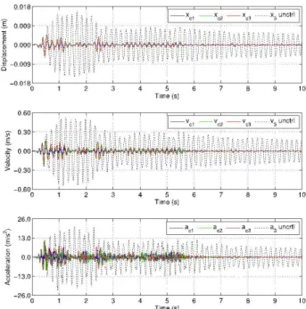
Using the state space formulation, the uncontrolled re-sponse of the 3DOFs system under the earthquake ground motion is displayed in Figure 4. It should be noted that the response was obtained with a high excitation level of the
El Centroearthquake achieved by scaling up the amplitude of the earthquake signal in 150%.
Figure 4:Uncontrolled response of the 3DOFs system.
The structure is equipped with a semi-active control system comprising a MR damper (Lord RD-1005-03 model) located between the ground floor and the first floor. The MR damper can operate in two modes:
1. As a passive energy dissipation device, i.e., without a control system (the properties of the actuator are constant during the simulation);
2. As a semi-active actuator whose control action is be-ing commanded by a neuro-fuzzy based controller. In this case, the modified Bouc-Wen model was se-lected to simulate the behavior of the MR damper.
The numerical formulation and the corresponding model parameters are presented in Table 1 [5]. Besides, the first-order time lag involved in the current driver/electromagnet during a step command signal must be included in the nu-merical model of the device, which in this case is defined by a first order filter (η=130 sec−1).
The equation of motion of the controlled structure can be defined by a state space formulation as
˙
z(t)(6×1)=A(6×6)z(t)(6×1)+Bc(6×1)fc1(t) +E(6×1) ¨zg(t) ⏟ ⏞ El Centro NS
(10)
whereBcis an additional matrix accounting for the
posi-tion of the control forces in the structure andfcis a column
vector with the control forces. The location of the control forces is defined by a location matrixΓwithinBc. In this
case there is only one control force applied to the first mass and therefore, it follows that
Γ(3×1)={1, 0, 0}T (11)
and then
Bc(6×1) {︂
0, 0, 0,− 1
m1, 0, 0 }︂T
(12)
Equation 10 can be written in a more compact form given that
B(6×2)= [Bc(6×1)+E(6×1)] = ⎡
⎢ ⎢ ⎢ ⎢ ⎢ ⎢ ⎢ ⎣
0 0
0 0
0 0
− 1 m1 −1
0 −1
0 −1
⎤
⎥ ⎥ ⎥ ⎥ ⎥ ⎥ ⎥ ⎦
u(t)(2×1)= {︃
fc1(t) ¨ xg(t)
}︃
(13)
and finally
˙
z(t)(6×1)A(6×6)z(t)(6×1)+B(6×2)+u(t)(2×1) (14)
The response of the system can be determined using the state space output vector
y(t)(9×1)=C(9×6)z(t)(9×1)+Dc(9×1)fc+F(9×1) ¨xg(t) ⏟ ⏞
Table 1:Modified Bouc-Wen model - Parameters of the RD-1005-3 MR damper [5].
F=c1y˙+k1(x−x0)
˙
y= 1
c0+c1
[αs+c0x˙+k0(x−y)]
˙
s=−β|x˙|z|z|n−1−γx˙|z|nδx˙
Current independent δ[-] β[mm2] γ[mm2] k0[N/m] f0[N] n
paramaters 10.013 3.044 0.103 1.121 40 2 Current α(I) =−826.671I3+ 905.14I2+ 412.52I+ 38.24[N] dependent c0(I) =−11.73I3+ 10.51I2+ 11.02I+ 0.59 [N·s/mm]
parameters c1(I) =−54.40I3+ 57.03I2+ 64.57I+ 4.73[N·s/mm]
3
Semi-active control using a
neuro-fuzzy controller
A fuzzy logic based controller was designed by using AN-FIS modelling capabilities to find the nonlinear map that best fits the expected response of the control system. The fuzzy controller was developed based on the numerical re-sults of the LQG controller whose response is used to de-fine the training data-set for the neuro-fuzzy optimization procedure with ANFIS. Floor accelerations and the dis-placement across the MR damper are the responses of the controlled system used by the LQG controller to determine the desired control force. The control signal is determined from the predicted control force using an inverse Bingham model of the MR damper. The system responses and the de-sired control signal were recorded and then used to train the neuro-fuzzy controller.
The data-sets for training and validation were ob-tained by numerical simulations exposing the LQG con-trolled system to a set of amplitude-scaled versions of the ElCentro NS earthquake excitation (i.e., 100 gal, 200 gal, 335 gal and 500 gal seismic accelerations).
The LQG controller combines a LQR algorithm with a Kalman filter estimator. In this case the optimal controller uses floor accelerations and the displacement across the damper as the measured system outputs in determining the control signal. Identically distributed Gaussian white noise is used to simulate acceleration noise measure-ments. The LQR determines the state feedback and the
Kalman filter estimates the state vector of a noisy sys-tem. Regarding the LQR controller, the state gain matrix
Gis tuned through the weighting matricesQandr. In the present example different configurations of these param-eters were evaluated by measuring the effect of each com-bination in the system response. The following weighting parameters provided the best performance in reducing the structural response
Q=
[︃
K(3×3) 0(3×3)
0(3×3) 0(3×3)
]︃
; R=r= 5×10⁻⁷ (16)
The observer gain Lmust be adjusted to achieve the re-quired performance. A high gain allows the filter to follow the observations more closely while a low gain follows the predictions more closely. This is accomplished by setting
Qw=qwIe, Rv=rvIm (17)
whereIeandImare identity matrices related with the
num-ber of excitation inputs and measurement signals, respec-tively. A common approach is to set one of the tuning pa-rameters (e.g.,rv=0.001) and adjust the other parameter
until the result is satisfying. In this caseIc = 1(¨xg) and Im=I4×4(x,x¨1,¨x2,¨x3).
Figure 5:Uncontrolled response of the3DOFs system.
epochs are the parameters involved in the ANFIS optimiza-tion procedure. The optimal number of membership func-tions (MFs) was defined through a trial and error process. In this case, six bell-shaped MFs were used to model each input variable (first and third floor velocities). The resul-tant fuzzy surface is shown in Figure 5.
It can be seen that when the first and third floor veloc-ities are large and have the same signs, the required con-trol signal that produces the damping force is also large. When both velocities are large but have opposite signs, the fuzzy controller delivers the lowest control signal. Be-sides, the minimum damping force requirement is located around the central zone comprising small floor velocities. It should be noted that the fuzzy controller can be en-hanced using other excitation signals to define the train-ing data-set for ANFIS optimization.
The damper force and the corresponding control sig-nal during the numerical asig-nalysis is shown in Figure 6. As can be seen, the proposed fuzzy controller provides intermediate levels of control current instead of the bi-state control signal used in many semi-active controllers allowing intermediate damping states over the full range of operation of the device. The results show that the pro-posed fuzzy logic controller is able to determine with suf-ficient reliability the required control action to reduce the response of the system.
Figure 7 displays the structural response of each floor obtained with the proposed fuzzy based control system along with the uncontrolled response of the third floor dur-ing the numerical simulation.
As can be seen, the proposed semi-active control sys-tem achieves a good performance in reducing the struc-tural responses using only floor velocities as the reference (input) signals to compute the control action. In fact, the main advantage of this fuzzy logic based control system is that only the first and third floor velocities of the structure are required to determine the desired control signal. This means that the damping force generated during the con-trol process does not need to be monitored, as happens in other controllers such as the clipped-optimal algorithm.
Figure 6:Damper force and corresponding operating current.
Figure 7:Uncontrolled response of the 3DOFs system.
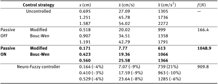
Table 2:Peak responses under the time-scaled El-Centro earthquake.
Control strategy x(cm) x˙(cm/s) ¨x(cm/s2) f(N)
Uncontrolled 0.695
1.251 1.587
27.09 45.78 54.02
1305 1736 2272
Ð
Passive OFF
Modified Bouc-Wen
0.518 0.907 1.191
20.02 34.51 42.79
999 1358 1791
166.4
Passive ON
Modified Bouc-Wen
0.171 0.423 0.560
7.77 19.36 25.58
613 1066 1366
1048.9
Neuro-Fuzzy controller 0.164 (−4%)
0.410 (−3%) 0.529 (−6%)
7.07 (−9%) 17.59 (−9%) 23.64 (−8%)
739 (21%) 963 (−10%) 1285 (−6%)
909.8
A new numerical simulation was carried out to ob-tain the response of the three DOF structure using the MR damper in a passive OFF mode (zero voltage/current input) and passive ON mode (maximum value of the operating voltage/current).
The peak responses of the uncontrolled and controlled systems are listed in Table 2. The results show the effective-ness of the proposed fuzzy based controller in reducing the response of the structure. In this case the fuzzy controller outperforms the passive control modes in almost all peak responses (with exception of the 1stfloor acceleration,
al-though with a significant reduction compared with the un-controlled case).
4
Conclusions
Comparing the controlled responses to those obtained in the uncontrolled and passive control systems, it was ob-served that both passive and semi-active control systems are effective in reducing the seismic responses. However, the semi-active controller allows a more efficient manage-ment of the control forces with a better performance in reducing the structural response. It was also verified that larger damping forces do not always produce better results (e.g., control forces achieved with the passive ON mode are larger than those obtained with the semi-active controller). It can be concluded that the proposed semi-active strategy is an efficient control approach outperforming the passive control modes.
References
[1] Jang J.R., ANFIS: Adaptive-network-based fuzzy inference sys-tem, IEEE Trans. Syst. Man. Cybern., 1993, 23(3), 665-685 [2] Sadeghian A.R., Nonlinear Neuro-Fuzzy Prediction:
Method-ology, Design and Applications, In: Proceedings of the 10th
IEEE International Conference on Fuzzy Systems (2-5 December 2001, Melbourne, Australia), The Institute of Electrical and Elec-tronic Engineers Inc., 2001, 1022-1026
[3] Dyke S.J., Spencer B.F., A comparison of semi-active control strategies for the MR damper, In: IIS ’97 Proceedings of the 1997 IASTED International Conference, Intelligent information Sys-tems (8-10 December 1997, Grand Bahama Island, Bahamas), IEEE Computer Society Washington, 1997, 580-584
[4] Jansen L.M., Dyke S.J., Semi-active control strategies for MR dampers: comparative study, J. Eng. Mech., 2000, 126(8), 795-803
[5] Braz-Cesar M., Barros R., Experimental and numerical analysis of MR dampers, In: COMPDYN 2013 Proceedings of the 4th

![Table 1: Modified Bouc-Wen model - Parameters of the RD-1005-3 MR damper [5]. F = c 1 y˙ + k 1 ( x − x 0 ) y˙ = 1 c 0 + c 1 [ αs + c 0 x˙ + k 0 ( x − y )] s˙ = −β | x˙ | z | z | n−1 − γ x˙ | z | n δ x˙ Current independent δ [-] β [mm 2 ] γ [mm 2 ] k 0 [N/m](https://thumb-eu.123doks.com/thumbv2/123dok_br/16984694.763197/4.892.76.726.129.468/table-modified-bouc-model-parameters-damper-current-independent.webp)