Fl ex ur al o ut -o f-p la ne re tr of itt in g of m as on ry w al ls in h is to ric al c on st ru
Fl
exur
al
out
-
of
-
pl
ane
r
et
r
of
i
t
t
i
ng
of
masonr
y
wal
l
s
i
n
hi
st
or
i
cal
cons
t
r
uct
i
ons
Ba rn a Cs ika i
Ba
r
n
a
Cs
i
k
a
i
Title of the Msc Dissertation:
Flexural out-of-plane retrofitting of masonry walls in historical constructions
Supervisor: Professor Luís F. Ramos
Year: 2013
I hereby declare that all information in this document has been obtained and presented in accordance with academic rules and ethical conduct. I also declare that, as required by these rules and conduct, I have fully cited and referenced all material and results that are not original to this work.
I hereby declare that the MSc Consortium responsible for the Advanced Masters in Structural Analysis of Monuments and Historical Constructions is allowed to store and make available electronically the present MSc Dissertation.
University: Universidade do Minho
Date: 08.07.2013
Signature:
Erasmus Mundus Programme ii ADVANCED MASTERS IN STRUCTURAL ANALYSIS OF MONUMENTS AND HISTORICAL CONSTRUCTIONS
Erasmus Mundus Programme iv ADVANCED MASTERS IN STRUCTURAL ANALYSIS OF MONUMENTS AND HISTORICAL CONSTRUCTIONS
My sincere thanks the Polytechnic University of Catalonia (UPC) for hosting me in the semester of coursework. Especially to Pere Roca Fabregat and Lúca Pelá professors, for believing in me, and for highly contributing to my development with their expertise and kindness.
Thank you for the Consortium for granting me with a scholarship.
I would never forget the great support of Professor István Sajtos, who kept being enthusiastic about my attendance in the SAHC program, giving me great motivation. Many thanks to all of my classmates, for the quality teamwork and for all the fun that we had together in such short time.
I cannot find words to express my gratitude to my loving family for supporting me in every possible way. Thank you very much for everything.
Erasmus Mundus Programme vi ADVANCED MASTERS IN STRUCTURAL ANALYSIS OF MONUMENTS AND HISTORICAL CONSTRUCTIONS
This work aims to develop a reinforcing technique for the flexural strengthening of heritage masonry walls. Extending the idea of an existent technique, adding an enhanced constituent for anchoring, the method comprises an irregular grid that follows the joint texture of the wall. The insertion procedure is much alike a shallow repointing. As a result the technique upgrades the mechanical performance against out-of-plane actions (flexural) and increases the integrity of a structure, without causing visual impact.
Applicability and workability issues remained key aspects of the investigation, which involved experimental and analytical studies. The constituents of the technique were tested individually. Based on the gathered information and on the analytical investigation, monotonic bending tests were prepared finally. The results proved the adequacy of the new technique and allowed decisions on future development. Improvement of anchors and pre-stressing the grid is necessary. For future numerical modeling, the bond behavior of the improved anchors needs to be tested in both axial and transversal direction.
Finally a case study was presented with the discussion of the theoretical application of the new technique on the Alcáçova wall in Guimarães Castle, Portugal. The study showed the practical limits of the technique given by the geometrical constraints of the joint texture of the wall. It also demonstrated that the design abacus – proposed in the analytical investigation – is a powerful tool to define the failure modes and resistance of a strengthened construction.
Conclusions were made on the future development of the technique, giving ideas about the protection of the reinforcement, the improvement of the anchors, alternative materials for the reinforcing grid, and necessary experiments to gather information for numerical modeling.
Erasmus Mundus Programme viii ADVANCED MASTERS IN STRUCTURAL ANALYSIS OF MONUMENTS AND HISTORICAL CONSTRUCTIONS
alvenaria, aplicáveis quer no interior, quer no exterior das paredes. Contudo, a sua aplicação a paredes de alvenaria sem revestimento – o caso da generalidade das ruínas – é muito limitada, dado que a maioria das técnicas introduz impactos visuais incompatíveis com este tipo de construções históricas.
Esta tese visa o desenvolvimento de uma técnica de reforço à flexão para paredes de construções com valor patrimonial elevado tendo em conta a mínima intrusividade na construção. Trata-se de um melhoramento de uma técnica existente através da introdução de elementos que melhoram a ancoragem do reforço nas paredes de alvenaria. Concretamente, o método de reforço consiste na introdução de uma armadura flexível e irregular que consegue acompanhar a geometria das juntas das paredes de alvenaria, podendo ser posteriormente escondida nas juntas de argamassa. Como resultado, a técnica aumenta a capacidade de carga a esforços de flexão para fora do plano das paredes e aumenta a integridade estrutural sem causar impacto visual.
Os pontos fortes desta investigação foram a análise da aplicabilidade e trabalhabilidade desta técnica a construções históricas, em comparação com o melhoramento do seu desempenho estrutural. Após uma análise analítica da aplicabilidade da técnica, foram escolhidos e testados todos os componentes do sistema, culminando numa campanha experimental que incluiu ensaios à flexão em paredes reforçadas à escala reduzida. Os resultados obtidos comprovam a adequabilidade da técnica e apontam alguns melhoramentos necessários para o sistema de reforço ser mais eficiente.
É também apresentado um caso de estudo sobre a aplicabilidade do sistema de reforço na parede da Alcáçova (em ruina) no Castelo de Guimarães. O caso de estudo demonstrou os limites da aplicabilidade da técnica e permitiu aferir aspetos práticos e de dimensionamento, através da análise da geometria da parede e do recurso a um ábaco de dimensionamento desenvolvido para o efeito, prospectivamente.
Finalmente foram apontadas algumas recomendações para futuros desenvolvimentos da técnica, nomeadamente relacionados com a proteção das armaduras, o melhoramento do sistema de ancoragem, materiais alternativos para o reforço e ensaios necessários para realizar análises numéricas do sistema.
Erasmus Mundus Programme x ADVANCED MASTERS IN STRUCTURAL ANALYSIS OF MONUMENTS AND HISTORICAL CONSTRUCTIONS
következtetést engedte levonni, hogy a technikák többsége nehezen, vagy egyáltalán nem alkalmazható vakolatlan történeti szerkezetek megerősítésére, az okozott vizuális elváltozások miatt.
A dolgozat célja egy új, hajlításra történő erősítési technológia kifejlesztése volt történeti falazatok számára. Egy meglévő módszer elméletének kiterjesztésével, valamint egy egyedi fejlesztésű lehorgonyzó elem alkalmazásával, az új rendszer egy a falazat hézagstruktúráját követő, szabálytalan hálóból áll. E háló elhelyezéséhez szükséges a habarcshézagok külső 2-3 cm-ének eltávolítása, majd pótlása a műveletek végeztével. Eredményképpen, a rendszer fejleszti a szerkezet hajlításokra történő működését, valamint fokozza a falazat integritását anélkül, hogy közben károsan érintené annak vizuális megjelenését.
Az alkalmazhatóság és az egyszerű megmunkálhatóság kérdései kulcsszerepet játszottak a kutatás során, mely különböző kísérleteket, és analitikai tanulmányozást is magába foglalt. Végül lehetőség volt hajlítási tesztek elvégzésére is, 1:2 arányú falazott kőfalak alkalmazásával, valamint az új rendszer kipróbálásával. Az eredmények amellett, hogy igazolták a technológia alkalmazhatóságát, segítettek új fejlesztési irányok kijelölésében is a kutatás további folytatásához: Az egyedi lehorgonyzó elemek továbbfejlesztése, valamint előfeszítési eljárás kifejlesztése szükséges. Továbbá szükséges az egyedi kapcsolóelemek lehorgonyzási viselkedésének kiterjedt kísérleti és elméleti jellemzése ‒ tengely, valamint tengelyre merőleges irányban ‒, esetlegesen numerikus modellezéshez is.
Végül egy esettanulmány keretein beül került sor az új rendszer alkalmazhatósági kérdéseinek elméleti tárgyalására. A megerősítendő szerkezet a Guimaraes-i Kastély északi fala, az Alcáçova fal volt, Portugáliában. A tanulmány bemutatja az alkalmazhatósági korlátokat, valamint demonstrálja a tervezési segédlet használhatóságát a különböző tönkremeneteli módok, valamint a teljes ellenállási görbe meghatározásában (a tervezési segédlet létrehozása az analitikai tanulmány részét képezte).
A végértékelés magába foglalta a további fejlesztési irányok következő kérdéseit: Erősítő kábelek fokozott védelme; lehorgonyzó elemek fejlesztése; előfeszítés; alternatív háló
Erasmus Mundus Programme xii ADVANCED MASTERS IN STRUCTURAL ANALYSIS OF MONUMENTS AND HISTORICAL CONSTRUCTIONS
1.3 Thesis outline ... 9
2 Strengthening of Historic masonry walls ... 11
2.1 Structural safety of historical stone masonry walls ... 12
2.2 Existing techniques for the improvement of flexural capacity ... 13
2.2.1 Internal anchoring with post-tensioning tendons ... 13
2.2.2 Near surface mounted reinforcement ... 15
2.2.3 Jacketing and strengthening covers ... 16
2.2.4 External bonded / mechanically fixed materials ... 16
2.2.5 Reticulatus... 17
2.3 Eurocode recommendations ... 18
2.3.1 Characteristic Flexural Strength ... 18
2.3.2 Unreinforced masonry walls subjected to lateral loading ... 19
2.3.3 Characteristic anchorage strength of reinforcement: ... 20
2.3.4 Verification of reinforced masonry members subjected to bending and / or axial loading ... 20
2.4 Further recommendations ... 22
2.4.1 Mechanical parameters of masonry types ... 22
2.4.2 Non-linear kinematic approach ... 23
2.5 Experimental testing of masonry... 25
2.6 Conclusions: ... 28
3 Proposal for Strengthening Technology ... 29
3.1 General description of system ... 30
3.2 Constituents of system ... 32
Erasmus Mundus Programme 2 ADVANCED MASTERS IN STRUCTURAL ANALYSIS OF MONUMENTS AND HISTORICAL CONSTRUCTIONS
4.3 Pull-out test of helibars ... 45
5 Analytical investigation ... 53
5.1 Cost efficiency estimation ... 54
5.2 Practical range of strengthening ... 56
5.3 Design abacus ... 58
6 Scaled masonry wall tests... 63
6.1 Specimens and test procedure ... 64
6.2 Workability issues of strengthening technique: ... 65
6.3 Test setup: ... 68
6.4 Results: ... 69
6.5 Remarks:... 78
7 Case study: Guimarães Castle ... 79
7.1 Brief history of Guimarães Castle ... 80
7.2 The Alcáçova wall ... 80
7.3 Proposal for alternative strengthening... 83
7.4 Strengthening with stainless steel wire ropes ... 84
7.5 Remarks ... 87
8 Conclusions... 89
8.1 Final evaluation of research ... 90
8.2 Ideas for further development ... 90
Figure 5: Internal anchoring applied on irregular stone masonry wall ... 14
Figure 6: Internal anchors applied to irregular stone masonry wall supplemented by a load distributing tie beam ... 15
Figure 7: Sketch of NSM technique applied to irregular stone masonry wall ... 15
Figure 8: Jacketing technique applied on irregular stone wall ... 16
Figure 9: External bond materials applied on irregular stone wall increasing flexural capacity ... 17
Figure 10: “Reticulatus” technique applied for flexural strengthening: frontage and cross-section ... 17
Figure 11: Reticulatus: (a) Ultra High Tensile Strength Steel (UHTTS) cords; (b) Ultra High Molecular Weight Polyethylene (UHMWPE) cords (Borri, et al., 2011). ... 18
Figure 12: a) plane of failure parallel to bed joints; fxk1 b) plane of failure perpendicular to bed joints; fxk2 (Eurocode-6, 2005) ... 19
Figure 13: Stress and strain distribution. Cross section (1) strains (2) internal forces (3) 20 Figure 14: Examples of first-mode “local” damage mechanisms (a) (D’Ayala & Speranza, 2003), and global response mechanism (b). ... 23
Figure 15: Application of the kinematic method, and the linear capacity curve ... 24
Figure 16: Typical examples of masonry test specimens meeting the requirements of Table 5Table 5: Specimen sizes for testing the flexural strength of masonry (EN-1052-2, 1999) ... 26
Figure 17: Implementation of “reticulatus” as flexural strengthening technique ... 30
Figure 18: cleaning of joints with hammer driller ... 30
Figure 19: Synthetic and wire ropes passing in the joints ... 31
Figure 20: Final form of helihead with rounded edges ... 32
Figure 21: Prototypes of heli-needles: rounded head evolution (a) and original sharp edged head (b). Rectangular cross-section of a φ8 helibar (c) ... 32
Figure 22: The connection of prototype hammerhead to the anchoring helibars. ... 33
Figure 23: Insertion of helibar with the application of drillhead prototype ... 33
Figure 24: Stainless steel wire grid applied in masonry joints ... 34
Figure 25: Single sleeve connection type / CA4 (a); Double sleeve connection type / CA2-CA4 (b) ... 36
Erasmus Mundus Programme 4 ADVANCED MASTERS IN STRUCTURAL ANALYSIS OF MONUMENTS AND HISTORICAL CONSTRUCTIONS
Figure 28: Stress – Strain diagram of wire rope tensile test ... 38
Figure 29: Synthetic rope with carbon fibre core (SRCC-2) ... 39
Figure 30: Flexible, high strength mooring synthetic rope ... 40
Figure 31: Procedure of knotting the special connection type ... 41
Figure 32: Force-Extension diagrams of synthetic rope tests ... 41
Figure 33: limit of dry connections related to the theoretical capacity ... 42
Figure 34: Test apparatus of SRCC experiment ... 43
Figure 35: Failure types of SRCC around the clamps; failure in curving part (a); failure at sharp edge (b) ... 43
Figure 36: Test set up of MSR ... 44
Figure 37: Failed connection ... 44
Figure 38: Representation of high deformations of MS / test of specimen n°3 ... 44
Figure 39: Preparation of specimens: insertion of helibars by hammering ... 46
Figure 40: Representative helibar prepared for pullout test ... 46
Figure 41: Connection of gripping plates and LVDT-s to the specimen ... 47
Figure 42: Final test setup with detailing ... 47
Figure 43: Comparison of Force-Displacement envelopes for 8φ8 anchors with two different predrilled holes ... 48
Figure 44: Comparison of Force-Displacement envelopes for 8φ10 anchors with two different predrilled holes ... 49
Figure 45: Comparison of Force-Displacement envelopes for 12φ8 anchors with two different predrilled holes ... 49
Figure 46: Comparison of Force-Displacement envelopes for 12φ10 anchors with two different predrilled holes ... 50
Figure 47: Comparison of Force-Displacement envelopes for 20φ8 anchors with two different predrilled holes ... 50
Figure 48: Comparison of Force-Displacement envelopes for 20φ10 anchors with two different predrilled holes ... 51
Figure 49: Interrelation between mean anchorage forces and anchorage length ... 52
Figure 50: Diagram of the amount of strengthening force that can be utilized from one kilogram of the compared reinforcing materials [kN/kg] ... 54
Figure 51: Costs of materials related to 100 kN of strengthening ... 55
Figure 52: Range of applicability ... 57
Figure 53: Geometrical features; and material laws: for masonry (a), and for wire ropes /synthetic ropes (b) ... 58
Figure 54: n-m interaction curve of different failure modes; Corresponding thickness of wall is small (h=32 cm) ... 60
Figure 55: n-m interaction curve of different failure modes; Corresponding thickness of wall is significant (h=100 cm) ... 61
Figure 56: n-m interaction curve for different amount of strengthening (h=32 cm) ... 62
Figure 67: Rocking failure mode of URW2 ... 71
Figure 68: Applied force-curvature diagram of URW.1 for the definition of cracking .... 72
Figure 69: Prior cracks on URW2 ... 72
Figure 70: Force-deflection diagram of unreinforced walls ... 72
Figure 71: Cracked state of StRW.1 ... 73
Figure 72: Rocking failure mode of StRW.1 with φ4 wire ropes ... 73
Figure 73: Cracked state of StRW.2 ... 74
Figure 74: Rocking failure mode of StRW.2 with φ2 wire ropes ... 74
Figure 75: Cracked state of StRW.3 ... 75
Figure 76: Rocking failure mode of StRW.3 with φ2 wire ropes ... 75
Figure 77: Force-deflection diagrams of reinforced walls ... 76
Figure 78: comparison of effects presented by experiments with the theoretical resistance in design abacus ... 77
Figure 79: site plan of Guimarães Castle; localization of Alcáçova wall ... 80
Figure 80: Global mechanism of Alcáçova wall (Fernández, 2012) ... 81
Figure 81: Front view and cross-section of strengthening Alcáçova wall ... 82
Figure 82: Plan of strengthening Alcáçova wall ... 82
Figure 83: Joint texture of Alcáçova wall (Fernández, 2012) ... 83
Figure 84: Leaf configuration of Alcáçova wall (Moreira, 2010) ... 83
Figure 85: Geometrics of overturning mechanisms: un-strengthened (a) and strengthened wall (b) ... 84
Figure 86: Reduced moment,-axial force interaction curve for Alcáçova wall (σmc=2 MPa) ... 86
Erasmus Mundus Programme 6 ADVANCED MASTERS IN STRUCTURAL ANALYSIS OF MONUMENTS AND HISTORICAL CONSTRUCTIONS
LIST OF TABLES:
Table 1: Values of fxk1, for plane of failure parallel to bed joints (Eurocode-6, 2005) ... 19
Table 2: Characteristic anchorage strength of reinforcement in mortar or concrete not confined within masonry units (Eurocode-6, 2005) ... 20
Table 3: Reference values of the mechanical parameters and average specific weights for selected types of masonry (extracted from Table C8A.2.2. of Circ. NTC08, 2009). Note: fm=compression strength; τo=shear strength; E=Young modulus; G=Shear modulus; W=average specific weight ... 22
Table 4: Mechanical characteristics of stone masonry determined by various authors; Note: E= Elastic modulus; G= Shear modulus; fm= compression strength; ft= tensile strength; τu= shear strength; ν= Poisson’s ration; εu= ultimate strain ... 23
Table 5: Specimen sizes for testing the flexural strength of masonry (EN-1052-2, 1999) 27 Table 6: test matrix for cable tests ... 36
Table 7: Mechanical properties of cables ... 38
Table 8: Physical parameters of SRCC test-specimen types ... 39
Table 9: Test characteristics for rope test ... 40
Table 10: Overview of specimens for pull-out tests ... 45
Table 11: Corresponding bond forces of anchors ... 51
Table 12: Comparison of reinforcing materials; Introduction of applicabe strength/weight ratio ... 54
Table 13: Bending test results ... 69
Table 14: Capacity results of numerical study (Fernández, 2012) ... 81
Table 15: Mechanical properties of constituents ... 84
Table 16: Efficiency of practical maximum reinforcement ... 84
Table 17: Safety evaluation of un-strengthened wall part ... 85
1
INTRODUCTION
Erasmus Mundus Programme 8 ADVANCED MASTERS IN STRUCTURAL ANALYSIS OF MONUMENTS AND HISTORICAL CONSTRUCTIONS
1.1 Motivation
Historic ruins - vacant buildings without floors and roofs; parts of ancient walls; partially destroyed castle walls or archaeological sites - representing high heritage value are unlike the current masonry buildings. These buildings are often only supported in their foundations, cantilevering with no connection to any other construction element that would function as bracing. Other types are left without horizontal support between the roof structures and their foundations, acting as thin supported wall beams. These structures are extremely vulnerable to seismic and wind effects, as they can have very low resistance against out-of-plane actions. It is difficult to find a technique, which is especially developed for the structural consolidation of these types of constructions and at the same time does not adversely affect their authenticity (see on Figure 1).
Figure 1: Additional bracing structures visibly damaging the authenticity of ruins in seismic area
Figure 2 shows the ruins of the Castle of Regéc in Hungary.
reasons, developing new strengthening techniques that do not damage the authenticity of these special constructions is a noble challenge.
1.2 Objectives
The cultural, social, historical and economical importance of heritage structures gives support to present thesis work. Its objective is to carry out an investigation to develop a new alternative way of strengthening historic walls against out-of plane actions.
After studying the existing techniques it becomes clear that most of the strengthening methods are not applicable to un-rendered ancient walls, because of their visual impact. Further disadvantages may appear in workability. Present thesis aims to run a series of experimental investigations to mechanically and physically define a new alternative strengthening technique. Workability issues are taken into account, and reduced visual impact is kept as one of the most important factors. Supplementary to the proposal, analytical investigation is prepared to provide design instructions for the application. Finally, theoretical application of the technique is to be discussed on one of the existing important structures.
1.3 Thesis outline
The present thesis is divided in eight chapters with the following structure:
Chapter 1 gives the introduction to the thesis motivation, describes the objectives and presents the document structure.
Chapter 2 consists of a literature review involving the existing techniques of strengthening, code recommendations, and test procedures with a concentration on the out-of-plane capacity of masonry walls. Based on the gathered information and conclusions made by the author, the aim of the chapter is to define the appropriate way of strengthening, taking into account different aspects, such as mechanical improvement, compatibility, aesthetical damage, workability and sustainability.
Erasmus Mundus Programme 10 ADVANCED MASTERS IN STRUCTURAL ANALYSIS OF MONUMENTS AND HISTORICAL CONSTRUCTIONS the general aspects of the system are discussed. Than a detailed description of the comprised elements are given.
In Chapter 4, experimental investigation on individual constituents can be found. The results were used to conclude on the further development of the proposed strengthening technique, and to make the preliminary calculations for the scaled wall tests. The experimental research comprised tensile tests of stainless steel cables, tensile tests of synthetic ropes, and pull-out tests of helibars from mortar cylinders.
Chapter 5 consists of an analytical study, which was prepared to investigate cost efficiency issues, to define reinforcement on wall specimens for bending tests, and to provide an analytical guide for designing the proposed technique for future practice. Chapter 6 consists of the discussion of scaled stone masonry wall bending tests, with and without the application of the proposed strengthening technique. The tests were undertaken after a reduced curing time of 21 days, and conclusions were based on the relation between mechanical performance, applicability and workability issues.
In Chapter 7 a case study of the Alcáçova wall is presented. Practical and analytical investigation on the application of the new technique is presented, together with a literature review about the historical construction.
Chapter 8 involves the conclusions for the evaluation of the research. Ideas for future development are also presented.
2
STRENGTHENING
OF HISTORIC MASONRY WALLS
Introduction:
The following chapter consists of a literature review involving the existing techniques of strengthening, code recommendations, and test procedures with a concentration on the out-of-plane capacity of masonry walls. Based on the gathered information and conclusions made by the author, the aim of the chapter is to define the appropriate way of strengthening, taking into account different aspects, such as mechanical improvement,
Erasmus Mundus Programme 12 ADVANCED MASTERS IN STRUCTURAL ANALYSIS OF MONUMENTS AND HISTORICAL CONSTRUCTIONS
2.1 Structural safety of historical stone masonry walls
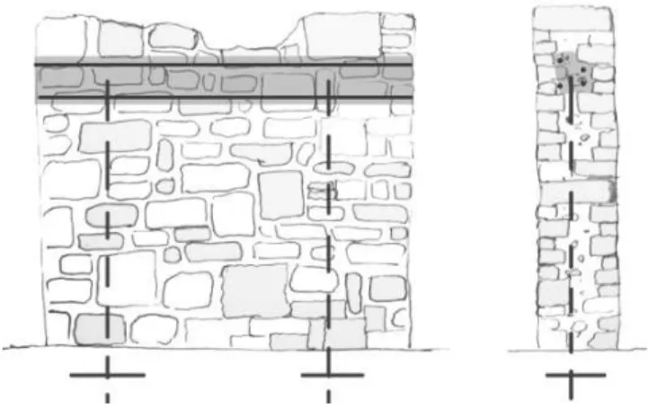
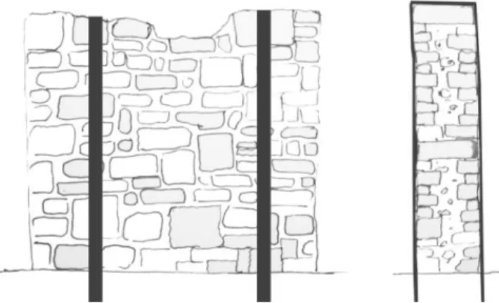
Assessment of the structural safety of historical stone masonry walls is hard, and needs to be done case by case (Binda, et al., 1997; Gelmi, et al., 1993). This problem lies in the peculiar construction type of the walls that is characterized by the: lack of uniformity in geometry; lack of uniformity in material properties; lack of uniformity in cross section (multiple leaf configuration); horizontal and vertical joint texture; shape of units; bond efficiency between units and matrix (see it on Figure 3).
Figure 3: Different shapes of units and different cross-section configuration in stone masonry walls (Binda, et al., 1997).
The most important feature of a stone wall is the bonding of units as it is responsible for the structural integrity of a wall. It is possible to restore and upgrade the integrity of walls with the injection of proper materials into the structure, creating effective bond between units (Binda, et al., 1997; Binda, et al., 1993).
In areas with high seismic risk further strengthening of these structures might be necessary in order to increase the safety level. The global structural role of a wall becomes important. In-plane behaviour of shear walls was discussed in several publications and recommendations for strengthening techniques can be found also in codes (CNR-DT, 200/2004).
Out of-plane deformational capacity of a wall depends on: the boundary conditions and structural integrity of a building; the equilibrium of a rigid body subjected to transversal overturning forces; and transversal flexural capacity of “wall beams” (see representation on Figure 4).
a) b) c) d) Figure 4: Overturning mechanisms of rigid bodies (a,b) and elastic flexural behaviour of wall beams (c,d)
The bearing capacity of masonry walls against out-of-plane actions is very weak compared to their efficiency against in-plane forces. Therefore it is desirable to avoid transversal actions by improving the connections between horizontal and vertical structural elements (floors and walls) and improving the stiffness of floors. By enhancing the global structural (box-) behaviour horizontal forces can be transported to the shear walls and out-of-plane actions can be released. However, in several cases box behaviour is hard or not possible to be activated (Milani, 2013). If more structural integrity cannot be provided, the historical walls need to be strengthened against out-of-plane actions. In this case, increasing flexural capacity and stabilization becomes important.
2.2 Existing techniques for the improvement of flexural capacity
The literature review involved several techniques for the improvement of flexural capacity not only for masonry structures but with the extension to reinforced concrete structures. Advantages-disadvantages, difficulties in application are discussed briefly in the following sections.
2.2.1 Internal anchoring with post-tensioning tendons
Internal anchoring is done by coring through the wall to be strengthened, and applying noncorrosive tendons inside the vertical drill-holes, creating anchorage in the substructure, foundation or soil. A sketch of a strengthened wall can be seen on Figure 5.
Erasmus Mundus Programme 14 ADVANCED MASTERS IN STRUCTURAL ANALYSIS OF MONUMENTS AND HISTORICAL CONSTRUCTIONS
Figure 5: Internal anchoring applied on irregular stone masonry wall
Prestressed tendons with bearing plates are adequate to produce stresses in hinge zones by distributing axial stresses at an angle of 45o in the wall. The flexural capacity of strengthened wall can be estimated with the following formulas (Ismail, et al., 2009).
= + (1)
= + + !" −( & ' )
() * (2)
where:
Mc is the applied moment at crack penetration
Mn is the moment capacity at nominal strength
In is the net moment of inertia of the masonry
c is the distance of extreme compression fibre to neutral axis fr is the modulus of rupture
Pv is the overburden vertical load producing axial compression on the masonry
Psw is the axial load due to self-weight
Aps is the area of pre-stressing steel
fps is the tensile stress in pre-stressing tendons at nominal strength
fse is the effective stress in pre-stressing tendons after all losses
An is the net cross sectional area of the masonry,
deff is the distance of extreme compression fibre to the center of tension reinforcement, λn is a parameter representing the fraction of maximum compressive stress at nominal
strength.
fm is the specified compressive strength of masonry
b is the width of cross section
The technique is not damaging visibly the historical wall, respecting its heritage value, and effectively improves the resistance against out-of-plane actions, such as seismic movement of ground or wind load. Supplementary to the vertical ties, horizontal tie beam can be applied to provide extra integrity by extending the effect of prestressed tendons (see Figure 6).
Figure 6: Internal anchors applied to irregular stone masonry wall supplemented by a load distributing tie beam
2.2.2 Near surface mounted reinforcement
In the developing field of the application of fibre reinforced polymers, the near surface mounted technique is relatively recent, and under testing. It was applied successfully to increase the flexural capacity of concrete and masonry structures (Griffith, et al., 2012; Ismail & Ingham, 2012; Barros, et al., 2008). The reinforcing material is inserted into a small groove on surface, allowing better bond between structure and strengthening. As a consequence the inserted material’s capacity can be utilized more than in case of external bond.
For irregular ancient stone masonry walls the applicability of the technique depends on the type of stone, as grooves need to be cut on surface. The irregular geometry makes it hard to predict the maximum depth of the groove, and although, the technique seems less “invasive” than the external bonded materials - from an aesthetic point of view – the vertical lines of the cuts remain visibly deteriorating, as can be seen on Figure 7.
Erasmus Mundus Programme 16 ADVANCED MASTERS IN STRUCTURAL ANALYSIS OF MONUMENTS AND HISTORICAL CONSTRUCTIONS
2.2.3 Jacketing and strengthening covers
Jacketing is a well-known technique for increasing in-plane capacity of shear walls, and drastically improving the overall performance of walls with low integrity (Churilov & Dumova-Jovanoska, 2013; Papanicolaou, et al., 2011). The technique consists on the application of strengthening layers on both sides of the wall, using reinforcing grids (steel or polymer) and covering mortar (lime, cement, earthen etc.). The layers are also connected through the wall with connector elements, to improve the efficiency. A sketch of the technique can be seen on Figure 8.
Figure 8: Jacketing technique applied on irregular stone wall
Durability problems of embedded steel seem to be overcome by the usage of fibre reinforced polymeric grids and textile meshes, e.g. textile reinforced mortar (Bernat, et al., 2013). New covering systems take advantage of short fibres mixed with a cementitious matrix, such as Strain Hardening Cementitious Composites (SHCC); and Steel Fibre Reinforced Self-Compacting Concrete (SFRSCC). In a recent work (Esmaeeli, et al., 2013) SHCC was successfully applied to masonry beams as flexural strengthening. Related to the present thesis work, the key character of any covering technique is that they cannot be applied to walls that sustain heritage value, because of the invasiveness and visibly damage they cause.
2.2.4 External bonded / mechanically fixed materials
Mechanically fixed steel plates and external bonded FRP materials can be applied as tension members. The strengthening materials are forming vertical or horizontal stripes respecting the purpose of strengthening. In case of irregular, historic stone masonry the technique is questionable; the aesthetic features are not pleasing, material bond is hard issue due to irregularity of geometry (see the representing sketch on Figure 9).
Figure 9: External bond materials applied on irregular stone wall increasing flexural capacity
2.2.5 Reticulatus
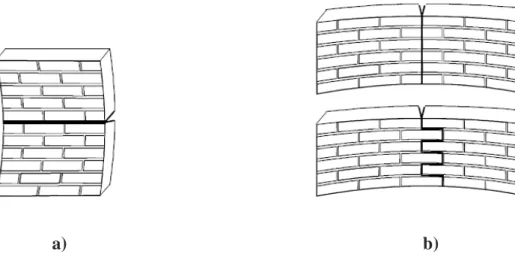
An innovative technique was developed by Borri in Italy (Borri, et al., 2011).
The technique consists of a continuous mesh of steel (or polyethylene) cords, embedded in the repointed mortar joints, the nodes of which are anchored to the wall by means of transversal metal bars, as can be seen on Figure 10 and Figure 11. Alternatively Polyethylene cords were used in the experiment to increase resistibility of mesh.
Strengthened historic wall prisms were subjected to shear tests. Increase of capacity in compression and flexure was also expected, however yet not proved by experimental tests.
Erasmus Mundus Programme 18 ADVANCED MASTERS IN STRUCTURAL ANALYSIS OF MONUMENTS AND HISTORICAL CONSTRUCTIONS
a) b)
Figure 11: Reticulatus: (a) Ultra High Tensile Strength Steel (UHTTS) cords; (b) Ultra High Molecular Weight Polyethylene (UHMWPE) cords (Borri, et al., 2011).
First experimental results showed the new technique’s efficiency, providing better results compared to jacketing with GFRP mesh.
The special external strengthening technique can be applied to irregular stone walls in an aesthetically pleasant way. However, only few experiments were done till now, and the increased labour time appears to be a disadvantage. Further investigation is needed.
2.3 Eurocode recommendations
In the following sections recommendations for basic design concepts of unreinforced and reinforced masonry are collected, concerning flexural capacity and reinforcing details.
2.3.1 Characteristic Flexural Strength
In Eurocode 6 general recommendations can be found for the evaluation of flexural capacity of un-strengthened masonry walls (Eurocode-6, 2005). Two types of failure planes are mentioned with respect to their position related to the bed joints (see on Figure 12).
a) b)
Figure 12: a) plane of failure parallel to bed joints; fxk1 b) plane of failure perpendicular to bed joints; fxk2
(Eurocode-6, 2005)
The characteristic flexural strength of the wall depends on the direction of the flexural plane, fxk1 and fxk2, (Figure 12). For the evaluation of characteristic flexural strength
Eurocode 6 recommends values for the mortar strength and the flexural strength of individual units (see Table 1). However, in the case of historical, irregular stone masonry walls it is advisable to obtain the values by experimental tests, as it is cited from Eurocode 6.
Table 1: Values of fxk1, for plane of failure parallel to bed joints (Eurocode-6, 2005)
Masonry Unit
fxk1 (N/mm2)
General purpose mortar
Thin layer mortar Lightweight mortar fm< 5 N/mm2 fm > 5 N/mm2
Clay 0,10 0,10 0,15 0,10
Calcium silicate 0,05 0,10 0,20 not used
Aggregate concrete 0,05 0,10 0,20 not used
Autoclaved concrete 0,05 0,10 0,15 0,10
Manufactured stone 0,05 0,10 not used not used
Dimensioned natural stone 0,05 0,10 0,15 not used
2.3.2 Unreinforced masonry walls subjected to lateral loading
At the ultimate limit state, the design value of the moment applied to the masonry wall,
MEd (see EC6 Section 5.5.5), shall be less than or equal to the design value of the moment
of resistance of the wall, MRd, such that:
+, ≤ ., (3)
Erasmus Mundus Programme 20 ADVANCED MASTERS IN STRUCTURAL ANALYSIS OF MONUMENTS AND HISTORICAL CONSTRUCTIONS
., = /,× 1 (4)
where:
fxd is the design flexural strength appropriate to the plane of bending, Z is the elastic section modulus of unit height or length of the wall.
2.3.3 Characteristic anchorage strength of reinforcement:
The characteristic anchorage strength of reinforcement bedded in mortar or concrete shall be obtained from the results of tests. Recommendations can be found for the evaluation of regular reinforcing steel bars bedded in concrete or mortar.
Table 2 can be used for comparison between test results using special anchorage elements (addressed by present work) and code recommendations for using regular steel bars.
Table 2: Characteristic anchorage strength of reinforcement in mortar or concrete not confined within masonry units (Eurocode-6, 2005)
Strength class of
Mortar M2-5 M5-9 M10-14 M15-19 M20
Concrete not
used C12/15 C16/20 C20/25 C25/30 <
fbok for plain carbon steel bars (N/mm 2
) 0,5 0,7 1,2 1,4 1,4
fbok for high-bond carbon steel and
stainless steel bars (N/mm2) 0,5 1,0 1,5 2,0 3,4
2.3.4 Verification of reinforced masonry members subjected to bending and / or axial loading
Externally reinforced masonry subjected to bending can be calculated using the same theory as for the calculation of reinforced concrete bended elements (EC6- Section 6.6.2), as can be seen in Figure 13.
where:
b is the width of the section;
d is the effective depth of the section;
As is the cross-sectional area of the reinforcement in tension;
fd is the design compressive strength of masonry in the direction of loading
fyd is the design strength of reinforcing steel.
Additional information can be found for the special case of reinforced masonry cantilever walls subjected to bending.
To calculate the moment of resistance, MRd, , the design compressive strength, fd, in
Figure 13, may be taken over the depth from the compressed edge of the cross-section, λx, when the design value of the moment of resistance, MRd, in compression, should not be
taken to be greater than:
<" = 0.4 × " × > × " for Group 1 units other than lightweight aggregate units (EC6- equation 6.24a) (7) and
<" = 0.3 × " × > × " for Group 2, 3 and 4 and Group 1 lightweight aggregate units. (EC6- equation 6.24b) (8) where:
b is the width of the section;
d is the effective depth of the section;
fd is the design compressive strength of masonry; x is the depth to the neutral axis.
Erasmus Mundus Programme 22 ADVANCED MASTERS IN STRUCTURAL ANALYSIS OF MONUMENTS AND HISTORICAL CONSTRUCTIONS
2.4 Further recommendations
Italian and other recommendations were reviewed for the better understanding of the mechanical behaviour of historical masonry.
2.4.1 Mechanical parameters of masonry types
Magenes and Penna proposed a table (herein Table 3) for the evaluation of mechanical parameters of different masonry types (Magenes & Penna, 2009). After the in-situ recognition of typology and quality of materials, the table can be used to associate the results with other mechanical properties. The table is compiled on the basis of the experimental data obtained and collected by the authors. However, no information was found about the leaf configuration of reference structures.
Table 3: Reference values of the mechanical parameters and average specific weights for selected types of masonry (extracted from Table C8A.2.2. of Circ. NTC08, 2009). Note: fm=compression strength; τo=shear
strength; E=Young modulus; G=Shear modulus; W=average specific weight
Masonry typology fm (N/mm2) τo (N/mm2) E (N/mm2) G (N/mm2) W (kN/m3)
min-max min-max min-max min-max
Irregular stone masonry (pebbles, erratic, irregular stone)
1,0 1,8 0,020 0,032 690 1050 230 350 19
Uncut stone masonry with facing walls of limited thickness
and infill core
2,0 3,0 0,035 0,051 1020 1440 340 480 20
Cut stone with good bonding 2,6 3,8 0,056 0,074 1500 1980 500 660 21
Soft stone masonry (tuff, limestone, etc.) 1,4 2,4 0,028 0,042 900 1260 300 420 16
Dressed rectangular (ashlar) stone masonry 6,0 8,0 0,090 0,120 2400 3200 780 940 22
Soli brick masonry with lime mortar 2,4 4,0 0,060 0,090 1200 1800 400 600 18
The parameters are varying and rather low compared to other experimental investigations. An overview of experimental results is given by different authors with mechanical parameters of one masonry type. The difficulty in determining general parameters for different masonry types becomes understandable after checking the comparison in Table 4.
fm [MPa] – 0.98 5.80 - 15.1 1.500 0.33 - 0.98 3.00 2.26 1.74-2.26 ft [MPa] – 0.60 -1.40 0.09 - 0.14 – 0.02 - 0.32 0.04 - 0.18 – ~0.10 τu [MPa] 0.07 - 0.23 – 0.08-0.09 – – – – – ν – – 0.10 - 0.15 0.250 – – 0.07 - 0.20 – εu – – - <0.003 – – – <0.0016 - 0.0026 Type of
results In-situ Lab. Lab. Lab. In-situ
Ref. of Buildings
Double
flat-jack Lab.
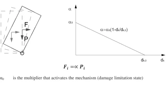
2.4.2 Non-linear kinematic approach
The method stands for the special cases, when the above mentioned box behaviour cannot be activated. In this case the structural performance of a building is defined by the behaviour of local mechanisms (see Figure 14). Based on the equilibrium equation of rigid blocks, the kinematic approach allows the determination of the horizontal action that activates the mechanism (Circolare-C8A). The structure is progressively able to stand with the evolution of the mechanism, until the annulment of the affecting horizontal force, as illustrated in Figure 15.
Erasmus Mundus Programme 24 ADVANCED MASTERS IN STRUCTURAL ANALYSIS OF MONUMENTS AND HISTORICAL CONSTRUCTIONS
@A =∝ CA
α0 is the multiplier that activates the mechanism (damage limitation state)
dk displacement of a suitable control point k of the system (for example the center
of the mass)
dk,0 displacement of a suitable control point k of the system, for which the
multiplier of the horizontal loads is void (α=0)
Figure 15: Application of the kinematic method, and the linear capacity curve
Formulas are available for the safety verification in
- Damage Limit State (DLS): Structural components remain in the elastic range - Ultimate Limit State (ULS): Structural components suffer repairable damage Damage Limit State:
The safety verification with reference to the DLS is satisfied when the spectral acceleration for the activation of the mechanism a*0 is greater than the acceleration of the
elastic spectrum, defined in the point 3.2.6 of the ordinance
DE∗ ≥ HIJ&,L (1 + 1,5NM) (9)
where:
Z is the height of the centre of the masses that generate horizontal forces on the elements of the kinematic chain, because they are not effectively transmitted to other parts of the buildings,
H is the height of the whole structure
In case of local mechanisms, the damage limitation state corresponds to the arising of cracking that interests not the whole but only a part of the structure.
where:
Z is the height of the centre of the masses that generate horizontal forces on the elements of the kinematic chain, because they are not effectively transmitted to other parts of the buildings,
H is the height of the whole structure,
q is the structure factor assumed equivalent to 2.
b) Verification through capacity spectrum (non-linear kinematic analysis): The corresponding formulas can be found in the ordinance chapter C8A 4.2
2.5 Experimental testing of masonry
Recommendations for four-point-bending test of masonry were found in Eurocode (EN-1052-2, 1999). The tests are recommended to be performed vertically. The configuration can be seen in Figure 16 and dimensional details of the specimens can be read in Table 5.
Explanations of signs are listed here:
fxd is the flexural strength of an individual masonry specimen, (N/mm 2
) fmean is the mean flexural strength of the masonry specimens, (N/mm
2
) fxk is the characteristic flexural strength of masonry, (N/mm
2
) hu is the height of masonry unit, (mm)
k is the numerical factor
ls is the length of a masonry specimen in the direction of span, (mm)
lu is the length of masonry unit, (mm)
l1 is the spacing of the outer bearings, (mm)
l2 is the spacing of the inner bearings, (mm)
n is the number of specimens
s is the standard deviation of the log values tu is width of masonry unit (mm)
Erasmus Mundus Programme 26 ADVANCED MASTERS IN STRUCTURAL ANALYSIS OF MONUMENTS AND HISTORICAL CONSTRUCTIONS Configuration of test and dimensions of specimens:
a) Flexural strength for a plane of failure parallel to the bed joints
b≈2lu and b≥ 400 mm and hu≤ 250 mm and more
than two bed joints in l2
b) Flexural strength for a plane of failure perpendicular to the bed joints
b≈4hu and b≥ 240 mm and hu≤ 250 mm and a
minimum of one head joint in l2
a) Flexural strength for a plane of failure parallel to the bed joints
b≈2lu and b≥ 400 mm and hu≤ 250 mm and more
than two bed joints in l2
b) Flexural strength for a plane of failure perpendicular to the bed joints
b≈4hu and b≥ 240 mm and hu≤ 250 mm and a
minimum of one head joint in l2
Loading:
Increasing the flexural stress at a rate between 0,03 N/mm2/min and 0,30 N/mm2/min is advisable.
Construction and the curing of the specimens:
Construction of a specimen should not be later than 30 minutes after the conditioning of units. Curing of specimens should be 28 ± 1 day before testing. For lime-based mortars an alternative curing regime and period may be necessary, and this should be specified. Tests shall take place at same age.
Calculation:
The formula for the calculation of flexural strength of each un-strengthened specimen:
/R = STU,VWX(YZ[Y\&:]^\ ) _/aa& (11)
where:
fxi is the flexural strength of the unstrengthened specimen
Fi is the load
l1 is the spacing of the outer bearings, (mm)
l2 is the spacing of the inner bearings, (mm)
b is width of masonry wall specimen tu is width of masonry unit (mm)
Erasmus Mundus Programme 28 ADVANCED MASTERS IN STRUCTURAL ANALYSIS OF MONUMENTS AND HISTORICAL CONSTRUCTIONS
2.6
Conclusions:
Starting from a general point of view, the state of art review discussed the problems of irregular stone masonry, with special attention to the out-of-plane behaviour and the improvement of flexural capacity. Existing strengthening techniques were listed in relation to the main topic, with an extension to other materials, such as reinforced concrete. The question of applicability was discussed in terms of aesthetics and safeguarding heritage value. As a conclusion, most of the existing methods are not applicable to un-rendered stone masonry walls, as visibly deteriorating techniques cannot be used (e.g.: jacketing, covering, external bonded materials). The insertion of internal tendons was proved to be adequate, but alternative solutions could be necessary. The “reticulatus” technique advocated by A. Borri can solve the aesthetic problems of external strengthening, by the insertion of an irregular grid into the joints of masonry. However, there is a need for experimental investigation of the application as flexural strengthening. Based on the main advantages of “reticulatus” technique, a new flexural strengthening technique is going to be outlined in present thesis work, applicable to irregular and regular masonry walls bearing heritage value.
3
PROPOSAL FOR
STRENGTHENING TECHNOLOGY
Introduction:
In the following chapter a reinforcing system is proposed with the aim of increasing the out-of-plane bending resistance of stone masonry walls and reducing visual impact on structure. First the general aspects of the system are discussed. Than a detailed description of the comprised elements are given.
Erasmus Mundus Programme 30 ADVANCED MASTERS IN STRUCTURAL ANALYSIS OF MONUMENTS AND HISTORICAL CONSTRUCTIONS
3.1 General description of system
Considering the key aspects of the “reticulatus” (Borri, et al., 2011), an external strengthening technique is proposed for the flexural strengthening of historic masonry. The reinforcement is chosen in a way to be able to follow the joint texture in shallow depth, and to adapt even 90° in intersections of joints (see the sketch of the technique in Figure 17). With appropriate refilling of joints, the reinforcement is hidden, and no visual damage is done on the structure.
Figure 17: Implementation of “reticulatus” as flexural strengthening technique
The system includes the following steps in application
- Removal of the mortar from the joints in a depth of 2 to 3 cm, to be able to embed the reinforcing grid (see it on Figure 18);
Figure 18: cleaning of joints with hammer driller
- Introduction of helical stainless steel needles in masonry cross joints (where horizontal and vertical joints meet). Before the application of needles a pre-drill is made with a diameter smaller than the diameter of the heli-needles, in order to make the insertion easier. Subsequently the connectors are inserted by hammering with a device designed for this purpose;
Figure 19: Synthetic and wire ropes passing in the joints
- The cables / ropes together with the special connectors are creating irregular, distributed armour in the joints. The cables have 2 or 4 mm in diameter, in order to be flexible enough to follow the mortar joints and adapt angles of 90°. The cables should be placed to provide the desired orientation for a better resistance against bending stresses;
- After the application of cables, all joints are repointed with the appropriate mortar, so that the reinforcement system would not be visible.
When the walls - reinforced with this system - are subjected to out-of-plane bending forces, the cables / ropes will work in tension. The adaption of helical rods for anchoring the cables is expected to improve the efficiency.
The main characteristics of this system are:
- cables can be applied on both sides of the wall, so the strengthened structure can resist positive as well as negative bending moments;
- As the reinforcement is placed near surface, the useful height of a bending resistant cross section is quasi equivalent to the thickness of the wall;
- The required works are expected to be simple to perform, equipment is easy to handle, and does not require skilled labour;
- The invasiveness of the technique is superficial and only affecting joints, similarly to a shallow structural repointing.
Erasmus Mundus Programme 32 ADVANCED MASTERS IN STRUCTURAL ANALYSIS OF MONUMENTS AND HISTORICAL CONSTRUCTIONS
3.2 Constituents of system
The head of helibars:
Mortar joints of stone masonry walls can be quite narrow. In case of regular carved stone blocks 2 cm spacing is usual. Hence it is important to optimize the shape of the head of the heli-bars, in order to ensure the possibility of insertion and that it would not exceed the plane of the wall surface after application. A cross shape was designed as it can be seen in Figure 20. The shape was optimized to be rounded to provide easier passing, and more space for cables. The rounded edges are also reducing the probability of damage in wires.
Figure 20: Final form of helihead with rounded edges
The helibars:
The helical connector element (see it on Figure 21) can easily penetrate into the mortar due to its special shape. This attribute has been tested on masonry walls in the Laboratory of Structures at University of Minho. Drill holes with a diameter smaller than the connector element were made previously on the wall, Then the helibar’s were inserted into the drill hole. The bars could penetrate in a rolling way by simple hammering.
Figure 21: Prototypes of heli-needles: rounded head evolution (a) and original sharp edged head (b). Rectangular cross-section of a φ8 helibar (c)
(a)
(b)
head has the shape and dimensions to allow the helibar to be easily inserted and trapped in it (see representation on Figure 22). The hammer head is also adequate for the full insertion of the helibars, allowing the connectors to be hidden in the joints, as you can see it on Figure 23.
Figure 22: The connection of prototype hammerhead to the anchoring helibars.
Erasmus Mundus Programme 34 ADVANCED MASTERS IN STRUCTURAL ANALYSIS OF MONUMENTS AND HISTORICAL CONSTRUCTIONS The structural grid:
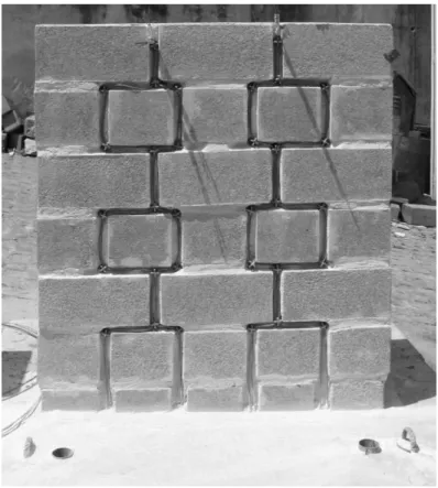
Two types of materials were introduced to form the structural grid in the mortar joints. Stainless steel cables and synthetic ropes can be both applicable in terms of workability. As general recommendation, the wires should be straight lined between two connector elements, in order to be immediately activated when out of plane forces are affecting the target wall. To reach this immediate activation, pre-stressing of the ropes might be necessary. Stainless steel wire grid applied to a test specimen can be seen on Figure 24.
Figure 24: Stainless steel wire grid applied in masonry joints
Starting and finishing connections are playing important role in the efficiency of the method, as forces are expected to be transmitted to the wall there. The bottom connection must be placed lower than the height of the expected plastic hinge. Top connections can be made on both sides of the wall, or – with additional elements for protection on edges – the reinforcement can be passed over the wall and integrate the two sides. The chosen connection types have to be strong enough for load transition. Helibars, injected insertions, or other appropriate connections can satisfy this function.
4
MECHANICAL CHARACTERISATION
OF CONSTITUENT ELEMENTS
Introduction:
In the following chapter, experimental investigation on individual constituents can be found. The results were used to conclude on the further development of the proposed strengthening technique, and to make the preliminary calculations for the scaled wall tests. Tensile tests of stainless steel cables; tensile tests of synthetic ropes; pull-out tests of helibars from mortar cylinders;
Erasmus Mundus Programme 36 ADVANCED MASTERS IN STRUCTURAL ANALYSIS OF MONUMENTS AND HISTORICAL CONSTRUCTIONS
4.1 Direct tensile test of stainless steel wire ropes
In order to characterize the mechanical properties of wire ropes and to evaluate the efficiency of the hand-made connection types, 13 specimens were subjected to tensile test. The main properties that were to be extracted from the experiments were the tensile strength (fy ; fu), corresponding equivalent strains (εy ; εu) and the elastic modulus (E) of
the different cables. During the investigation two series of tests were undertaken related to connection types (single sleeve; doubled sleeves). The results indicated no significant difference between mechanical properties. Therefore the number of aluminium sleeves proved not to influence the strength of any specimen. Figure 25 shows the different connection types, defined by the number of sleeves, and Table 6 lists the specimens for testing.
(a) (b)
Figure 25: Single sleeve connection type / CA4 (a); Double sleeve connection type / CA2-CA4 (b)
Table 6: test matrix for cable tests
Name Diameter [mm] Number of sleeve Number of tests Reference length [cm]
CA2 2 single 3 30,5 CA4 4 single 3 30,5 CA6 6 single 3 37,7-38,3 CA2#2 2 double 2 32-33 CA4#2 4 double 2 34-34,5 Results:
Failure happened in the connections without exception, as it could be expected. The manufacturing of the connection introduces imperfections such as strains and perpendicular confining compression to the fibres, due to deformed sleeves. Such imperfections are creating weak-points determining the localization of failure. However, the breaking forces appeared to be higher than the nominal values for each specimen. As it can be seen in Figure 26 the force-deformation diagrams can be divided into a linear and a non-linear part. The non-linear part allows greater deformations, but is not related
Figure 26: Load-Extension diagram of wire rope tensile tests 0 2000 4000 6000 8000 0 5 10 15 20 L o Extension [mm] CA4_3 CA4#-2 CA4#-3 CA6_1 CA6_2 CA6_3
Erasmus Mundus Programme 38 ADVANCED MASTERS IN STRUCTURAL ANALYSIS OF MONUMENTS AND HISTORICAL CONSTRUCTIONS The mean values of mechanical properties were extracted, and are listed in Table 7. The Young Modulus (E) was taken between the 20% and the 50% of the nominal strength as it is recommended in the ASTM standards for testing wire ropes (A931-96, 2002) . See the corresponding graphs in Figure 28.
Figure 28: Stress – Strain diagram of wire rope tensile test
Table 7: Mechanical properties of cables
Name of specimen
Elastic limit Ultimate limit
E [N/mm2] εs [%] fy [N/mm2] εsu [%] fu [N/mm2] Pu [kN] Nominal Pmax [kN] CA2-CA2#2 53000 1,350 713 2,55 955 3,00 2,24 CA4-CA4#2 44000 1,600 711 3,00 820 10,3 8,94 CA6 22300 2,197 490 4,00 614 17,3 14,0 Remarks:
The tests can be considered as successful despite the failure in connections, since the results appeared to be better than the nominal values, and the graphs are not showing the signs of early failure.
It was revealed that different cables have significantly different mechanical properties. The influence of doubled sleeves on the mechanical properties was also investigated and turned out not to affect the results.
Mechanical behaviour of stainless steel cables has non-linearity, but not due to plasticity.
0 100 200 300 400 500 600 700 800 900 1000 1100 1200 0 1 2 3 4 5 S tr e s s [M p a ] Equivalent strains [%] CA2_1 CA2_2 CA2_3 CA2#-2 CA2#-3 CA4_1 CA4_2 CA4_3 CA4#-2 CA4#-3 CA6_1 CA6_2 CA6_3
The first series of tests were undertaken with Synthetic Ropes with Carbon fibre Core (herein SRCC-2 and SRCC-4 respecting the diameter) designed by the Department of Civil Engineering at the University of Minho. In case of SRCC-2 the uni-direction inside core is made of 4x1600 tex HTS 5631 carbon fibres protected by 20 yarns of weaved polyester - 10 tex (see Figure 29). SRCC-4 contains 12x1600tex HTS 5631 carbon fibre yarns protected by 20 yarns of weaved polyester - 10 tex.
Figure 29: Synthetic rope with carbon fibre core (SRCC-2)
SRCC ropes were designed to be competitive with 4 mm diameter stainless-steel cables in terms of mechanical properties and workability (flexibility and diameter dimension). For experimental investigation SRCC-2 and SRCC-4 specimens were prepared. The reference length of the specimens was set to 100 mm (see physical parameters in Table 8).
Table 8: Physical parameters of SRCC test-specimen types
Name Equivalent diameter [mm] Reference length [mm]
SRCC_2 2 100 mm
SRCC_4 4 100 mm
The vulnerability of carbon fibre core against sharp folding, or small diameter curving was expected to be a great disadvantage in terms of workability. For efficient application, special connections might be needed.
Erasmus Mundus Programme 40 ADVANCED MASTERS IN STRUCTURAL ANALYSIS OF MONUMENTS AND HISTORICAL CONSTRUCTIONS Synthetic ropes used in mooring:
A second series of tests were done with high strength synthetic ropes used mainly in mooring (herein MSR). One specimen can be seen in Figure 30. The polymer chords are weaved to form a strand, which has extremely high strength without the usage of inside core (6 mm diameter 19,8 kN). As a consequence, the rope is more resistant to sharp folding and curving, resulting in a more workable product, leaving the chance of creating simple, handmade connections. Physical characteristics are listed in Table 9.
Figure 30: Flexible, high strength mooring synthetic rope
Table 9: Test characteristics for rope test
Name Equivalent diameter [mm] Reference length [mm]
MSR1 6 212 mm
MSR2 6 120 mm
MSR3 6 90 mm
A special type of knot was tested in connections with the workable material, as it was able to adapt to folding. The use of knots would increase the workability of the technique, as it is simple to do, very fast, and provides good load transition. See the representation on Figure 31.
Experimental results and evaluation
The resultant graphs of the experiments are given in Figure 32.
Figure 32: Force-Extension diagrams of synthetic rope tests 0 1000 2000 3000 4000 5000 6000 7000 8000 9000 0 50 100 150 200 F o rc e [ N ] Extension [%] SRCC_2-1 SRCC_2-2 SRCC_2-3 SRCC_2-4 MSR1 MSR2 MSR3 0 1000 2000 3000 4000 5000 6000 7000 8000 9000 0 50 100 150 200 F o rc e [ N ] Extension [%] SRCC_2-2 MSR3 SRCC_4-1 SRCC_4-2 SRCC_4-3
Erasmus Mundus Programme 42 ADVANCED MASTERS IN STRUCTURAL ANALYSIS OF MONUMENTS AND HISTORICAL CONSTRUCTIONS The dry connections were vulnerable points in each series of tests. Figure 33 represents the obtained failure loads in percentage, related to the theoretical material and composite ultimate loads. Using dry connections, the results were not closing the real strength of the materials. SRCC-2 reached 20% of the theoretical 15,6 kN; and SRCC-4 provided 11.1% of its theoretical 46.38kN capacity. The MSR reached 32,8 % of its theoretical ultimate load (19.8kN). It is worth noting that dry connections need further development in order to use the capacity of these composites more efficiently.
Figure 33: limit of dry connections related to the theoretical capacity
For the proposed application, the SRCC-2 was not proved to be competitive with 4 mm diameter wire ropes, despite its promising theoretical strength (15,6kN). Reaching 3,5 kN as ultimate load, it can be an alternative solution to the usage of 2mm diameter stainless steel cables. The mean stiffness of the composite is 291 N/mm between 30% and 60% of the quasi ultimate load, when the steel cables provide 660 N/mm.
SRCC-4 also provided early failure at 5 kN load during the test compared to its theoretical strength (46.4 kN). The failure was due to the extreme vulnerability of the composite against sharp edges and looping. It can be noted, that increasing the amount of carbon fibre filaments did not provide better results during experimental investigation. The mean value of stiffness was 174,7 N/mm (26,5% of steel cables).
As a conclusion, both SRCC2 and SRCC4 failed to compete with the φ4 wire rope in terms of mechanical efficiency. (Note: Stainless steel wire rope is capable of reaching its ultimate capacity (~11 kN) with dry connections).
The use of special knot with MSR caused early failure during the tests. Additional confinement and transversal strains in connection can significantly reduce the strength of the material. The MSR compared to the SRCC provided very low stiffness results. The extracted mean value is 129 N/mm taking into account the initial quasi-linear part of the graphs. The significant difference can be easily represented by comparing the load values at 20% extension. The SRCC almost reaches its peak load (3-3,5kN), while the MSR is only capable of taking 1 kN (as you can see on Figure 32). Due to the low stiffness, and
20,0%
11,1%
32,8%
SRCC-2 SRCC-4 MSR
Figure 34: Test apparatus of SRCC experiment
(a) (b)
Erasmus Mundus Programme 44 ADVANCED MASTERS IN STRUCTURAL ANALYSIS OF MONUMENTS AND HISTORICAL CONSTRUCTIONS
Figure 36: Test set up of MSR Figure 37: Failed connection