DECOU PLED
SPACE-TIME PROCESSING FOR
EQUALIZATION AND CO-CHANNEL INTERFERENCE
CANCELLATION IN MOBILE COMMUNICATION SYSTEMS
A. L. F. de Almeida, F. R. P. Cavalcanti ,
J.
C. M. Mota, and C. E. R. Fernandes
Abstract In this article we propose a spacetime processing strategy for combined equalization and (cochannel) interference cancellation in mobile communications. The principle of this strategy is to decouple interference cancellation and signal equalization in two processing stages. The socalled decoupled spacetime (DST) processing strategy consists of employing an antenna arrav or a spacetime filter to cancel the cochannel
ゥョエ・イヲ・イセイ
signals in the space domain or in the spacetime domain and an equalizer to perform intersymbol interference suppression in the time domain. This is achieved by optimizing the effective channel impulse response of the user of interest in such a way that the signaltointerferenceplusnoise ratio (SINR) at the input of the equalizer is maximized. In this contribution the optimization criteria for the DST strategy are presented and optimum receiver settings are derived. The biterrorrate (BER) performance of adaptive DST processing structures is evaluated by means of linklevel simulations under the COST 259 channel model. The results show superior performance of the DST receiver structures as compared to conventional approaches.
Keywords: Spacetime processing, equalization, interference cancellation, decoupled
Resumo Neste artigo propomos uma estrategia de processamento espacotemporal para comunicacoes m6veis que combina equalizacao e cancelamento de interferencia cocanal. a principio desta estrategia
e
desacoplar cancelamento de interferencia e equalizacao em dois estagios de processamento. A estrategia de processamento espacotemporal desacoplado (DST) consiste ern utilizar urn arranjo de antenas ou urn filtro espacotemporal para cancelar somente os sinais dos interferentes cocanais no dominio espacial ou espacotemporal e urn equalizador para supressao de interferencia intersimb6lica no dominio temporal. Isto se da atraves da otimizacao da resposta ao impulso efetiva do canal do usuario de interesse , objetivando maximizar a razao sinalinterferenciamaisruido (SINR) na entrada do equalizador. Nesta contribuicao, alguns criterios de otimizacao para a estrategia DST bern como solucoes 6timas sao apresentados. a desempenho, em termos de taxa de erro de bit (BER), de estruturas DST adaptativase
avaliado atraves de simulacoes em nfvel de enlace utilizandose 0Andre Lima. F. de Almeida. Feo. Rodrigo P. Cavalcanti, Joao Cesar M. Mota and Carlos Estevao R. Fernandes are with Grupo de Pesquisa em Telecornunicacoes SemFio (GTEL), Universidade Federaldo Ceara (UFC). (Emails:andre@gtel.ufe.br. rod@gtel.ufe.br, mota@gteLufe.br, estevao@gteLufe.br)
modelo de canal COST 259. as resultados confirmam desempenho superior de estruturas de recepcao DST, quando comparadas as etrategias convencionais.
Palavraschave; Processamento espacotemporal, equalizacao, cancelamento de interferencia, desacoplado
1.
INTRODUCTION
Current mobile communication systems have an increasing demand for user capacity and improved spectral efficiency. As the number of subscriber units at the same frequency channel increases, cochannel interference (CC!) becomes a major limiting factor. Additionally, in highspeed digital mobile communication services intersymbol interference (IS!) due to frequencyselective fading is also a limiting factor that degrades the biterrorrate (BER) performance. Adaptive antenna technology is the classical solution to combat multipath fading effects and CCI [1,2]. An adaptive array (AA) is a spaceonly processing strategy that explores the spatial signature of the incoming signals in order to separate them. The AA can also perform spatial equalization, by nulling out the delayed multipaths of the user of interest [3]. However, in rich multipath scenarios the problem of insufficient spatial degrees of freedom may degrade CCI cancellation. On the other hand, temporal equalization is the classical solution to mitigate lSI. The temporal equalizer (TE) explores the temporal signature of the received signal, i.e. the channel impulse response in order to compensate for channel distortion. The TE can also perform CCI cancellation with oversampling, but noise enhancement degrades performance if the subchannels are correlated [4].
Receiver spacetime processing is characterized by the joint use of spacedomain and timedomain processing, where the spatial and temporal signature of the signals are explored in order to separate them according to some performance criterion. The design of spacetime processing receivers has been the focus of several studies due to its capability to deal with CCI and lSI simultaneously [4]. In typical wireless systems where CCI is unknown at the receiver, optimum spacetime processing could be implemented by a multichannel maximum likelihood sequence estimator (MLSE) for signal detection [5]. However, this receiver is generally too computationally demanding to be implemented and suboptimum schemes should be considered.
Revista da Sociedade Brasileira de Telecornunlcacoes
Volume 18, Nurnero 1, Junho de 2003
AA front end
decisions
,,(k)
r
Figure 1. Cascaded connection of an adaptive array (AA) and a temporal equalizer (TE).
v(k) decisions
Figure 2. Linear spacetime filter (STF) for simultaneous CCI and lSI suppression.
for CCI cancellation and spatial lSI suppression. The TE can follow either an MMSE or an MLSE criterion in order to suppress residual lSI at the output of the array,
Simultaneous CCI and lSI mitigation can be achieved with a linear spacetime filter (STF), where a tapdelayline filter is employed at each branch of the AA [4, 7J(Fig. 2). The STF combines the input signal in space and time and seek to minimize the error between the output signal and a desired signal. Unlike the AA, the STF can explore the temporal diversity of the CCI signals in order to suppress them. One can also combine the STF with a nonlinear equalizer to
enhance lSI suppression.
All these strategies and its variants exhibit advantages and drawbacks in terms of performance and cost of implementation. In terms of performance, the selection of a given spacetime processing algorithm or receiver configuration will depend on whether the propagation channel is more CCI or lSIlimited [3]. Thus, we can say that the algorithm performance depends on the joint design of the frontend (AA or STF) and the equalizer. On the other hand, algorithm complexity is generally dictated by the TE, e.g. the number of trellis states in the MLSE.
セcッョ」・イョゥョァ
lSI and CCI suppression it is desirable that
the AA or the STF utilizes all its degrees of freedom to minimize CCI only (and eventually the tail of the lSI) while a subsequent TE should perform lSI suppression. However, in rich multi path scenarios with strong CCI signals and lSI the performance of spacetime processing receivers can be severely degraded. Considering an adaptive AA cascaded with an MLSE equalizer (AAMLSE), insufficient degrees of freedom causes poor CCI cancellation and the presence of residual CCI at the equalizer input degrades the overall BER performance. The presence of spatially correlated multipath from the desired user also decrease the output SINR complicating the task of the TE that may not be able to compensate for this loss of SINR [12]. The aforementioned problems can be minimized by treating CCI and lSI separately in two processing stages. This idea was applied in previous works with different approaches [8l5J and has been called decoupled spacetime (DST) processing. In this work we propose a unified approach for the separation of CCI and lSI treatment with spacetime processing receivers. The tasks of CCI cancellation and lSI equalization are decoupled in two consecutive processing stages. The first stage may operate in the space domain (AA) or in the spacetime domain (STF) while the second stage operates in the time domain (TEl. The first stage is optimized to achieve two objectives: (i) cancel CCI signals only and
(ii) synthesize an equivalent channel impulse response of the user of interest that represents the effective channel impulse response (ECIR) to be equalized. The second stage consists of a nonlinear TE that makes use of the ECIR to equalize the lSI channel of the desired user without noise enhancement. Therefore, the problems of insufficient spatial degrees of freedom in the AA and residual CCI at the input of the TE are minimized and superior performance can be obtained. In this work we consider only nonlinear TE schemes in a supervised fashion, i.e. making use of training sequences.
This work is organized as follows. In section 2, we describe the channel and system models. In section 3, theoretical framework of DST processing is presented. In section 4, we focus on the adaptive implementation of DST processing structures. Section 5 is dedicated to illustrative simulation results. In section 6 we present the linklevel simulation results and section 7 concludes the paper.
2. CHANNEL AND SYSTEM MODELS
Let us consider a multi path wireless propagation environment where Q cochannel signals are received by N sensors. The propagation channel is timedispersive over L consecutive symbol periods. The discretetime equivalent baseband model of the received signal vector is denoted by
L-1 Q-1L-1
x(k)
=
L
hSso(,Z: -I)+
L L
ィセsゥHォ -I)+
n(k),1=0 i=l 1=0
(1)
A. L. F. de Almeida, F. R. P. Cavalcanti , J. C. M. Mota, and C. E. R. Fernandes
Decoupled Space-Time Processing for CCIIISI Cancellation in Mobile Communications Systems
s; (k) complex symbol waveform of the ith user
x(k) ,Nxl received signal vector
h; Nxl vector of complex Rayleigh distributed amplitudes of the ith user at delay I
n(k) lVxl white Gaussian noise vector
The first term on the righthand side (RHS) of equation
(1) consists on the sum of L paths of the desired user with different delays. The second term represents the sum of
Q - 1 cochannel interferer signals, each one having also L
delayed paths. Equation (2) is a space domain representation of the received signal vector, usually employed when dealing with array processing. Considering a single channel snapshot of the and grouping the space and time signature of the multipathfading channel of each user into an N x L channel matrix Hi the received signal can be expressed as
Q-1
x(k) = Hoso(k) +
L
Hisi(k)+
n(k), (2)i=l
withsi(k)
=
[si(k) si(k-l) ... si(k-L+l)]TastheLxlsymbol waveform vector of the ith user. The entries of the channel matrix Hi
=
[h; hI
...
hf]
contain the array and pulse shaping filter responses to the received signals. Now. let us consider a more general structure composed by a frontend filter of N sensors and AI time taps per sensor (AA or STF) connected to a TE. At any given time k, the input signal isQ-1
x(k)
=
Hoso(k )+
L
Hisi(k) + n(k), (3);=1
where
si(k)
=
[si(k) si(k 1) ... si(k L M+
2)]T, (4)are the augmented vectors of symbol waveforms and input noise of lengths (L
+
M 1) x 1and N AI xl, respectively. and Hi is an NiH x (L+
M - 1) block Toeplitz channel matrix given byo
Hi
(6)
The scalar output signal is
(7)
where
(8)
(9)
are N 1\1 x 1 vectors representing the coefficients of the frontend filter and its input signal, respectively.
Note that equation (3) is reduced to equation (2) when lU
=
1, i.e. only spacedomain processing is employed. This is the case of Fig. 1, where an AA is employed. The output signal y(k) is such that the error with respect to the desired signal so(k d) is minimized in the MMSE sense according to equation (10). The minimum mean square error leads tothe optimum parameters of the front end filter.
The optimum training delay d should be optimized to lead the smallest achievable mean square error. In the above cost function we observe that there is only one desired multi path to be maximized over the others. This means that the frontend will attempt to suppress all the received paths not containing so(k d), thus performing CCI cancellation and lSI equalization simultaneously.
The residual lSI eventually present at the output signal y(k), is suppressed by the TE following the frontend filter. Concerning the equalizer alternatives we can employ
i) a decisionfeedback equalizer (STDFE); ii) a scalar MLSE equalizer (STMLSE);
iii) a delayed decisionfeedback sequence estimator (STDDFSE) equalizer [16] that can be viewed as a hybrid of (i) and (ii).
For the STDFE no explicit channel estimation is required.
If an STF is used as the frontend it can be viewed as a multichannel feedfoward filter of the DFE. For the STMLSE and the STDDFSE, the channel impulse response should be estimated to properly provide channel state information for sequence estimation. If an STF is used instead of an AA, it is usual 0 consider a whitening filter preceding
the equalizer, in order to whiten the noise for sequence estimation. However, the use of the whitening filter is still questionable. In [10] it was observed that the whitening filter improves marginally the performance of a scalar MLSE equalizer, at the expense of an increased complexity' of the Viterbi algorithm. When considering MLSE or DDFSE equalizers, channel estimation and frontend filter optimization are usually done independently from each other. As a consequence, if residual CCI is present at the output of the front end the performance of the sequence estimation will be degraded. This is the case of the AA frontend, when there are more CCI signals than receiving antennas. An alternative solution to the residual CCI problem is to modify the MLSE metric by including the covariance matrix of the CCI [17], however this approach is not attractive due to the increased equalizer complexity.
In the presence of both CCI and lSI, an MMSEbased equalizer such as the DFE may constitute a more attractive equalizer option, but its performance will depend also on the effective SINR after the frontend filter and prior to the TE. If the operation of the frontend is poor, its output SINR is low and the task of the TE to suppress lSI will be complicated. If the TE does not succeed in compensating for this loss of SINR, the overall receiver performance is degraded. Considering an AA frontend, this problem
Revista da Sociedade Brasileira de Telecomunicacces
Volume 18, Numero 1, Junho de 2003
generally occurs when the delayed multipaths of the desired user fall in the mainbeam of the array [12].
Regardless of the selected equalizer configuration, it should be stressed that the AA or STF frontend optimized according to (0) will attempt to use all its degrees of freedom to reject also lSI multi paths. However when dealing with spacetime processing for CCI and lSI channels it would be desirable to have all the degrees of freedom of the AA or STF frontend to cancel primarily CCI multipaths, leaving the task of lSI suppression to a nonlinear TE, since it can better exploit the time diversity of the received signals. This places a joint design problem for the AA/STF and the TE, therefore requiring a modification in the cost function of equation (l0). The joint design problem is the basis of the proposed decoupled spacetime (DST) strategy and it is presented in the next section.
3.
D-ST OPTIMIZATION CRITERIA
In the previous section we briefly described current spacetime processing strategies and identified some pros and cons. In this section we will present the theoretical framework of the decoupled spacetime (DST) strategy for separated CCI cancellation and lSI equalization. For this purpose, we will focus on singleuser algorithms that rely on the knowledge of the channel of one user, representing the desired one, and view other cochannel users as interference. The problem consists of determining both the parameters of the frontend filter wand an effective channel impulse response (ECIR) h ofthe desired user such that the frontend performs CCI cancellation only, passing the lSI to be treated by a TE. The ECIR vector h to be optimized, is a temporalequivalent of the channel impulse response of the desired user at the output of the frontend. In the DST strategy the lSI channel is seen as the "desired tenn"to be maximized over CCI plus noise. In the following, the optimization criteria are proposed via modified SINR cost functions and the optimum settings for wand h are derived.
3.1 FIRST OPTIMIZATION CRITERION
We start from Equation (7) defines the output signal of the AA/STF frontend at any time instant k; and take the mean square value
E{ly(kW} = E{lwHx(kW} = E{lhHsO(k)
+
e(kW} == E{lhHso(kW}
+
E{le(k)12},
(11)
where h is the ECIR vector and ek = wHx(k) - hHso(k). Vector So(k) contains transmitted symbols of the desired user. Equation (11) means that the output power can be partitioned into two terms, the first one representing the ECIR and the second one accounting for residual CCI and filtered Gaussian noise. In our model we assume that the error component and the ECIR are uncorrelated processes. We
adopt the following cost function to be optimized [9]
(12)
This cost function represents the SINR at the input of the equalizer. We want to determine the best solution for vector h such that a temporal equivalent of the spacetime lSI channel is maximized over CCI plus noise. The maximization of (2) can be interpreted as a constrained optimization of its denominator with respect to hand w, where the constraint should be imposed on the ECIR model represented by vector h. Thus, maximization of the SINR in (2) is equivalent to minimization of the new cost function defined below
subject to some constraint on h. The above equation can be viewed as the mean square error (MSE) between the frontend output and a correlated (filtered) version of the training sequence. It is straightforward to note that (3) has a trivial solution when both hand ware zero. We consider two constraints.
3.1.1 UNIT-TAP CONSTRAINT (UTC)
Under the UTC, we restrict the lth coefficient of h to be equal to one. where 1
:S
l:S
L+
M 1. Therefore we formulate the following Lagrangean optimization problem(14)
c=[O ... 01
セ
],
(5)"-v-"
d L+M-d-2
where c. is an (L
+
1\1 l)xl vector representing the constraint and d is the timedelay. In order to find the optimum solution for wand h, we first use (13) to solve for w, with h fixed. Then we plug the solution back into (13) and solve for h using (14). By using the orthogonality principle [18], expanding (13) and taking the partial derivative with respect to w we find(16)
where R x x = E{x(k)xH (k)} and R X B = E{x(k)st! (k)}.
Using (14) in (6) and taking the partial derivative with respect to h, it can be shown [19] that the optimum ECIR is given by the following expression
1 i HR-1 )-1
hopt = R e C (C e C , (17)
and the minimum MSE in (13) is given by:
UTe i H _ 1 ) 1
= (c R C , (18)
Jm i n e
(19)
A. L. F. de Almeida, F. R. P. Cavalcanti , J. C. M. Mota, and C. E. R. Fernandes
Decoupled Space-Time Processing for CCIIISI Cancellation in Mobile Communications Systems
to the input signal vector x( k). The timedelay d in vector c is chosen similarly to the classical MMSE solution of (0). Note that (3) degenerates into (10) when h =
[0 ... 0 1 O ... 0 ]. In this case, the SINR criterion
'--v-" '--v-"
d L+M-d-2
defined in (2) is reduced to the classical MMSE criterion, where the 151 is seen as part of the perturbation signal.
3.1.2 UNIT-NORM CONSTRAINT (UNC)
Under the UNC, we constrain h to have unit norm, i.e. hHh = 1. This optimization problem is similar to (14), with the modification on the second term only
(20)
Since the constraint does not involve the parameter w, the same solution of (16) is still valid here. By taking the partial derivative with respect to h we arrive at an eigenvalue problem [20] that defines h as the eigenvector to the corresponding eigenvalue A
(21)
We solve (21) from eigenvalue decomposition of matrix R e . The optimum ECIR is the eigenvector qmin associated to the minimum eigenvalue A711i n
(22)
From (20) it is easy to see that the minimum MSE corresponds to Amin
Jmin UN e
==
Arnin, \ (23)and the maximum SINR is 1
SINRm a x = - - - 1. (24)
Amin
Similarly to the UTC solution in the previous section, the classical MMSE solution of (10) is also a particular case of this one for h
=
h o. Due to the special structure of the matrix R, the UNC approach can be made computationally attractive if partial Cholesky factorization and the inverse power method [II] are applied to find Wopt and hop trecursively.
3.2 SECOND OPTIMIZATION CRITERION
Starting from (10) and using (3), we rewrite (11) by recognizing the output power y( k) as the sum of a desired and an interference term
(25)
In the above equation we have assumed that the desired· term and the CCI plus noise term are uncorrelated processes. The first term on the RHS of (25) is the combined response of the desired user and the frontend filter while the second term accounts for residual CCI plus noise. Based on (12)
we redefine the modified SINR cost function by changing its numerator according to (26)
(26)
Comparing (12) and (26), we observe that the numerator of the modified SINR cost function is now dependent on the parameter W and not on the parameter h. This means that the optimization will be carried out with the constraint imposed on the coefficients of the front end filter instead of the ECIR. Similarly to the previous section we define our constrained cost function by forcing the combined response to a nonzero constant a
H - - H )
J = Je A ( W HoHo w - a . (27)
Again, we make use of the Lagrangean minimization method to solve for hand w. By recalling (13) and taking the partial derivative with respect to h the following expression results
(28)
and substituting (28) into (27) and solving for w we find
- - H
RiiW = AHoHo w , (29)
- - H
R i i
=
Rx x HoHo , (30)where R i i is the correlation matrix of the perturbation signal, composed of CCI plus noise. By comparing the constrained solutions in (14), (20) and (27) we observe that in (14) and
(20), the temporal equivalent model of the desired channel
(ECIR) is employed to optimize the SINR. On the contrary, in (27) the spacetime channel of the desired user is taken into account. The solution of (29) is given by the eigenvector qmin associated to the minimum eigenvalue A 711in ofR i i
(31)
and the minimum MSE is equal to Am m of Ri i and the maximum SINR follows (24).
4. ADAPTIVE D-ST RECEIVERS
Figs. 3(a) and 3(b) show the structure of an adaptive DST receiver employing an AA and an STF as the front end, respectively. A finite impulse response (FIR) filter, called here a training filter, is employed to generate a filtered version of the training sequence of the desired user. The training filter works to achieve two objectives:
i) adapt the coefficients of the frontend in such a way that it does not discriminate the desired user paths and cancels the interferer paths only.
ii) synthesize the ECIR of the desired user. The ECIR represents the spacetime channel impulse response of the desired user channel combined with the coefficients of the frontend filter. In other words, the ECIR preserves the intersymbol interference of the desired user signal that is supposed to be suppressed by the TE.
Revista da Sociedade Brasileira de Telecomunicafoes Volume 18, Numero 1, Junhode2003
Y.lk)
i
G セ
i
I
FEEDiFSWARDセ
r1
セ
1;:"
セ
AA frontend
セ
!?'
セ
___, ___ _ Training filter s (k)
Hsセ
`セsセQP
L
セ
1 _::;']---=-2: _
li
Computation of TEparameters
, --- ---MMMMセMセ J
decisions OPE I
FILTER MSLE/OOFSE
Z セ
-l____________________
---YE---
-Space domain CCI Time domain lSI
cancellation suppression
(a) An adaptive DST receiver consisting of an AA frontend for spacedomain CCI cancellation and a TE for timedomain lSI suppression,
ェエセョセ
hK " \ セ h,\
11
STF frontend
y(k)
Yik)
,
セ L: I
Computation of TE parameters
.---.,
FEEDFOWARD OFEI
i
decisionsFILTER MSLE/OOFSE
TE
\r---+--l
Spacetime domain Time domain lSI
CCI cancellation suppression
(b) An adaptive DST receiver consisting of an STF frontend for spacetime domain CCI cancellation and a TE for timedomain lSI suppression,
A. L. F. de Almeida, F. R. P. Cavalcanti , J. C. M. Mota, and C. E. R. Fernandes
Decoupled Space-Time Processing for CCIIISI Cancellation in Mobile Communications Systems
The length of the training filter in Fig. 3 depends on the design objective for the receiver. If one decides to preserve all the delayed paths of the desired user to be treated by the TE, the length of the training filter should be at least equal to the length of the desired channel in order to capture the long delayed paths. In this case the frontend will dedicate all its degrees of freedom for CCI cancellation. Another approach consists of choosing smaller orders for the training filter in such a way that long delayed paths of the desired user are suppressed by the frontend and not by the TE. The TE will treat only the short delayed paths, which means that we can reduce the cost of implementation, especially when working with MLSEtype equalizers. Note that there is a tradeoff between performance (in terms of CCI cancellation) and complexity (in terms of baseband processing) offered by this strategy, which makes it flexible to be used in different applications. In the following, we describe the operation of the proposed DST receivers of Fig. 3, by focusing on the first optimization criterion (section 3.1).
4.1 INITIALIZATION
This step is important to the overall receiver performance. The receiver is initialized by setting at least one of the coefficients of the training filter equal to 1. The position of this coefficient represents the training delay d of the overall receiver. This initialization procedure can be viewed as the constraint that is necessary to avoid the trivial solution, as explained in section 3.1. Otherwise the coefficients of both the frontend and the training filter will not converge.
4.2 ADAPTATION
During the training phase, the coefficients of the frontend and the training filter are jointly adapted, i.e. with the same error signal. This error signal is formed by subtracting the output signal of the front end and that of the training filter, as indicated in Fig. 3. All the coefficients of the training filter are continuously updated except that with delay d, set equal to 1. For the UNC, the unitnorm requirement is achieved by normalizing the coefficients of the training filter after each update. Adaptation is carried out by employing classical adaptive algorithms such as LMS or RLS [18].
4.3 COMPUTATION OF EQUALIZER PARAMETERS
At the end of the training phase, the parameters of the TE are calculated from the ECIR synthesized in the coefficients of the training filter. The equalizer configuration depends on the design of the training filter. For example, if the ECIR has precursor taps, a prefilter is usually employed before sequence detection. Ifthere are important postcursor taps in the ECIR, they can be converted into the feedback filter coefficients of a DFE or used to provide channel state information to a DDFSE. In all cases the ECIR is converted into the TE parameters according the MMSE solution [21].
112
4.4 DECISION-DIRECTED MODE
After the computation of the equalizer parameters, the receiver can operate on a decisiondirected mode in order to track the variations of the channel. In this case the hard decisions (for DFE) or tentative decisions (for MLSEIDDFSE) are used to feed the training filter. When working in the decisiondirected mode, the computation of the equalizer parameters can be done at each symbol interval or periodically.
5. ILLUSTRATIVE SIMULATION
RESULTS
The performance of the DST receiver under the UTC and UNC is presented here by means of numerical results using illustrative propagation scenarios. In order to better evaluate the properties of the overall receiver we use a twostep approach. This means that in this section we focus on the performance of the first stage of the receiver, i.e. the AA or STF frontend. The figures of merit in this section are the output SINR, the bearnforrning array pattern and the mean square error convergence. The overall DST structure, i.e. including the TE, will be evaluated in the next section in terms of BER performance.
5.1 OUTPUT SINR
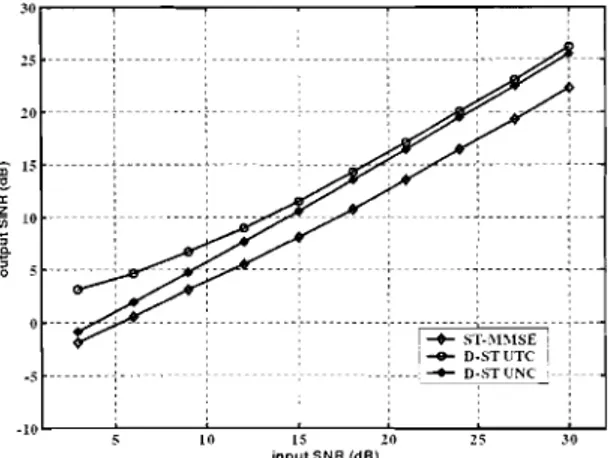
We consider a 2ray multipath Rayleigh fading channel for both the desired and the interferer signals with equal powers. The maximum SINR at the output of the frontend, i.e. at the input of the TE, is obtained by computing the optimum solutions derived in section 3.1, and averaging over 1000 independent channels. In Fig. 4 the output SINR is plotted versus the input SNR (per sensor) when employing an STF with 4 sensors and 2 time taps. The CII is fixed at 0 dB. Fig. S is the same except that we employ only 2 sensors instead of 4. When 4 sensors are used, all the spacetime processing solutions exhibit a linear increase in the output SINR as the input SNR increases. Observe that the UNC approximates the STMMSE at low SNRs while at higher SNRs, the UTC and UNC exhibit similar performance. This is an expected result since the maximization of the SINR under the UNC is based on the interference subspace. When the SNR is low, the noise power contribution to the subspace spanned by q min in (22) is higher than the interferer signal power, causing a distortion on the optimization of the receiver parameters. Reducing the number of sensors to 2, the output SINR for both DST strategies still have a linear increase with the input SINR, while the STMMSE exhibits a floor aroundS dB. This result shows the ability of the DST strategy to work well with a reduced number of sensors.
5
Revista da Sociedade Brasileira de Telecomunicacoes Volume 18, Numero 1, Junho de 2003
SPLMMMMMLMMMセMMセM⦅⦅⦅⦅LMMセMM⦅⦅⦅L⦅⦅⦅⦅L
I eD·ST UTe I
---' ... D·STUNC
⦅iolMMセMMZGZ⦅M⦅⦅⦅⦅ZGZMM⦅⦅⦅WZZ⦅⦅M⦅⦅ZG」ZMM⦅⦅A⦅ZZBMMMj
15 10 25 30
input SNR (dB)
セMM
! -+-stᄋセimse !
ャッヲMMMMMMMMLMMMMMMMMMMMZMMMMMセZZZN⦅GB
QUセMMMMMMMM[ : :
-.0"'-20fif セMMMMMMMMMMMZGMMM ,,f/Y
25 f - -- - - --セ - - - -
---Figure 4. Output SINR versus input SNR for the DST UTC, DST UNC and STMMSE. 2ray multipath Rayleigh fading channel for the desired and the interferer users. C/I= 0 dB. STF with 4 sensors and 2 time taps.
30,,,,____,,___,____,
LLセMMMMMセ : : , MセMMMMMMMM セ 1
20f i--- f c: : MMセ
"
セ 15
セ 10 f , , " ---""t:K"----, . セ
5
10 GMM⦅セ _ _セ _ __':__ ___,''___ ___'__ ___:':____J
15 20 25
input SNR (dB)
Figure 5. Output SINR versus input SNR for the DST UTC, DST UNC and STMMSE. 2ray multipath Rayleigh fading channel for the desired and the interferer users. C/I= 0 dB. STF with :2 sensors and 2 time taps.
in the performances of the UTC and UNC around 4 dB. The former results show that the DST receiver employs all the degrees of freedom available at the frontend filter to cancel CCI only, thus maximizing the SINR for the TE. Furthermore, when there are more resolvable multipaths than sensors, the STMMSE offers a poor output SINR. As a consequence, residual CCI will be present at the input of the TE, degrading the overall receiver performance. Simulation results showed that the performance of the second optimization criterion (section 3.2) is similar to that of the UNC criterion in most of the considered scenarios.
5.2 BEAMFORIVIING ARRAY PATTERN
The beamforming array pattern is estimated by training an AA frontend under the STMMSE, DST UTC and UNC criteria over 500 iterations. The classical RLS algorithm [18] is used for adaptation. We consider two propagation scenarios. The multipath parameters are indicated in tables
:: .__ :_u_; : __ ; : :
セMMMセMM
" I.
セ
•
I •
+ !オセ
2 11 ;:;;;
''';;;-"
セ 10セ
8
MMMMMゥMMMMMMセMMMMMlMMMM
o ' "
- - - -Mセ - - - - + - - - - <
-,
,
,
I-+-
STI\1I\lSE, I : eD.ST UTe
4 MMMMMセMMMMM[MMMMMtMMMMMM
1:
1セ dNstャセc" ,
----,---..,---,---,---" ,
10 8 6 --I 2 0 10
C/l(dB)
Figure 6. Output SINR versus CII for the DST UTC, DST UNC and STMMSE. 2ray multipath Rayleigh fading channel for the desired and the interferer users. The input SNR is 20 dB. STF with 4 sensors and 2 time taps.
:i
=::
セ][セセQQZコMゥMAMオMM
I ... D-STUNC :
16
セ 12 MMMセMM ,
c:
, ,
セ -:
;---;---, , , , ,
I • I , , , I
-- ---....----+----'-- ;,---,---,---:---:---MセMMMMMセMMMMMセMMMM
10 8 6 --I 2 0 10
C/I(dB)
Figure 7. Output SINR versus CII for the DST UTC, DST UNC and STMMSE. 2ray multipath Rayleigh fading channel for the desired and the interferer users. The input SNR is 20 dB. STF with 2 sensors and 2 time taps.
Table 1. Multipath parameters for scenario 1 Scenario I DOA I Delay (T) IGain User Paths 30°,0°, 30° 0,1,2 1,1,0.5
Interferer Paths 60°,60° 0, 1 1, 1
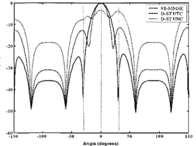
1 and 2. We employ an AA of 5 and 4 sensors for scenarios 1 and 2, respectively. Figs. 8 and 9 show the beamforrning array patterns after the convergence of the receiver parameters. We assume the lsymboldelayed path of the desired user at 0° as a reference (desired signal for STMMSE). Note that in scenario 1 the zerodelayed and :2symboldelayed paths of the desired user are situated outside the mainbeam of the array while in scenario 2, the Isymboldelayed path at 6 ° is situated in the mainbeam of the array,
A. L. F. de Almeida, F. R. P. Cavalcanti , J. C. M. Mota, and C. E. R. Fernandes
Decoupled Space-Time Processing for CCIIISI Cancellation in Mobile Communications Systems
'.
セ
c
o
1 ST]\IlHSE
I ----D-51' UTe
, D·STUNC
...
·10 ..セ...\ ·20
50 ·.0
100 50 0 50 100 150
Angle (degrees)
Figure 8. Beamfonning array pattern for the DST UTC, DST UNC and STMMSE criteria after convergence. Scenario 1. AA of 5 sensors.
·5 ·10
.. __ ...;J'.. ..,.. ... - - ..., \
13 20
'.
セ
'"
0 25o
·30 ·35
I
·.0 STMMSE
' ----DSTUTC
I ... DSTUNC I ·-/.5
50
100 80 ·60 40 ·20 20 40 60 80 100
Angle (degrees)
Figure 9. Beamfonning array pattern for the DST UTC, DST UNC and STMMSE criteria after convergence. Scenario 2. AA of 4 sensors.
two interferer paths. The vertical lines show the directions of the user paths. Since there are more sensors than resolvable multipaths, the STMMSE solution succeeds in nulling out all the multipaths. This means that the STMMSE performs spatial equalization while the two DST approaches perform CCI cancellation only. This is in agreement with the optimization criteria. Fig. 8 also shows that the DST UTC better preserves the desired path at 0 0, at the expense of some attenuation in the direction of the two other paths at 30
°
and 30°. On the other hand, the DST UNC attempts to equally preserve all the desired paths, at the expense of some loss in the direction of the desired path at 0°. However, the output SINR of both approaches is similar. Note that the DST receiver needs an equalizer to suppress the two user paths, since they are not discriminated by the frontend.In Fig. 9 it can be seen that the STMMSE, in an attempt to null out the user path at 60, causes a attenuation in the direction of the desired signal at 0 0. Note that both DST approaches attempts to preserve all the desired user paths. As a consequence enhanced CCI cancellation is obtained. The DST UTC presents the best performance in this case.
114
ST:\,[MSE
... " D·STllTC
セNセ 0.51' lTNC
w
'"
"
50 100 150 200 250 300 350 -/.00 -/.50 500
iterations
Figure 10. Mean square error convergence for the DST UTC, DST UNC and STMMSE. Scenario 1. AA of 5 sensors.
セiM ST·MMSE
, ... DSTliTC I · m__ '> DS1' llN C
w '"
"
50 100 150 200 250 300 350 400 1.50 500
iterations
Figure 11. Mean square error convergence for the DST UTC, DST UNC and STMMSE. Scenario 2. AA of 4 sensors.
Table 2. Multipath parameters for scenario 2
Scenario I DOA I Delay (T) I Gain User Paths 0°, 6°,30° 0,1,2 1,1,0.5
Interferer Paths 50° 0 1
Note that in the DST UNC, the array pattern presents an undesirable attenuation towards the desired path at 0 0.
5.3
MEAN SQUARE ERROR CONVERGENCEThe mean square elTor behavior is showed in Figs. 10 and 11 for scenarios 1 and 2, respectively. Note that in scenario
Revista da Sociedade Brasileira de Telecornunicacoes
Volume 18, Numero 1, Junho de 2003
6.
LINK-LEVEL SIMULATION RESULTS
The SINR defined in section 3 for the DST design is a good metric to evaluate the performance of the first stage of the receiver. By maximizing the SINR at the input of the equalizer, the power of the lSI channel is maximized over CCI plus noise. However, for DST receivers the SINR is not a reliable metric to indicate how difficult the equalization process could be. In other words, the overall receiver performance depends on how the equalizer is designed to handle the ECIR and to provide the best estimate of the transmitted sequence. The equalizer performance in the DST strategy is the focus of this section. We employ the DST strategy with an MLSE equalizer (DSTMLSE) or a DDFSE equalizer (DSTDDFSE) and their performances are compared with those of their conventional counterparts, i.e. the STMLSE and the STDDFSE. Besides, we employ
0:
W
Ell
10 12 16 18 20
EblNo (dB) [0' L...
:::::
セZsセセセse !::---'-...
-.---
t"--.___
<,
'0
-<,
...
...
...,
IU •
Figure 12. Performance of the DSTMLSE versus the STMLSE on the TU scenario as a function of the input SNR. Single cochannel interferer, CII= 3 dB. STF with N
=
3 and M=
2 taps., ,
N⦅MMMセMMMMMMMMMMMMMMMMMMM
,, MMMMセMMMMMM
---__________L
, j., ,
, ,
'"
$
1O-J!
, ,
, ,
. ._---,---
---_.--f:::::::::::::::::::::::::::::::::···::·
セMMM - MMMMMMMMMMMMMMMMMセ
---'---MMMMMMMMセ
---...,----10 -5 U 10
ClIldB)
the first optimization criterion under the UTC approach to adapt the D-ST receivers, since it has provided good results under different equalizer options and scenarios [22-24]. For evaluation of the bit-error-rate (BER) performance of the D-ST receiver structures we use the channel model suggested by COST 259 recommendations [25]. The COST 259 is a wideband directional channel model that provides channel impulse responses in both spatial and temporal domains. We consider the macrocell radio environment of a COST 259 simulator to generate the channel impulse responses. We consider the Typical Urban (TU) and a Bad Urban (BU) scenario. For the generation of the impulse responses, the desired user and a single co-channel interferer were uniformly distributed within a 120 0
sector and cell radius was assumed to be 500 m.
The channel is static over a time interval of a time-slot. Except for the pulse shaping function, where we employed
: :
-e":
•
:
-
---::::: ST.DDFSE
10 12 14 16 18 20
EblNo (dB)
IU
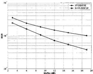
Figure 14. Performance of the D-ST-DDFSE versus the ST-DDFSE on the BU scenario as a function of the input SNR. Single co-channel interferer, CII= -3 dB. STF with
N
=
3 and M=
2 taps.1
10. MMMMMセMMMMMMMMMMM - __J __
: _ ::::::::::::::::::::::::::::::::::: -+-ST-DDFSE ,
iLZZMェMK]セBBZェ
J"
セ QoMセ⦅
t
r
....
_ セ
,
r::::::;.:::::::....::::::,:::::::::
MMMMMMMMMMセMMMMMMMMMMMMMMMMMMMZMMMMMMMMMMMMMMMMMMMZMMM M M M M
10"'--'MセMMMMMMMGMMMMMMMGMMMM
-10 ·5 10
CII(dB)
Figure 13. Performance of the D-ST-MLSE versus the Figure 15. Performance of the D-ST-DDFSE versus the ST-MLSE on the TU scenario as a function ofthe CII. Single ST-DDFSE on the BU scenario as a function of the CII. co-channel interferer. Eb/No is fixed at 20dB. STF with Single co-channel interferer. Eb/NO is fixed at 20dB. STF
N
=
3 and M=
2 taps. with N=
3 and M=
2 taps.A. L. F. de Almeida, F. R. P. Cavalcanti , J. C. M. Mota, and C. E. R. Fernandes
Decoupled Space-Time Processing for CCIIISI Cancellation in Mobile Communications Systems
a raised cosine with 35% roll-off, our system context is the Enhanced Data Rates for Global Evolution (EDGE). Thus, we use 8-PSK modulation and each run represents a transmitted time-slot of 140 symbols from which 26 are for training [26, 27]. The RLS algorithm is used for training. Previous simulation results have shown that the TU scenario is characterized by the presence of a unique cluster of scatterers located local to the base station, leading to small delay spread. In BU scenario, additional and strong clusters of scatterers lead to larger delay spread [23]. Thus, the D-ST MLSE receiver was employed on the TU scenario, since most of the delay spread is concentrated within 1 symbol period. The D-ST DDFSE was employed on the BU scenario, where delay spread spans more symbol periods.
The front-end is an STF with N = 3 and 1\1 = 2 taps. The training filter has 1 precursor tap and 5 post-cursor taps. In order to minimize the precursor energy of the estimated ECIR, we employ a feedfoward filter (see Fig.3) prior to the the MLSEIDDFSE equalizer. In both the D-ST-MLSE and the ST-MLSE, the Viterbi trellis has memory of 1 symbol. For the DDFSE equalizer, the feedback trellis has a memory of 6 symbols.
In Figs. 12 and 14 the BER is plotted versus the input
Eb/P'lo per sensor. The CII is set to -3dB. Fig. 12 shows that
a considerable performance improvement of D-ST-MLSE over ST-MLSE is verified on the TU scenario. The Eb/No
gain of D-ST-MLSE is more than 5 dB at 1% target BER. The D-ST-DDFSE and ST-DDFSE are shown in Fig. 14. The performance improvement of D-ST-DDFSE over its conventional counterpart on the BU scenario is evident. Note that the gain of D-ST-DDFSE increases as the input
Eb / No increases. For a target BER of 1% the EblN0 gain
of D-ST-DDFSE over ST-DDFSE is remarkably 10dB. The performance gains of the D-ST-MLSE and D-ST-DDFSE are due to an enhanced CCI cancellation, since the STF utilizes all its degrees of freedom for this purpose. The D-ST receivers also perform superior lSI equalization, since the residual CCI at the input of the MLSEIDDFSE is minimized and the path diversity of the desired user channel is better explored. These facts explain the performance gains of the D-ST receivers.
In Figs. 13 and 15, we fix the input Eb/NO at 20dB and plot the BER as a function of the CII. It should be noted that such gains in terms of BER can be interpreted as user capacity gains in terms of CII. For example, if the target BER is fixed at 4· 10-3 the D-ST-MLSE provides a CII gain ofs dB on the TU scenario over the ST-MLSE. At the same target BER, the CII gain of D-ST-DDFSE over ST-DDFSE is nearly 15 dB. In [24] we have shown that such link-level gains offered by the D-ST strategy can be translated into throughput gains at the system-level.
7.
CONCLUSIONS
In this work we have presented the D-ST strategy for separating CCI cancellation and lSI equalization. We have seen that the idea of D-ST processing is to separate CCI and lSI treatment in two stages. This is achieved by joint optimizing the parameters of the front -end filter and the
equalizer with the use of a training filter. As a consequence, the front-end suppresses only the CCI leaving the lSI to be suppressed by a time-domain equalizer, thus minimizing the problems of insufficient spatial degrees of freedom and residual CCI. The BER performance of an adaptive D-ST receiver employing MLSE and DDFSE equalizers was evaluated under the TU and BU scenarios of the COST 259 channel model. It was verified that the proposed D-ST receivers have superior performance as compared to its conventional counterparts in scenarios limited by lSI and CCI. As shown in [24] such link-level gains offered by the D-ST can be translated into throughput gains at the system-level as well as higher user capacity.
ACKNOWLEDGEMENTS
The authors are thankful to C. M. Panazio for his valuable help and for useful discussions. The authors would like to express their thanks to CAPES and Ericsson Research-Brazilian Branch for the financial support,
REFERENCES
[1] J. H. Winters. "Optimum combining in digital mobile radio with co-channel interference," IEEE J. Select. Areas COml11U1l.,
vol. SAC-2, pp. 528-539. July 1984.
[2] S. Anderson. "An adaptive array antenna for mobile communication systems," IEEE Trans. Veh. Technol., vol. 40, pp. 230-236. Feb. 1991.
[3] J.-. W. Liang, "Interference reduction and equalization with space-time processing in TDMA cellular networks," Ph.D. dissertation. Stanford University. 1998.
[4] C. A. Papadias and A. J. Paulraj, "Space-time processing for wireless communications," IEEE Signal Proc. Mag, vol. 14. no. 5, pp. 49-83, Nov. 1997.
[5] E. Lindskog. "Multichannel maximum likelihood sequence estimation," Proc. of the 47th IEEE Veh. Technol, Conf.. May
1997.
[6] G. E. Bottomley and K. Jamal, "Adaptive arrays and MLSE equalization." Proc. of the 45th IEEE Veh. Technol. Conf., pp. 50-54, luI. 1995.
[7] T. Boros, G. G. Raleigh, and M. A. Pollack, "Adaptive space-time equalization for rapidly fading communication channels." Proc. Globecom, pp. 984-989, 1996.
[8] F. Pipon. P. Chevalier, P. Vila. and J. J. Monot, "Joint spatial and temporal equalization for channels with lSI and CCI - theoretical and experimental results for a base station reception," First IEEE SPAWC. 1997.
[9] J.-. W. Liang, J.-. T. Chen, and A. J. Paulraj, "Two-stage hybrid approach for CCIIISI reduction with space-time processing,"
IEEE Communications Letters, pp. 163-165, Nov. 1997. [10] J.-. W. Liang, J.-. T. Chen, and A. J. Paulraj, "A space-time
filtered viterbi receiver for CCIIISI reduction in TDMA systems," Circuits. Systems. and Signa! Processing, pp. 85-102,1998.
[11] S. Fanfoni et. all, "Space-time processing for co-channel interference rejection and channel estimation in GSMIDCS systems," IlRSl Intern. Symp, Sig.. Syst., and Elect.. ISSSE 98.
pp. 152-155, 1998.
[12] M. L. Leou, C.
c.,
Yeh, and H. J.u,
"A novel hybrid of adaptive array and equalizer for mobile communications,"Revista da Sociedade Brasileira de Telecomunicacoes Volume 18, Numero 1, Junho de 2003
IEEE Trans. Veh. Technol., vol. 49. no.T, pp. 1-10, Jan. :WOO.
[13] M. A. Lagunas, J. VidaL and A. 1. Perez-.Neira, "Joint array combining and MLSE for single-user receivers in multipath gaussian multiuser channels," IEEE 1. Select. Areas Commun.,
vol. 18, no. 11, pp. 2252-2259, Nov. 2000.
[14] R. Friedman and Y. Bar-Ness, "Combined channel-modified adaptive array MMSE canceller and viterbi equalizer," Proc. ofIEEE Velz. Techno/. Coni, vol. 1, pp. 219-213, 2001. [15] M. Fujii, "Joint processing of an adaptive array and an MLSE
for multipath channels," Proc. of IEEE Int. Conunun COI{t:,
vol. 2, pp. 636-640, 1997.
[16] C. H. A. Duel-Hallen, "Delayed decision-feedback sequence estimation," IEEE Trans. Commun.. vol. 37. no. 5, May 1989. [17] K. J. Molnar and G. E. Bottomley. "Adaptive array processing MLSE receivers for TDMA digital cellular/PCS communications," IEEE J. Select. Areas Commun., vol. 16, no. 8. pp. 1340-1351, Oct. 1998.
[18] S. Haykin, Adaptive Filter Theory, 4th ed .. ser. Perntice Hall Information and System Science, T. Kailath, Ed. New Jersey: Prentice Hall, 2000, iSBN: 0-13-090126-1.
[19] N. Al-Dhahir, "FIR channel-shortening equalizers for MIMO lSI channels," IEEE Trans. Commun., vol. 49, no. 2, pp. 213-218, Feb. 2001.
[20] R. A. Horn and C. R. Johnson, Matrix analysis. Cambridge University Press. 1990.
[21] J. G. Proakis, Digital Communications, 3rd ed., ser. Electrical Engineering. McGraw-Hill International Editions, 1996. [22] C. M. Panazio and F. R. P. Cavalcanti, "Decoupled space-time
processing: performance evaluation for a TDMA system,"
Proc. ofIEEE Velz. Technol. COI(t:, 200 I.
[23] A. L. F. de Almeida, C. M. Panazio, F. R. P. Cavalcanti, and C. E. R. Fernandes, "Space-time processing with a decoupled delayed decision-feedback sequence estimator," Proc. of 55th IEEE Veh. Techno/. COI(t:, vol. 3, pp. 1269-1273,2002. [24] A. L. F. de Almeida, F. R. P. Cavalcanti, C. E. R. Fernandes,
and J. C. M. Mota, "System-level evaluation of space-time processing for EDGE," Proc. of56th IEEE Veh. Technol. Coni,
vol. 2, pp. 763 -767, 2002.
[25] L. M. Correia, Wireless Flexible Personalized
Communications, COST 259: European Co-operation in
Mobile Radio Resource. Wiley, 2001.
[26] 3GPP, "Digital cellular telecommunications system (Phase 2+): modulation," 3GPP, TS 43.064 v.8.1.0, Tech. Rep., jul 2001. [Online]. Available: http://www.3gpp.org
[27] 3GPP. "Digital cellular telecommunications system (Phase 2+): radio transmission and reception," 3GPP, TS 45.005 v.. Tech. Rep., jul 2001. [Online]. Available: http://www.3gpp.org
Andre L. F. de Almeida was born in Teresina, Piaui, Brazil in 1978. He received his Bachelor Degree in Electrical Engineering from Universidade Federal do Ceara (UFC), Brazil, 2002. Presently, he is a Master Student in the same University. Since 2000 he has been with the Wireless Telecom Research Group (GTEL) located at the Teleinformatics Engineering Department (DETI), UFC. He is also member of the IEEE Communications Society and the Sociedade Brasileira de Telecomunicacoes. His research interests are space-time processing and equalization, smart antennas, space-time coding and MIMO systems. Presently, he is working on the final stage of his thesis.
Fco, Rodrigo P. Cavalcanti received his doctor's degree from the Communications Department of the Faculty of Electrical Engineering at the University of Campinas - Unicamp, in 1999. From 1999 to 2001 he was a post-doctorate researcher at the
Electrical Engineering Department of the Federal University of Ceara (UFC). Since 2002 he is an Associate Professor of the Teleinformatics Engineering Department in the same University. Currently Dr. Cavalcanti coordinates the GTEL. the Wireless Telecommunications Research Group at UFC. His research interest are related to the physical layer and access networks of wireless and mobile communication systems as a general.
Joao Cesar M. Mota was born in Rio de Janeiro, Brazil, on
november 17, 1954. He received B.Sc degree in Physics from the Universidade Federal do Ceara (UFC), Brazil, in 1978, the M.Sc. degree from Pontiffcia Universidade Cat6lica (PUC-RJ), Brazil. in 1984, and Ph.D. degree from Universidade Estadual de Campinas -UNICAMP, Brazil, in 1992, all in telecommunications engineering. Since August 1979, he has been in the UFC, and actually he is Full Professor with Teleinformatics Engineering Department. Dr. Mota worked in Institut National des Telecommunications, France, as invited Professor on 19961998. He was general chairman of the 19t h Brazilian Telecommunications Symposium SBrT'200I.
His research interests include digital communications, adaptive filter theory and practice and signal processing. He is member and counsellor of the Sociedade Brasileira de Telecornunicacoes, and member of the IEEE Communications Society and IEEE Signal Processing Society. He is counsellor of the IEEE Student Branch ofUFC.