Transceiver Architectures in Multiuser MIMO
Environments with Different Power Allocations
Igor M. Guerreiro, Icaro L. J. da Silva, Walter C. Freitas Jr., Charles C. Cavalcante
Abstract— In this paper we present efficient MIMO transceiver architectures evaluated in a multiuser environment. In this context we consider traditional MIMO transmit structures and also hybrid ones proposed in [6] capable of achieve diversity and multiplexing gains. Our results shown that in a multiuser environment the MIMO transmit structures of the desired user has a crucial impact in the performance due the diversity orders of the multiple layers in the MIMO structure.
Keywords— 4G, MIMO, diversity, multiplexy, multiple anten-nas, interference, multiuser.
I. INTRODUCTION
The main requirements that apply to fourth-generation (4G) mobile systems are support for high data rates and high quality of service (QoS). However, the mobile units must be smaller and with low complexity, being able to operate in different radio environments: macro, micro and picocellular; urban, suburban and rural; indoor and outdoor. As the available radio spectrum is limited, higher data rates can be achieved only designing more efficient transmission schemes. Thus, the next generation systems are supposed to have better quality and coverage, being more power and bandwidth efficient. In a multicell context, the increasing number of subscribers requires also a solution for inherent co-channel interference (CCI).
Wireless communication becomes extremely difficult in a multipath environment because the transmitted signal can be severely attenuated, decreasing the link performance. However, communication in wireless channels can be improved using multiple-input multiple-output (MIMO) transceiver architec-tures. The MIMO technology exploits the spatial components of the wireless channel to provide significant capacity gain and/or increase link robustness.
Some diversity techniques are widely used coupled with MIMO systems to reduce the effects of multipath fading environments and improve the transmission reliability without any increase of transmitted power or sacrifice of bandwidth. Space-Time (ST) coding is a transmit diversity technique which extracts diversity without any channel information at the transmitter. In this paper we consider the Space-Time Block Codes (STBC) [2], which generalizes the transmission scheme designed for two transmit antennas [1] and is present in evolved third-generation systems.
MIMO systems can be also used to spatially multiplex data in order to increase spectral efficiency. This gain in
This work was supported by a grant from Ericsson of Brazil - research branch under ERBB/UFC.19 technical cooperation contract. The authors are with the Wireless Telecommunication Research Group (GTEL) from Federal University of Cear´a - UFC. E-mails:{igor,icaro,walter,charles}@gtel.ufc.br.
multiplexing symbols through the MIMO wireless channel is known as Spatial Multiplexing (SM) gain, which increases almost linearly with the numbers of transmit antennas [4]. The multiplexing scheme adopted in this paper was the ver-tical Bell Laboratories Layered Space-Time (V-BLAST) [3], which splits the original data stream into substreams that are transmitted on the individual antennas.
It is known there is an important trade-off between diversity and multiplexing gains which explores the capacity of both structures [5]. Recently, new MIMO transceiver architectures named Hybrid MIMO Transceiver Schemes (HMTS) [6] using jointly ST and SM structures have been proposed to obtain advantages of both diversity and multiplexing gains. The rationale of the HMTS considers a layered architecture as V-BLAST, but some layers are coded with SBTC.
Several works have already studied the capacity of MIMO transceivers discussed previously. However, most of works do not consider CCI and in a typical cellular radio application, the performance-limiting impairment is the frequency reuse from the other cells (co-channel) that transmit in the same frequency of the desired user. In this context, not considering this multicell system feature is a non-real assumption. The value of CCI mitigation in wireless networks is that it enables better frequency reuse and hence improves networks spectrum efficiency.
In this context, a CCI canceling method using a MIMO spatial filter based on Minimum Means Square Error (MMSE) is introduced to suppress CCI placed before the decoder. This method was proposed in [7] for the Alamouti´s STBC scheme. In this paper, we analyze the performance of this CCI canceling method for different MIMO transceiver schemes, namely STBC, V-BLAST and HMTS, over different power levels of the interferer user.
The organization of this paper is as follow. In Section II we show the system model proposed for a multiuser MIMO envi-ronment. The transmitter and receiver schemes are presented in Section III and IV jointly with mathematical demonstration, respectively. Simulation results are given in Section V and, finally, our conclusions are drawn in Section VI.
II. SYSTEMMODEL
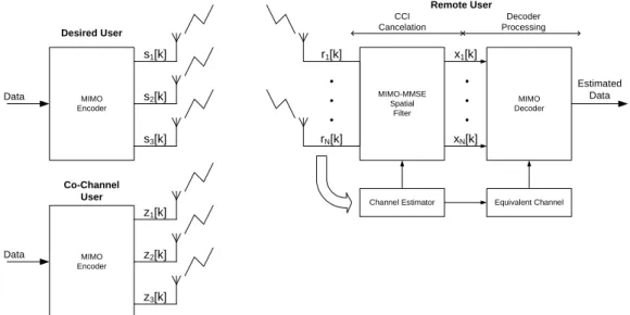
We consider a multiuser (MU) environment with three transmit antennas and N receive antennas at the remote unit of the desired user. We consider the signal which introduces co-channel interference (CCI) is also sent by three antennas. A system figure is presented in Fig. 4.
Labo-MIMO Encoder
MIMO Encoder
Desired User
Data MIMO-MMSE
Spatial Filter
Data
MIMO Decoder
Channel Estimator Equivalent Channel
Co-Channel User
Estimated Data
s1[k]
s2[k]
s3[k]
z1[k]
z2[k]
z3[k]
r1[k]
rN[k]
x1[k]
xN[k] CCI
Cancelation
Decoder Processing
Remote User
Fig. 1. System model general structure.
ratories Layered Space Time (V-BLAST) or a Hybrid MIMO Transceiver scheme (HMTS) to encode the symbols.
Each coded symbol is transmitted over a quasi-static rich-scattered flat fading channel from a different antenna. The fading between each transmit and receive antenna pair is assumed to be independent, modeled by circularly symmetric Gaussian random variables. The total transmitted power is fixed and the transmitted burst has length L, defined as the time over the channel is quasi-static.
At the interferer transmit branch we assume a single MIMO transceiver scheme and the same channel model. The interferer signal arrives at the receptor with a power levelPiconsidered
in the system model. Thus, at any time-instantk the received signal can be expressed as
r[k] =Hs[k] +pPiGz[k] +n[k], (1)
where HN×3 = [H(1) H(2) H(3) ] denotes the MIMO
channel matrix and the column vectors[k]denotes each row of
the coded matrix of complex transmitted symbols S3
×T. This
coded matrix is constant over a signalizing period, defined as the number of time slots to transmit the coded block and represented by T. The matrix G and the vector z[k] are
similarly defined for co-channel interferer signal. The matrix
nN×1 is a zero-mean, unit variance and complex-Gaussian
distributed noise that is spatially and temporally white. Our general model considers an spatial filter based on Min-imum Mean Square Error (MMSE) for interference canceling (IC) at the receiver structure before the decoder. After this previous filtering, the signal represents an estimation of the desired signal, ready to be decoded as follows:
• Using STBC decoder [2], if the transmitter uses a STBC
scheme;
• Using linear or non-Linear detection scheme, if the
trans-mitter uses a V-BLAST scheme;
• Using schemes coupled, if the transmitter uses a hybrid
scheme.
It is important to remember that our model considers that the receiver knows both desired and interferer channels information.
III. MIMO SCHEMES FORM = 3TRANSMITANTENNAS We have chosen three possible configurations for the sce-nario previously described. We assume that the interfering transmitter uses a MIMO hybrid scheme G2+1 [6], without any loss of generality. We detail these three possibilities for the transmitter.
A. Space-Time Block Coding
Space-time codes use channel coding techniques combined with multiple transmit antennas, introducing temporal and spatial correlations into signals transmitted from different antennas. We now present the first proposed STBC scheme, called G3 [2]. This scheme employs a three-element transmit antenna array which are space-time coded. The transmitted signals can be organized in the equivalent space-time coding matrix given by
SG3[k, . . . , k+ 7] =
s1 s2 s3
−s2 s1 −s4
−s3 s4 s1
−s4 −s3 s2
s∗
1 s∗2 s∗3
−s∗
2 s∗1 −s∗4
−s∗
3 s∗4 s∗1
−s∗
4 −s∗3 s∗2
, (2)
where the spatial dimension varies column-wise and the temporal dimension row-wise. Since T time slots are used to transmit P information symbols, we define the effective spectral efficiency equal toη= P
T ·log2Mbps/Hz, whereM
is the modulation cardinality.
the number of time slots required to transmit the space-time coded symbols through the multiples antennas is 8, giving a code rate of1/2 andη=12·log2M bps/Hz.
We consider also in this work another STBC scheme called H3 [2], which has an equivalent space-time coding matrix given by
SH3[k, ..., k+ 3] =
s1 s2 √s3
2
−s∗
2 s∗1
s3
√
2 s∗
3 √
2 s∗
3 √
2
−s1−s∗
1+s2−s∗ 2 2 s∗
3 √
2 −
s∗ 3 √
2
s2+s∗ 2+s1−s∗
1 2
. (3)
Similarly, using H3 scheme we obtain a code rate of3/4and η = 3
4 ·log2M bps/Hz. Both H3 and G3 schemes provide
diversity gain.
B. Space Multiplexing Scheme
Another approach for multiple-antenna transmission is to focus on the maximization of the transmission rate. To obtain this goal, we consider the V-BLAST scheme, where all the antennas are used to multiplex different symbols in each time slot. In this scheme each different multiplexed symbol at a signaling period is defined as a layer. In the case of three transmit antennas we have three layers. The transmitted signals at time instant k, considering three transmit antennas, can be organized in the equivalent space-time coding matrix
SV
−BLAST[k] =
£
s1 s2 s3
¤
. (4)
As spatially-multiplexed symbols cause interference in each other, signal processing is mandatory at the receiver in order to cancel interference from each layer and from co-channel interferer. Using V-BLAST pure we obtain a multiplexing gain proportional to the number of transmit antennas, in this case equals to 3, resulting in η= 3·log2Mbps/Hz.
C. Hybrid MIMO Scheme
As seen in the last two subsections, MIMO antenna sys-tems may provide diversity gain, using a STBC scheme, or multiplexing gain using V-BLAST scheme. There is, however, a trade-off: the diversity gain can only be increased if the multiplexing gain is sacrificed [5]. Hybrid MIMO transceiver schemes (HMTS) combine pure diversity schemes with pure spatial multiplexing schemes. In hybrid systems, some layers are space-time coded and, for the remaining layers, a V-BLAST approach is used. With this idea, hybrid MIMO schemes achieve a compromise between spatial multiplexing and transmit diversity gains [6].
We have chosen in this work the hybrid scheme G2+1, which employs a three-element transmit antenna array with two spatial multiplexing layers. A standard G2 space-time block code is used at the first layer and the other layer is not space-time-coded, following the V-BLAST approach. In the G2+1 scheme, the transmitted signals can be organized in the equivalent space-time coding matrix
SG2+1[k, k+ 1] =
·
s1 s2 s3
−s∗
2 s∗1 s4
¸
, (5)
where the spatial dimension varies column-wise and the tem-poral dimension row-wise.
From Eq. (5), it can be seen that4information symbols (two from each multiplexing layer) are transmitted in2 time slots, given an effective spectral efficiency equal to η= 2·log2M
bps/Hz.
IV. MIMO RECEIVINGSTRUCTURES WITHCCI MITIGATION
Considering our system model, the incoming signal arriving at the receiver is the superposition of an interfering signal from co-channel with different power levels and the desired signal. A receiving architecture based on a MMSE spatial filter to interference cancelation coupled with a decoder scheme to estimate each transmitted symbol was previously proposed [7] when the transmitter uses Alamouti’s scheme. In this section we describe this MMSE IC algorithm coupled with decoder for each transmission MIMO scheme considered in this work.
A. CCI Mitigation with MMSE Spatial Filter
The idea behind a simple MMSE IC algorithm is mini-mizing the mean square error between the desired signal and MMSE filter output. At each instantkthe MMSE filter output is expressed as
x[k] =WICHr[k], (6)
whereWIC= [w1. . . wN ]withwn= [w1 . . . wN ]T is a
N×N matrix for the spatial filter coefficients. In a multiuser context the desired signal will be the ST coded or SM symbols and the error signal can be represented by
e[k] =WICHr[k]−rd[k] =WIC H
r[k]−(Hs[k] +n[k]) (7)
whererd[k]represents the signal that would be received from
the desired user if we had not considered the co-channel interferer. Thus, the MMSE cost function is expressed as follows
JMMSE=E{kWIC H
r[k]−rd[k]k2}. (8)
Minimizing the above cost function we found the optimal solution
WIC=R−1
rrRrrd, (9)
where Rrr = E{r[k]r
H
[k]} and Rrrd = E{r[k]r
H d[k]} are
the input covariance matrix and a cross-correlation matrix, respectively. We can write this optimal solution in another way considering that we have both channel knowledge as follow
WIC= (HHH+PiGG H
+σ2nIN)−1(HH H
+σn2IN).
(10) After CCI minimization, the resulting MMSE filter output can be written as
x[k] =H′s[k] +n′[k] (11)
where H′ =WHHb
is an equivalent MIMO channel matrix consisting of the original space-time coded channel modified by the coefficients of the MMSE filter. The term n′[k] is
noise and residual interference, whose covariance is given by Rn′n′ = σ2nWIC
H
WIC. We could chose another CCI
canceling filter but MMSE has a better performance than other linear filters, e.g. Zero Forcing (ZF) algorithm which do not suffer from noise enhancement.
B. MIMO Decoding Schemes after CCI mitigation
After CCI cancelation we are now able to estimate each transmitted symbol at the receiver for an specific MIMO transmission scheme. The MMSE filter output can be seen as a simple MIMO model considering the equivalent MIMO channel matrix H′ and defined in the end of the last
sub-section. In this subsection we describe the decoders for the MIMO schemes considered previously.
1) G3 and H3 Decoder: Taking the MMSE filter output we use a simple linear detection scheme based on each coding matrix, as shown in Fig. 2.
MU MIMO-MMSE Spatial
Filter
Channel Estimator Equivalent Channel
r1[k]
rN[k]
Remote Receiver
x1[k]
xN[k]
STBC
ML - Decoder EstimatedData
s[k]
Fig. 2. Spatial Filter MMSE + STBC Decoder.
The incoming signals are combined in each transmission block period to decode the symbols information. Once the noise in x[k] is no more white, changed by the WIC filter,
there is correlation between the samples. Based on the condi-tional probability density ofx[k][7], the maximum likelihood
(ML) decoding of the space-time coded signal s[k]should be
based on the minimization of the following branch metric
(x[k]−H′s[k])HR−1
n′n′(x[k]−H
′
s[k]) (12)
over all possible codewords of the space-time code used in the transmission.
This metric increases the decoding performance but raises its complexity. In our work we have assumed the Euclidian Distance as our decision metric, which simplifies our decoding process.
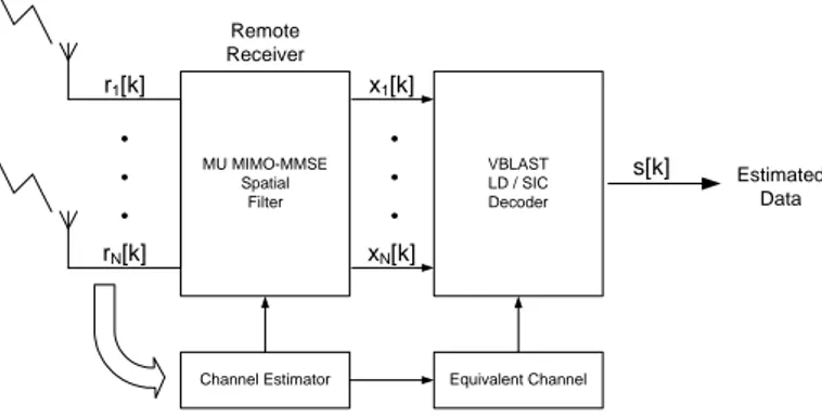
2) V-BLAST Decoder: The symbols multiplexed spatially interfere in each other, then some signal processing at the receiver has to be made in order to cancel interference. Linear methods were proposed and we have chosen to evaluate in this work a method based on MMSE estimation, as described previously to canceling the CCI.
In this case, the desired signal is s[k], giving the cost
function written bellow
JMMSE=E{kWVBLASTx[k]−s[k]k2}. (13)
MU MIMO-MMSE Spatial
Filter
VBLAST LD / SIC Decoder
Channel Estimator Equivalent Channel
Estimated Data
r1[k]
rN[k]
Remote Receiver
x1[k]
xN[k]
s[k]
Fig. 3. Spatial Filter MMSE + V-BLAST Decoder.
After the minimization of the cost function, we have the spatial filter coefficients given by
WVBLAST =RsxRxx−1, (14)
where Rsx = E{s[k]x
H
[k]} and Rxx = E{x[k]x
H [k]}. Considering the equivalent MIMO channelH′ we have found
another way to calculate the filter coefficients, resulting in
WVBLAST=H′H(H′H′H+R
n′n′)−1. (15)
We can obtain a better performance using non-linear de-tection techniques to canceling the interference. Thus, we use a successful IC algorithm called successive interference cancelation (SIC) where the layers are detected sequentially. The incoming signal from the MMSE filterx[k] goes trough
a linear detector for the first layer, whose output is used to produce a symbol estimation at this layer ˆs1[k]. Then, this
estimation is reduced of the incoming signal for the second layer, generating the signal x2[k]. The process is repeated
successively for each layer, and the signal xi[k], hopefully
free from the interference of the other j < i layers, goes trough a linear filter that tries to canceling the interference from layersj > i. Based on the linear filter output, a symbol estimate ˆsi[k] is produced and the received signal for each
layer xi[k] is also estimated with the interference from the
remainingj > ilayers. This procedure is shown bellow
xi+1[k] =xi[k]−ˆsi[k]hi[k], (16)
wherehi is thei-th column of the equivalent matrix channel hi corresponding to the equivalents channel gains associated
to layer i, andˆsi[k]hi[k] represents the estimated equivalent
interference from thei-th layer. This technique is also known as nulling and canceling algorithm [8].
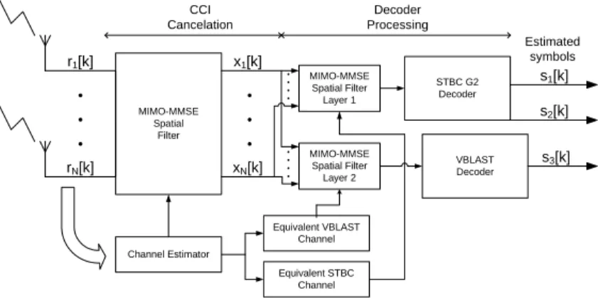
3) HMTS Decoder: We have seen that a hybrid MIMO scheme with three transmit antennas divide the antennas into two layers, one V-BLAST layer to obtain spatial multiplexing gain and an STBC to increase the diversity gain.
Once the CCI have been already filtered, the incoming signalx[k] is a superposition of these two layers. In the case
MIMO-MMSE Spatial
Filter
STBC G2 Decoder
Channel Estimator r1[k]
rN[k]
CCI Cancelation
x1[k]
xN[k]
VBLAST Decoder
Equivalent STBC Channel Equivalent VBLAST
Channel
s1[k]
s2[k]
s3[k] Estimated
symbols
MIMO-MMSE Spatial Filter Layer 1
MIMO-MMSE Spatial Filter Layer 2
Decoder Processing
Fig. 4. Spatial Filtering MMSE + HMTS Decoder G2+1.
In linear detection, another MMSE filter represented byW1
is used for the first layer and the output error vector is
e=W1x−x(1)d , (17)
where x(1)d = [H′(1) H′(2)]S1. Here,S1 is the G2-encoded
signal.
The goal of W1 is to remove the interference from other
layers. This MMSE cost function may be written as
JMMSE=E{kW1x[k]−x(1)d [k]k 2}.
(18)
The optimal coefficients are found by minimizing the above cost function with respect to W1. The solution is given by
W1=R
x(1)
d x
R−1
xx, (19)
which can be represented by
W1= (H′(1)H′(1)H+H′(2)H′(2)H)(H′H′H+Rn′n′)−1.
(20) This second spatial filter makes no attempt to recover the G2-encoded signal: this will be done exploiting the structure of the STC, which leads to a linear receiver that performs ML detection.
The process to detect the V-BLAST layer is similar. Al-though, the input channel matrix to calculate the filter coef-ficients will be the remaining column, thus the W2 can be
expressed as
W2=R
x(2)
d x
Rxx−1, (21)
wherex(2)d [k] =H′(3)S2.
The procedure to find the filter coefficients is just the same as before, minimizing the cost function
JMMSE=E{kW2x[k]−x(2)d [k]k
2} (22)
which results in
W2 = (H′(3)H)(H′H′H+R
n′n′)−1 (23)
This solution using a linear detection scheme is presented in Fig. 4. Another alternative is using a non-linear SIC scheme, where the MIMO MMSE outputx[k]passes just as before by
the G2+1 decoder to estimate the symbols from the first layer. The difference is that theW1filter output will be canceled on
the second layer before calculate the W2 filter coefficients.
In the next section we evaluate the performance of each algorithm and the simulation results.
V. SIMULATIONRESULTS
We present the performance in terms of bit error rate (BER) vs.Eb/N0 in dB by means of numerical results from
Monte-Carlo simulations. Unless otherwise noted, all schemes employ binary-phase shift-keying (BPSK) modulation. We assume a MIMO system with 3 transmit and N receive antennas and one interferer user in different power allocation situations and receiver structures, linear detector (LD) and SIC receiver.
Fig. 5 shows the performance of G3 MIMO STBC transmit scheme consideringN = 4and two different power allocation for the interferer user. As it have been attempted, we can obtain a great performance for adverse link situations such as low SNR levels and high CCI.
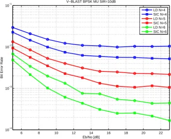
The next graphic presented in Fig. 6 shows V-BLAST MIMO transmit scheme considering the power of the interferer such as SIR=10dB for different number of receiver antennas, N = 4,5 and 6. We can see that using N = 4 receiver antennas is the overloaded case (also called undetermined) since we have more interference that antennas to nulls out each interference (CCI and interference from other layers) for both receivers LD and SIC. Considering SIC a gain is obtained compared with LD, since the last layer will perceive a diversity gain, thus, the already detected layers is nulled from the received signal. Even, with N = 5receive antennas we have a overloaded case. However, with N = 6 we can null out the interferences and SIC provides a diversity gain by the nulled contribution of the detected layers adding diversity to the system. Figure 7 shows the performance considering a SIR=15dB. This is a less restrictive scenario and compared with the case of SIR = 10dB, it presents a lower BER.
0 1 2 3 4 5 6 10−6
10−5 10−4 10−3
G3 BPSK MU N=4
Eb/No [dB]
Bit Error Rate
G3 SIR=0dB G3 SIR=2dB
Fig. 5. Bit Error Rate versus SNR for G3 Scheme for SIR=0db and SIR=2dB.
6 8 10 12 14 16 18 20 22
10−4
10−3 10−2 10−1
V−BLAST BPSK MU SIR=10dB
Eb/No [dB]
Bit Error Rate
LD N=4 SIC N=4 LD N=5 SIC N=5 LD N=6 SIC N=6
Fig. 6. Bit Error Rate versus SNR for V-BLAST Scheme and SIR=10dB.
5 6 7 8 9 10 11 12 13 14 15
10−5 10−4 10−3 10−2
10−1 VBLAST BPSK MU SIR=15dB
Eb/No [dB]
Bit Error Rate
LD N=4 SIC N=4 LD N=5 SIC N=5 LD N=6 SIC N=6
Fig. 7. Bit Error Rate versus SNR for V-BLAST Scheme and SIR=15dB.
0 2 4 6 8 10 12 14 16
10−7
10−6 10−5 10−4 10−3 10−2 10−1
G2+1 BPSK MU SIR=15dB
Eb/No [dB]
Bit Error Rate
LD N=4 SIC N=4 LD N=5 SIC N=5 LD N=6 SIC N=6
Fig. 8. Bit Error Rate versus SNR for G2+1 Scheme and SIR=15dB.
VI. CONCLUSIONS
In this work we evaluated MIMO transceiver architectures in multiuser MIMO environments, thus, CCI is present with varying power levels. In this MU scenario the performance depends of the transmit architecture considered to the desired user, G2+1 architecture outperforms V-BLAST since, G2+1 has lower layers and this increase the diversity order to the last layer to be detected.
We have seen that the MMSE spatial filter can be also employed for CCI cancelation when the transmitter uses V-BLAST or HMTS schemes obtaining good performance, not only for STBC as shown in [7].
REFERENCES
[1] S. Alamouti, “A simple transmit diversity technique for wireless commu-nications,”IEEE Journal of Selected Areas in Communications, vol.16, pp.1451–1458, Oct 1998.
[2] V. Tarokh, H. Jafarkhani, and A. R. Calderbank, “Space-time block codes from orthogonal designs,” IEEE Transactions on Information Theory, vol.5, pp.1456–1467, Jul 1999.
[3] G. J. Foschini and M. J. Gans, “On limits of wireless communications in a fading environment when using multiple antennas,”Wireless Personal Communications, v.6, n.3, pp.311–335, Mar 1998.
[4] E. Telatar, “Capacity of multi-antenna gaussian channels,” Bell Labs Tech. J., June 1995.
[5] L. Zheng and D. Tse, “Diversity and multiplexing: a fundamental trade-off in multiple antenna channels,” IEEE Transactions on Information Theory, vol.49, pp.1073–96, May 2003.
[6] W. C. Freitas Jr., A. L. F. de Almeida, F. R. P. Cavalcanti, J. C. M. Mota, and R. L. de Lacerda Neto, “Performance of MIMO Systems with a Hybrid of Transmit Diversity and Spatial Multiplexing´´in Proc. XX Simp´osio Brasileiro de Telecomunicac¸˜oes SBrT03, 05-08 de outubro de 2003, Rio de Janeiro, RJ.
[7] Junqiang Li, K. K. Letaief, and Zhigang Cao, “Adaptive CoChannel In-terference Cancellation in Space-Time Coded Communication Systems” IEEE Transactions on Communications, vol.50, pp.1580–1583, October 2002.