Ajinkya Vekhande et al. Int. Journal of Engineering Research and Applications www.ijera.com
ISSN : 2248-9622, Vol. 5, Issue 4, ( Part -2) April 2015, pp.82-84
www.ijera.com 82 |P a g e
Dual Band Print Antenna for Wireless Applications with
Enhanced Isolation
Ajinkya Vekhande, Ajinkya Joshi, Madhur Kapse, Sagar Lohit, Yashashree
Bhange
Department of Electronics and Telecommunication, YCCE Nagpur
Abstract
This paper proposes a PIFA type MIMO antenna for wireless applications. The MIMO antenna consists of two identical PIFA antennas on both ends of an FR4 substrate and operates over a frequency band of 2-4 GHz. The proposed antenna is suitable for IEEE 801.11n and PCS applications. A vertical conducting line along with the T-shaped element extended from patch is inserted between two PIFAs in order to increase the isolation. Also implementation of neutral line connected with 2 PIFAs helps to enhance isolation. A partial ground plane is used to feed the antennas. The isolation mechanism will be discussed in this article. The MIMO antenna occupies complete dimensions of antenna. The overall dimension of 15 mm × 55 mm can be easily applied in the dongle element.
Keywords
: MIMO antenna, PIFA, WLAN, Dongle, Isolation.I.
INTRODUCTION
The modern wireless communication systems require higher data throughput and longer propagation range to satisfy user’s requirements. Multiple-input and multiple-output (MIMO) technology is proposed to meet these purposes .An antenna for MIMO application which contains two or more antennas that operate at the same frequency bands is required. In order avoid the interference between antennas, conventional designs keep the antennas with λ/2 distance [2-3]. However, the modern wireless devices are required to be small, compact, and portable. Hence, reducing distance and maintaining good isolation between antennas in MIMO antenna are necessity.
In the prior of arts, parasitic element [4], defected ground structure (DGS) [5], or neutral line [6] is proposed to suppress the mutual coupling between close antenna elements. This paper proposes two identical PIFAs [1] to operate two operation bands at 2 to 2.6 GHz and 3.5 to 4 GHz for Wireless LAN, PCS (personal communication system) application. The antenna isolation is achieved by a T-shaped element placed between the PIFAs and a neutral line on the back side of the antenna. In addition to this a vertical line is placed between PIFAs to ensure better isolation.
Units in mm
fig.1a) Patch design b) Ground plane
II.
ANTENNA
DESIGN
The profile and dimensions of the proposed MIMO antenna shown in Figure 1 is printed on an FR4 substrate with relative permittivity of 4.4, loss tangent of 0.0245, and thickness of 1.6 mm for WLAN dongle application. The overall dimensions of 15 × 55mm2 comprises of an antenna portion of 15 × 55mm2 and a system ground of same dimension. At
Ajinkya Vekhande et al. Int. Journal of Engineering Research and Applications www.ijera.com
ISSN : 2248-9622, Vol. 5, Issue 4, ( Part -2) April 2015, pp.82-84
www.ijera.com 83 |P a g e the front side of substrate, two identical and
symmetric PIFA antennas are designed. A T-shaped element extended from the patch is used not only to increase the impedance matching of the PIFAs but also to ensure good isolation between them.
In addition to this a vertical line is placed between two PIFAs for isolation enhancement. Two 50Ω mini cables are used to feed two feed points at both ends by signal input. At the back side of substrate, a meandered neutral line is printed. The neutral line is used to increases the operation band from 2 to 2.47 GHz because it increases the coupling current of the PIFAs. The isolations between the two PIFAs over 15 dB within the operation band are through the T-shaped element and the neutral line.
III.
E
XPERIMENTAL RESULTSFig.2 S-parameters of the proposed antenna
Figure 2 shows the simulated S-parameters of the proposed MIMO antenna. From the results, the S11 and S22 less than -10 dB are from 2 to 2.6 GHz and 3.7 to 3.95 GHz for WLAN application. In addition, the S12 is less than -15 dB to assure good isolation. Also it shows the simulated results of the proposed antenna with the neutral line and Vertical line inserted between the antennas. Without the neutral line, the operation band is not at the WLAN application and the isolation is bad. The effects of T-shaped element are studied. From the result, the S11 is lower than -10 dB and S12 is less than -15dB when the T-shaped element is added.
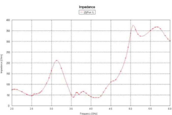
Fig.3 shows the impedance results of the proposed MIMO antenna. From the results we can see that the impedance of the antenna is obtained as 50Ω at 2.40GHz, 3.6GHz and 3.93GHz respectively for source1 and 50Ω at 2.417GHz, 3.6GHz and 3.93GHz for source 2 when they are individually excited. These results are obtained within the operational band i.e. 2.4 to 2.5 GHz with operating frequency as 2.47 GHz.
Fig.3 a) Impedance of port 1 of the proposed antenna
Fig.3 b) Impedance of port 2 of the proposed antenna
Fig.4 VSWR of the proposed antenna
Ajinkya Vekhande et al. Int. Journal of Engineering Research and Applications www.ijera.com
ISSN : 2248-9622, Vol. 5, Issue 4, ( Part -2) April 2015, pp.82-84
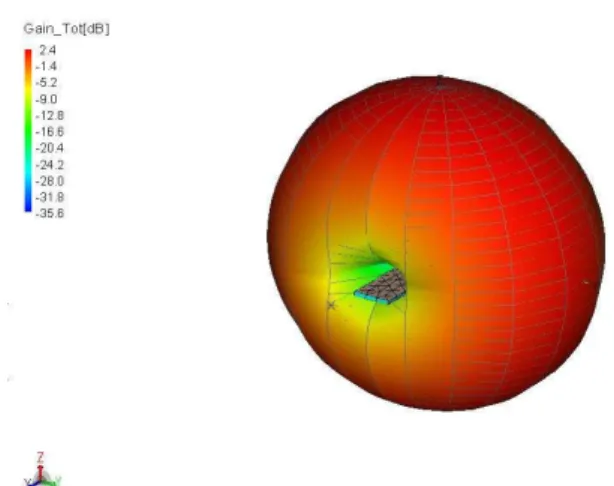
www.ijera.com 84 |P a g e Fig.5 simulated 3D gain pattern of proposed antenna
Fig 5 shows the 3D gain pattern of proposed antenna .The overall (total) gain of proposed antenna is 2.4dB and Fig 6 comprises the directivity of proposed antenna which is found to be 2.5dB in total for proposed antenna.
Fig. 6 Directivity of proposed antenna
Fig 7 shows the efficiency of proposed antenna. At 2.5GHz 96.23% and at 3.74GHz 86.57% efficiency is obtained for proposed antenna.
Fig.7 Efficiency of proposed antenna
IV.
CONCLUSIONA PIFA type MIMO antenna for USB dongle applications operating at WLAN band is proposed and verified. The S11 and S22 based on -10 dB for WLAN are resonated by the two PIFAs. The S21 between the PIFAs, which is achieved by a T shaped element, a neutral line and vertical line is less than -15dB to ensure good isolation. The radiation patterns of the two antennas.
REFERENCES
[1] Wen-Shan Chen and Ke-Ming Lin Fa-Shian Chang “MIMO Antenna with Enhanced Isolation Elements for USB Dongle Applications” Cross Strait Quad-Regional Radio Science and Wireless Technology Conference, 2012
[2] I. J. Gupta, J.A. Ulrey and E. H. Newman, “Antenna Element Bandwidth and Adaptive Array Performance,” Proc. 2005 IEEE AP-S, pp.295-298, 2005.
[3] T. Katajamaki, “A compact dual-band phased array antenna for outdoor WLAN,”
IEEE Vehicular Technology Conference. pp. 59-63,2004.
[4] Z. Li, Z. Du and K. Gong, “A dual-slot diversity antenna with isolation enhancement using parasitic elements for mobile handsets,” Proc.2009 Asia-Pacific Microwave Conf., pp. 1821-1824.
[5] F. G. Zhu, J. D. Xu and Q. Xu, “Reduction of mutual coupling between closely-packed antenna elements using defected ground structure,” Electron. Lett., vol. 45, No. 12, pp. 601-602, June 2009.