Analysis Of Laminated and Sandwich Composites by A Zig-Zag
Plate Element with Variable Kinematics and Fixed Degrees Of
Freedom
Ugo Icardi*, Federico Sola**
*(Dipartimento di Ingegneria Meccanica e Aerospaziale, Politecnico di Torino, Italy) ** (Dipartimento di Ingegneria Meccanica e Aerospaziale, Politecnico di Torino, Italy)
ABSTRACT
A C° layerwise plate element with standard nodal d.o.f. and serendipity interpolation functions is applied to the analysis of laminates and sandwiches giving rise to strong layerwise effects. The element is obtained using an energy updating technique and symbolic calculus starting from a physically-based zig-zag model with variable kinematics and fixed d.o.f. able to a priori satisfy to displacement and stress continuity at the material interfaces. Non classical feature, a high-order piecewise zig-zag variation of the transverse displacement is assumed as it helps keeping equilibrium. Crushing of core is studied carrying apart a detailed 3D modelling of the honeycomb structure discretizing the cell walls with plate elements, with the aim of obtaining apparent elastic moduli at each load level. Using such apparent moduli, a 2D homogenized analysis is carried out simulating sandwiches as multi-layered structures Applications are presented to plates undergoing impulsive loading incorporating plies with spatially variable stiffness properties. It is shown that accurate predictions are always obtained in in the numerical applications with a very low computational effort. Compared to kinematically based zig-zag models, present physically based one is proven to more accurate, being always in a good agreement with exact 3D solutions.
Keywords
– Impulsive loading, Indentation, Hierarchic representation, Optimized tailoring, Stress relaxation, Variable stiffness composites.I.
I
NTRODUCTIONLaminated and sandwich composites are increasingly finding use as they offer the possibility to optimize structural performances by properly choosing fibre orientation and stacking lay-up. These materials are widespread also owing to their high specific strength and stiffness, since they enable construction of structures that achieve the target requirements with the lowest mass possible (see, e.g. Sliseris and Rocens [1]).
Due to their inhomogeneous microstructure, unfortunately, they suffer from critical local stress concentrations that give rise to micro-damage formation and growth in service. Because elastic moduli and strengths in the in-plane direction are much bigger compared to those in the thickness direction, warping, shearing and straining deformations of the normal take place. A recent, comprehensive discussion about the mechanisms of damage formation and evolution and about their modelling is given by Càrdenas et al. [2]. As discussed by Chakrabarti et al. [3], Qatu et al. [4] and Zhang and Yang [5], these so called zig-zag and layerwise effects should be described with the maximal accuracy but with the lowest costs, in order to explore many possible design options with affordable costs.
Composite plate and shell theories and elements have been developed using different approaches. As examples of early theories, the papers by Wu and Liu [6], Cho et al. [7] and Averill and Yip [8] are cited. A review of such theories is presented in the paper by Burton and Noor [9]. An extensive discussion of the various techniques used to account for the layerwise effects and extensive assessments of their structural performances have been recently presented in the papers by Chakrabarti et al. [3], Matsunaga [10], Chen and Wu [11], Kreja [12], Tahani [13] and Gherlone [14]. In particular, accuracy of finite element models is assessed by Chakrabarti et al. [3], Zhang and Yang [5], Shimpi and Ainapure [15], Elmalich and Rabinovitch [16], Dau et al. [17], Feng and Hoa [18], Desai et al. [19], Ramtekkar et al. [20], To and Liu [21]. Zhen et al [22], Cao et al. [23] and Dey at al. [24].
Laminates and sandwiches with laminated faces constructed using automated fibre-placement technology (Barth [25]) whose reinforcement fibres follow curvilinear paths that are obtained using advanced optimization techniques achieve the maximal performance, as shown by Sousa et al. [26] and Honda et al. [27], and contemporaneously can relax critical local stress concentrations, as shown e.g. by Icardi and Sola [28]. Many iterations being
required by the optimization process, the use of efficient structural models that account for the zig-zag and layerwise effects with the minimal processing time and memory storage occupation becomes mandatory. Otherwise a mistaken prediction of these effects could result in inaccurate evaluations of strength, stiffness, failure behaviour and service life.
When a separate representation of layers is used, computational costs can become unaffordable for analysis and optimization of structures of industrial complexity, since the number of variables increases with the number of physical/computational layers. Models and elements based on a combination of global higher-order terms and local layerwise functions have been proven to be equally accurate but with a much lower computational effort (see, e.g. Elmalich and Rabinovitch [16] and the references
therein cited). The Murakami‟s zig-zag function just based upon kinematic assumptions is often used as local layerwise function, but the assessments carried out by Gherlone [14] proven that it is accurate for periodical stack-ups, but not for laminates with arbitrary stacking sequences, or for asymmetrical sandwiches with high face-to-core stiffness ratios, like when a face is damaged.
On the contrary, physically-based zig-zag models have been proven to be always accurate. Refinements have been progressively brought to these models in order to achieve a good accuracy with the lowest computational burden and to successfully treat panels with low length-to-thickness ratio and abruptly changing material properties like sandwiches. To this purpose, sublaminate models having top and bottom face d.o.f. were developed by Aitharaju and Averill [29] and subsequently by other researchers in order to stack computational layers. The displacement field was recast in a global-local form to accurately predict stresses from constitutive equations (see, Li and Liu [30], Zhen and Wanji [31] and Vidal and Polit [32]), because post-processing operations are unwise for finite elements and cannot always give accurate results, as shown by Cho et al. [7]. Of course, sandwiches can be described as multi-layered structures assuming the honeycomb core as a thick intermediate homogeneous layer whenever a detailed description of local phenomena in the cellular structure is unnecessary (see, Phan et al. [33], Gibson and Ashby [34]).
The authors have recently developed a physically-based zig-zag model [35] aimed at carrying out the analysis of multi-layered and sandwich composites having abruptly changing properties with the minimal computational burden.
Its characteristic feature is a high-order piecewise zig-zag representation of the displacements that can be locally refined to obtain accurate stress predictions from constitutive relations, though its
functional d.o.f. are fixed (the classical displacements and shear rotations of the normal at the mid-plane). Accurate results were obtained in the numerical applications with a computational effort comparable to that of equivalent single-layer models, thus considerably lower than for available layerwise models [35]. Symbolic calculus was used to obtain automatically and once for all in closed-form the relations required to a priori satisfy the physical
constraints. In order to describe the core‟s crushing
behaviour of sandwiches, a high-order piecewise zig-zag variation of the transverse displacement was assumed, while usually this is avoided in order to
simplify algebraic manipulations. This
representation also helps keeping equilibrium at cut-outs, free edges, nearby material/geometric discontinuities and to predict stresses caused by temperature gradients (see, e.g. [22] and [36]).
Regrettably, physically-based zig-zag models involve derivatives of the functional d.o.f., which thus should appear as nodal d.o.f. when developing finite elements. Consequently C1 or high-order
representations are required, instead of
computationally efficient C° interpolation functions. Techniques have been proposed for converting derivatives, but they result in an increase of the nodal d.o.f and thus of the memory storage dimension (see, e.g. Sahoo and Singh [37]). The energy updating technique [38] - [41], hereafter referred as SEUPT, originally developed as an iterative post-processing technique to improve the predictive capability of shear deformable commercial finite elements has been revised by the authors in [40] in order to obtain an equivalent C0 version of the zig-zag model [35] by the energy standpoint, which was used to develop an efficient eight node plate element.
impulsive loading, which incorporate plies with spatially variable stiffness properties. The reasons for the choice of these samples cases are as follows.
Many studies investigating the core crushing mechanism have been presented in the literature where often a detailed finite element simulation of the cellular structure of honeycomb is adopted (Aminanda et al. [42]), because only in this way the buckling of cell walls can be accurately described. Solid elements are often used to discretize foam core (Mamalis et al. [43]). Crushing of core is followed by tearing of the loaded face. The topology of cells, their relative density and the thickness of the foil have considerable influence on this behaviour. Sandwiches being used as primary structures need an accurate simulations of these phenomena. However, despite accuracy could not always be maximal, in an industrial environment it is more attractive carrying out the simulations with advanced 2-D layerwise plate elements instead of using 3-D FEA and considering stress-based failure criteria instead of fracture mechanics or cohesive zone models (see, e.g., Panigrahi and Pradhan [44] and Menna et al. [45]), in order to keep affordable the computational
burden. At the authors‟ best knowledge, no applications of last generation of refined zig-zag models and related elements have been still presented to indentation studies, in spite they could speed up simulations, saving computational costs and preserving accuracy.
To accurately describe crushing but with a low cost, in this paper the behaviour of core under transverse loading is determined apart once at a time by a finite element analysis where the cell walls are discretized by the present plate elements. In this way, the variation of the apparent properties of core under transverse loading are determined as apparent elastic moduli that vary with loading. The onset of damage is determined using stress-based criteria, but instead of considering a healthy material, a damaged material is considered at each iteration using the continuum damage mesomechanic model by Ladevèze et al. [46], [47]. This model provides a modified expression of the strain energy that accounts for the effects of the damage on the microscale, then stresses are computed taking into consideration the effects of local damage. The progressive failure analysis is carried out extending a pre-existing damage/failure to the points where the ultimate condition is reached, as predicted by stress-based criteria. Because the properties are assumed to vary with the applied load and from point to point over the contact area, the most relevant local phenomena in the core are considered. Once the apparent elastic properties of core have been determined, the analysis is carried out in 2-D form using elements [40], thus describing sandwiches as multi-layered plates.
As customarily, the indentation depth and the contact area are computed assuming the distribution of the contact force to be Hertzian and the projectile as a rigid body. The contact area is evaluated at any time step using the iterative algorithm by Palazotto et al. [48] that forces the surface of the target to conform to the shape of the impactor, as required by soft media. Because there is an equivalence between static and dynamic results for low velocity impacts, just a static simulation could be carried out.
Nevertheless, the Newmark‟s implicit time
integration scheme is employed to solve the transient dynamic equations, as it was developed to treat general transient dynamic problems of practical interest, as blast pulse loading.
In order to assess the potential advantages that could be obtained using variable stiffness composites, in particular whether a relaxation of critical stress concentrations can be obtained in practical test cases contemporaneously to a maximization of stiffness properties, the optimal property distributions computed by the tailoring optimization technique (OPTI) presented in Ref. [28] are used in the numerical applications. Using OPTI, the optimization problem of variable-stiffness composites turns into a simple problem of finding the appropriate stacking sequence, like with straight-fibre composites, which can be efficiently solved using the classical optimization techniques, because the optimal solution is computed apart once for all in closed or numerical form. As a consequence, a layerwise structural model can be used for having a realistic prediction of the structural behaviour without resulting into a unaffordable computational effort.
II.
S
TRUCTURAL MODELThe displacement field is assumed as the sum of four separated contributions [35]:
0 _
( , , )
, ,
, ,
, ,
, ,
i
c c ip
u x y z
U
x y z
U
x y z
U
x y z
U
x y z
0 _
( , , )
, ,
, ,
, ,
, ,
i
c c ip
v x y z
V
x y z
V
x y z
V
x y z
V
x y z
(1)
0 _
( , , )
, ,
, ,
, ,
, ,
i c c ip
w x y z
W
x y z
W
x y z
W
x y z
W
x y z
whose purpose is explained hereafter. Symbols u, v and w respectively define the elastic displacements in the directions x, y and z of a rectangular Cartesian reference frame with (x, y) on
the middle surface of the plate (Ω) and z normal to it.
A. Basic contribution Δ0
0 0 0 0 ,
( , , ) ( , ) x( , ) x( , )
U x y z u x y z
x y w x y 0 0 0 0
,
( , , ) ( , ) y( , ) y( , )
V x y z v x y z x y w x y (2)
)
,
(
)
,
,
(
0 0y
x
w
z
y
x
W
Displacements u0(x, y), v0(x, y), w0(x, y) and transverse shear rotations γx0(x, y) and γy0(x, y) at the
middle plane represent the five functional d.o.f. of the model (1).
B. Variable kinematics contribution Δi
Contributions with superscript i are variable
kinematic contributions that enable the
representation to vary from point to point across the thickness, in order to refine the model where necessary:
2 3
1 2 3
4 4
( , , )
...
i
x x x
n
x xn
U x y z
A z
A z
A z
A z
A z
2 3
1 2 3
4 4
( , , )
...
iy y y
n
y yn
V x y z
A z
A z
A z
A z
A z
(3)2 3
1 2 3
4 4
( , , )
...
i
z z z
n
z zn
W x y z
A z
A z
A z
A z
A z
The unknown coefficients
A
x1…A
zn arecomputed as expressions of the functional d.o.f. and of their derivatives by enforcing conditions:
0
|
0
|
xz l
u xz
(4)0
|
0
|
u
yzl
yz
(5) l l zz u uzz
|
p
|
|
p
|
0 0
(6)0
|
0
|
,,
zzz l
uz
zz
(7)and the equilibrium at discrete points across the thickness: , , , , , , , , ,
0
0
0
xx x xy y xz z xy x yy y yz z xz x yz y zz z
(8)The symbols (k)z+ and (k)z- were used to indicate the position of the upper+ and lower - surfaces of the kth layer and the superscript(k) the quantities that belong to a generic layer k. A comma was used to indicate differentiation.
The expressions of the unknowns Ax1 … Azn are
obtained in closed-form as functions of the d.o.f. and of their derivatives using MATLAB® symbolic software package, thus they neither results into a considerably larger computational effort, nor into a larger memory storage. Because derivatives are unwise for the development of finite elements, the technique described forward and therein referred as SEUPT will be used to obtain a C° equivalent model.
It could be noticed that unknowns Ax1 … Azn can
be determined also in order to fulfil boundary conditions such as clamped edges. It is reminded that assuming mid-plane displacements and shear rotations as functional d.o.f., when they are enforced to vanish in order to satisfy clamped constraints it automatically results that erroneous vanishing transverse shear stresses could be obtained. The successful application of the model to structures with clamped edges was shown in [35], [41] and [49]. A case will be also shown in this paper (Case B, section VI.B.2).
C. Zig-zag piecewise contribution Δc
These contributions, are assumed in the following form: 1 1 ( , ) ( , )( ) ( , ) i i n c k
x k k
k n
k
u k
k
U x y x y z z H
C x y H
1 1 ( , ) ( , )( ) ( , ) i i n c ky k k
k n
k
v k
k
V x y x y z z H
C x y H
(9) 1 2 1 1 ( , ) ( , )( ) ( , )( ) ( , ) i i i n c k k k k n n k kk k w k
k k
W x y x y z z H
x y z z H C x y H
They are aimed at making the displacements continuous and with appropriate discontinuous derivatives in the thickness direction at the interfaces of constituent layers, in order to a priori fulfil the continuity of interlaminar stresses at the material interfaces. Terms Φxk, Φyk are incorporated in order to
satisfy continuity of transverse shear stresses:
( ) ( ) ( ) ( )
|
|
|
|
k k k kxz z xz z
yz z yz z
(10)while k, k terms enable the fulfilment of continuity conditions: ( ) ( ) ( ) ( ) , ,
|
|
|
|
k k k kz z z z
z z z z
z z
(11)which directly derive from the local equilibrium equations as a consequence of the continuity of transverse shear stresses.
Terms Cu k
, Cv k
and Cw k
restore the continuity of displacements at the points across the thickness where the representation is varied:
z z k k
u
u
z z k kv
zz k
k
w
w
D. Variable in-plane representation Δc_ip
Contributions Δc_ip are incorporated in order to restore continuity when the material properties suddenly change moving along x or y:
_ 1 1 1 1 2 1 1 2 1 1
( , )(
)
( , )(
)
( , )(
)
( , )(
)
...
S Tc ip j k
u x k k
j k S T
j k
u y k k
j k S T
j k
u x k k
j k S T
j k
u y k k
j k
U
x y x
x H
x y y
y H
x y x
x
H
x y y
y
H
(13) _ 1 1 1 1 2 1 1 2 1 1( , )(
)
( , )(
)
( , )(
)
( , )(
)
...
S Tc ip j k
v x k k
j k S T
j k
v y k k
j k S T
j k
v x k k
j k S T
j k
v y k k
j k
V
x y x
x H
x y y
y H
x y x
x
H
x y y
y
H
(13a)The exponent of (x – xk) n
, (y – yk) n
is chosen in order to make continuous the gradient of order n of a stress component of interest. The expressions of all the continuity functions defined above are obtained once for all in a closed form by enforcing the fulfilment of the pertinent continuity conditions (Icardi and Sola [49]).
III.
C0
EQUIVALENT MODEL AND FINITEELEMENT
As well known, energy-based weak form versions of governing equations can be used to construct equivalent forms by the energy standpoint using various techniques. As shown by Icardi [38] and [39], an iterative post-processing technique working on a spline interpolation of results can be developed with the aim of constructing an updated solution that locally improves the accuracy of a finite element analysis by standard shear-deformable plate elements. In this way, accuracy can be improved up to the level of a layerwise model in the most critical regions, with a low computational effort.
The idea can also be used to derive a modified expression of the displacements fields by a structural model, in order to obtain a C0 formulation free from derivatives to use for developing accurate and
efficient finite element models, as shown by Icardi and Sola [39] - [41]. Applications of this technique, hereafter referred as SEUPT, to sample test cases with exact solutions and intricate through-the-thickness stress distributions, have shown that the equivalent model (EM) free from derivatives that is obtained from the consistent model (OM) of Eqs. (1)-(13a) is capable of providing results that are equally accurate, requiring a comparable low computational effort. The steps to develop an efficient finite element plate model with C° interpolation functions and standard nodal d.o.f. from the EM model are the following ones.
Hereon the displacements by the OM model will
be indicated as
u
(
x
,
y
,
z
)
OM,OM
z
y
x
v
(
,
,
)
,w
(
x
,
y
,
z
)
OM, their counterparts representing the equivalent C0 model EM obtained by SEUPT will be indicated asu
(
x
,
y
,
z
)
EM,EM
z
y
x
v
(
,
,
)
,w x y z
( , , )
EMor, in compact form,respectively as
OM and
EM. In a similar way, all quantities by the OM model will be indicated with the superscript OM, while those referring to EM model with the superscript EM.The basic assumption of SEUPT is that postulating displacements
EM as the sum of terms
that are just functions of the d.o.f. and terms
containing all the derivatives of the d.o.f.)
,
,
(
)
,
,
(
)
,
,
(
x
y
z
x
y
z
x
y
z
EM
(14) each term
can be replaced, since its energy contributions can be accounted for incorporatingcorrective terms free from derivatives
u
0,
v
0,0
w
,
x0,
y0 (in compact form
):( , , )
( , , )
( , , )
EM
x y z
x y z
x y z
(14a)thus an equivalent C° version EM of the zig-zag model OM can be obtained by the energy standpoint, which can be used to develop an efficient plate element. The expressions of
are derived from the energy balance, which is written in compact form as:(.) |
(.) |
(.) |
(.) |
0
E Λi Λ f
Λm
(15)its three contributions being the strain energy, the work of external forces and the work of inertial forces, respectively.
principle of virtual work with the inertial forces accounted for, then each of these five contributions is further split collecting apart the single contributions of primary variables multiplying the same virtual displacement. The expressions of corrective terms
are obtained equating each contribution by the OM model to its counterpart by the EM model:
(.)|
(.)|
0 0 0
EM u E OM u E
;
(.)|
(.)|
0 0 0
EM v E OM v E
;
(.)
|
(.)
|
0
0 0
EM w E OM w E
; (16)
(.)|
(.)|
0 0 0
EM E OM E x x
;
(.)|
(.)|
0 0 0
EM E OM E y y
;Previous equations state that whether the consistent displacement fields by the OM model satisfy the energy balance, the modified displacements by the EM model satisfy it too, thus they represent an admissible solution by the energy standpoint. To solve once for all in closed form using symbolic calculus, appropriate spatial distributions of displacements under the same loading and boundary conditions should be postulated.
Assume that the domain Ω is decomposed into small generic quadrilateral subdomains Ω* The variation of the functional d.o.f. inside Ω* is
expressed through Hermite‟s polynomials, since they represent the right interpolation scheme for developing a conforming element from the OM model. At least products of 5th order Hermite polynomials in x and y should be assumed because at least third-order derivatives in x, y are involved by
the OM model. A regular solution is obtained in Ω by the superposition of solutions within subdomains Ω*
because the Hermitian interpolation makes continuous the d.o.f. and their derivatives across adjacent subdomains. The purpose of SEUPT is to find a C0 formulation represented by the equivalent EM model that allows for a computationally efficient Lagrangian representation, thus this type of representation is adopted in Eqs. (16) for the EM model. Because the continuity of displacement derivatives and stresses at sides and vertices of subdomains cannot be satisfied by the Lagrangian interpolation, it should be preliminary enforced in the OM model while computing terms Δc_ip of Eqs (13), (13a).
Because the EM model is just equivalent form the energy standpoint to the OM model, it only provides a correct solution in terms of displacement d.o.f. at any point, thus all the derived quantities like stresses should be computed by the OM model. Because expressions are obtained once for all via symbolic calculus, all updating operations and the computation of stresses are carried out in a very fast
way requiring a very low computational effort in the numerical applications.
At this point, an efficient displacement-based, isoparametric C° plate element can be developed using standard techniques [39]. Because no derivatives are involved as nodal d.o.f., the vector of nodal unknowns can be assumed as:
Q
0 0 0 0
1 1 1 1 1 2 2 2 2 2
0 0 8 8 8 8 8
, , ,
,
* ,
, , ,
,
*,....,
, , ,
,
*
o o o o o o
x y x y
T
o o o
x y
u v w
u v w
u v w
(17)(See inset in Figure 3). Consequently, standard serendipity Lagrangian interpolation functions can be used. At corners nodes (1, 2, 3, 4) they are expressed as:
1 1
0
1
(1 )(1 ( 1) )( ( 1) 1)
4
i i
i i oi oi oi
N (18)
while at mid-side nodes (5, 6, 7, 8) they are expressed as:
2
5 5 05
2
6 6 06
2
7 7 07
2
8 8 08
1
(1
)(1
)
2
1
(1
)(1
)
2
1
(1
)(1
)
2
1
(1
)(1
)
2
o o o oN
N
N
N
(19)Such a parabolic representation is chosen in order to obtain accurate results with a relatively coarse meshing, because accuracy of isoparametric four node quadrilateral elements can be too poor, as shown in the literature. It is reminded that no post-processing operations like integration of local differential equilibrium equations are required, since the stresses are accurately computed by the OM model from constitutive equations.
As customarily, mapping is used to standardize the computation of energy integrals, obtaining a square element with unit sides from any quadrilateral element in the physical plane
8 1 i i iN
x
x
and
8 1 i i iN
y
y
(20)This isoparametric formulation allows to efficiently compute the Jacobian matrix
y
x
y
x
J
]
which is required to obtain the physical derivatives
x
,y
from the derivatives
,
over the natural plane
1J
y
x
(22)The stiffness matrix is computed from the strain energy functional in the standard way as:
dV
B
D
B
K
Ve T]
][
[
]
[
]
[
(23)the strains in infinitesimal form here considered being expressed as:
{
}
}
{
B
Q
(24) and the stresses as:
{
}
}
{
D
B
Q
(25)
D
being the matrix of 3D elastic coefficients,Ve
and the volume of the element.The mass matrix is obtained from the kinetic energy functional as customarily:
dV
N
N
M
Ve T]
[
]
[
]
[
(26)
being the density. The vector of nodal loads is evaluated from the expression of the work of external forces in the standard way as:
[ ] [ ] [ ] T Ve T T SeFe N X dV
N f dS N F
%(27)
X
being the vector of body forces,
f
the vector of surface forces applied on the surfaceSe
and
F
~
the point forces. Integrations are carried out using a 3x3 Gaussian integrations scheme, since selective reduced integration is unnecessary because locking is avoided by a suited choice of coefficients Δi of the EM model and as a consequence of the present choice of the nodal d.o.f., since bending and transverse shear contributions are kept separated. The integrals are carried out summing up the contributions layer-by-layer when multilayered structures are considered.IV.
M
ODELLING OF LOADING ANDDAMAGE
In this section, the techniques used for modelling blast pulse loading, the failure behaviour and indentation are overviewed.
A. Pulse pressure loading
When a pressure pulse is generated, a shock wave is transmitted in all directions. Once it reaches a structure, it creates a pressure wave characterized by an instantaneous pressure peak followed by a decrease as time folds. Research studies looking for configurations able to reduce the detrimental effects of such loading have been carried out by Gupta [50], Gupta et al. [51], Song et al. [52], Librescu et al. [53], [54] and Hause and Librescu [55] considering the overpressure
P
z(
t
)
uniformly distributed over the whole panel, the front of the explosive blast pulse being supposed to be far, and its time variationexpressed by Friedlander‟s exponential decay
equation in modified form as:
tpt a p m z
e
t
t
P
t
P
(
)
1
(28)m
P
being the overpressure peak,t
p the positivephase duration of the pulse measured from the time of impact and
a
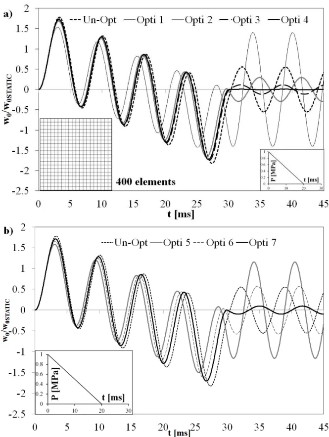
a decay parameter that is adjusted to approximate the pressure curve from the results of a blast test. A linear variation with an initial positive pressure peak that decays till to end with a negative pressure at the end of the overpressure phase is often considered in the numerical simulations to represent the sonic boom. Triangular, rectangular, step and sinusoidal pressure pulses are also often used, which are obtained as a particular case of previous equation. When the pressure pulse is idealized in this way, delay to pressure wave arrival, duration of pressure and maximum pressure are the parameters involved, which depend upon the offset distance between the point of explosion and the centre of the panel.As refined structural models based on a combination of global higher-order terms and local layerwise functions like the present one were not considered in these studies, whether or not accurate modelling of layerwise and zig-zag effects can imply a considerable variation of results, i.e. a considerable mutation of best configuration able to resist to loading, still remains an open question that the present paper is aimed at contributing to discuss. To this purpose, sample cases presented in the literature will be retaken and analysed with the present structural model.
B. Solution of dynamic equations.
(29) are solved using Newmark implicit time integration scheme, {D} being the vector of the nodal d.o.f. for the whole structure and {P(t)} the vector of nodal loads. Such solution scheme is chosen to solve the transient dynamic problem since explicit time integration is advantageous just when extremely strong geometric and material non-linearity are considered. This being not the present case, and since an explicit scheme need extremely small time steps to be stable, an implicit scheme was chosen. Accordingly, solution to Eqs. (29) is found representing the velocity and the acceleration vectors
after a time step Δt as:
(30)
By substituting the expressions of Eq.(30) into Eq. (29), a linear algebraic solving system of the type F(Dn+1) =0 is obtained. In order to be unconditionally
stable, the Newmark algorithm requires β ≥ ≥ 0.5 (see, e.g. Ref. [28]). Aiming at meeting stability requirements, the calculations are carried out
considering =1/4 and =1/β, while for limiting
convergence and rounding errors, relatively small time-steps are considered in this paper.
C. Indentation of sandwiches with honeycomb core
Because homogenized models cannot properly treat these collapsing mechanisms, a discrete modelling of honeycomb core giving a detailed representation of the real geometry is required. As microbuckling and local failure of core are highly mesh sensitive [56], a very refined meshing is required and a self-contact algorithm should be used to prevent from interpenetration between the folds in the cell walls.
In this paper a detailed, preliminary finite element analysis (PFEA) is carried apart once for all in order to compute the apparent elastic moduli of the core while it collapses/buckles under transverse compressive loading. In this phase, the present plate element is used to discretize the cell walls. An elastic-plastic behaviour [56] of the material constituting honeycomb walls is considered. The updated Lagrangian methodology is used to efficiently account for geometric nonlinearity.
Once the variable apparent elastic moduli are computed (as the tangent moduli derived from the average ratio of stresses and strains) the analysis is carried out in homogenized form by discretizing the sandwich panel as a multi-layered structure whose properties vary with the magnitude of indentation load and with position, as calculated by the PFEA phase. In this phase, geometric nonlinearity effects are accounted for still using the updated Lagrangian method. This approach is chosen since the discrete modelling of honeycomb may determine overloading computations when simulating structures of industrial complexity. The objective of numerical test will be that of assessing whether such modelling of the crushing behaviour of cells can be carried out separately from the homogenized analysis of the whole structure without a remarkable accuracy loss, in order to speed-up computations, as illustrated in Section VI.B.
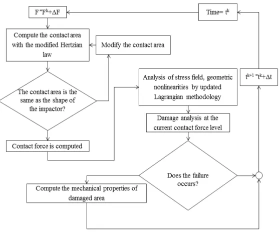
As customarily, the indentation depth, the contact area and the contact stress are computed assuming the distribution of the contact force to be Hertzian. The projectile is described as a rigid body, while the nonlinear effective stiffness of the target structure, as it results by the finite element model including the plate stiffness and the contact stiffness, is employed for solving the contact problem. Non-classical feature, the contact radius and the applied pressure corresponding to the load are computed at each load step using an iterative algorithm (see, Palazotto et al. [48]) that forces the top surface of the target, i.e. the sandwich panel, to conform the shape of the impactor (in the least-squares sense) , the core being a soft media. At each time step, the contact radius is computed within each load step varying the displacements till the impacted top surface conforms to the shape of the impactor. The contact area radius computed at each load step is assumed as the estimated contact radius R contact for the next
increment of load, which is used to compute the contact force according to the Hertzian law:
2 2
/
1
)
0
(
)
(
r
r
R
contact
(
(
r
)
0
ifr
R
contact) (31)Initially, i.e. at the first time increment Δt, the contact force is assumed to reach the value F=ΔF and no damage is assumed to occur. The load is then iteratively incremented within the time-step, the contact area radius computed at each load step being assumed as the estimated contact radius for the next increment of load. The contact force F and the vertical displacement are computed when the shape of the target conforms to that of the impactor. In this way, the impactor moves on at a distance that depends upon the effective nonlinear stiffness of the panel. The damage is computed at each new time step as outlined forward, using the contact radius computed at the end of the previous load-step. The load is then incremented and the process repeated at the next time step till the impactor and the indentation radii are in agreement, then the failure analysis is performed again. Because the solution depends on the current configuration and previous history, the Newton-Raphson method is used to solve the contact problem. The residual force Ri is
computed employing the secant stiffness matrix, the load at the next iteration F(i) and the solution at the
previous iteration q0(i-1), as customarily. The tangent
stiffness matrix is used to evaluate the updated solution that makes the structure in equilibrium from the residual force balance. (see Figure 1)
Nevertheless there is a general agreement that for indentation studies there is a substantial equivalence between static and dynamic results, dynamic equations were solved in order to have the maximal accuracy, so to ascribe eventual discrepancies with reference solutions just to the present modelling approach.
D. Damage and failure
Stress-based criteria with a separate description of the various failure modes are here used to estimate the onset of the damage, as being simple enough and
just requiring use of “engineering” variables they are suited to develop an efficient computational model. A mesoscale damage model is then employed for estimating the residual properties of the failed regions.
1) Onset of damage
The 3-D Hashin‟s criterion with in-situ strengths is chosen to predict the fibre‟s failure and the failure of the matrix. Tensile failure of fibres
(
11
0
)
occurs if:
1
1
2 13 2 12 2 13 12 211
S
X
t (32)t
X
being the tensile strength of fibres,S
1213 thein-situ shear strength of the resin and
11,
12,
13 thetensile and shear stresses acting on the fibres, while compressive failure
(
11
0
)
of fibres occurs if:c
X
11
, (33)c
X
being the compressive strength of fibres. The matrix failure under traction(
22
33
0
)
is ruled by:2
2 22 33
23 22 33 2
23
2 2
13 12
12 13 12 13
1
(
)
1
tY
S
S
S
(34)while under compression
(
22
33
0
)
by:2
22 33
23
2 2
22 33 23 22 33
2 2 23 23 2 2 12 13 2 12 13
1
1 (
)
2
(
)
(
)
4
(
)
1
c cY
Y
S
S
S
S
(35)The Choi-Chang‟s criterion is employed to predict the onset of delamination, which takes place if:
2 1 1 1 1 2
n i n yy n i n xz n i n yz a dY
S
S
D
e
>1 (36)where 1
tn1 nY
Y
if
yy
0
, or1
1
nc n
Y
Y
if0
yy
,D
a is an empirical constant that is set after consideration of the material properties,
ijisthe average stress at the interface between the nth ply and the n+1th ply, computed as follows:
dt
h
n n t t ij n n ij
1 11
1
(37)The subscript‘i‟stands for in situ, while‘t‟ and
„c‟stand for traction and compression, respectively. This criterion disregards the transverse interlaminar stress 33 , but numerical tests in literature have
shown that such omission is not relevant in the majority of cases, thus accurate estimations are usually obtained.
core n lu yz n lu xz n cu
zz
e
(38)to predicts failure, which occurs when
e
core
1
,cu
and
lu being the core strengths in compression and transverse shear. Numerical test in literature have shown that varying the exponent from 1 to 2 no remarkable effects appears on the results of sandwiches with laminated faces, but n = 1,5 best fitted the experimental results, thus this value was chosen. The criterion by Lee and Tsotsis [58] predicts indentation failure to occur at the loading magnitude at which one of these inequalities is verified:1
,
1
,
1
yzyx xz c zz
S
S
Z
(39) cZ
,S
x,S
ybeing the compressive yield strength and the out-of-plane shear strengths, respectively. The criterion by Petras and Sutcliffe [59] predicts indentation failure when:1
)
(
S
Z
yz xz czz
(40)
S
being the transverse shear strength.2) Residual properties
The mesoscale damage model by Ladevèze et al. [47] is chosen for accurately computing the residual properties of failed structures, considering that this model and the other ones of the same class are known for being accurate and computationally more advantageous than structural scale models assuming cracks as hard discontinuities.
The discretely damaged medium is replaced with a continuous homogeneous medium, which is equivalent from an energy standpoint, whose strain energy expression incorporates damage indicators that are computed as the homogenized result of damage micro-models and have an intrinsic meaning. These damage indicators establish the link with the micro-degradation variables, namely they provide the relations giving the new elastic properties of the homogenized damaged model.
The homogenized potential energy density of a single layer assumed as the generic ply S is expressed as: (41) 13 23 12 22
,
I
,
I
,
I
I
andI
33 being the five damageindicators defined as the integral of the strain energy of the elementary cell for each basic residual problem under the five possible elementary loads in the directions 22, 12, 23, 13,33. In the former equation
]
[
M
1 ,[
M
2]
,[
M
3]
represent operators thatdepend on the material properties,
S
is thedeformation, while
.
represents the positive part operator. Eq. (41) features an equivalent state of damage on the mesoscale that is approximately intrinsic for a given state of micro-degradation.Homogenization of the interface
j leads to the following expression of the potential energy density:
(42)
1
~
k
, 2~
k
andk
~
3 being the elastic stiffness coefficientsof the interface,
I
1,I
2 andI
3 the three damage indicators and
j the deformation.It is remarked that equations (41) and (42) are derived making the potential energy stored in the plies and in the interfaces the same as in the micromodel. In this way, a continuum damage model is constructed that is quasi-equivalent from an energy standpoint to the damage micro-model.
Solution is obtained as the sum of the solution of
a problem
P
~
in which damage is removed and the solution of a residual problemP
where a residual stress is applied correcting the undamaged solution around each damaged area.In the present paper, the residual problems for determining the expressions of damage indicators are solved numerically via 3D FEA discretization [60]. Once the damage indicators are computed, the expression of the strain energy is modified according to Eqs. (41), (42). Stresses are evaluated, then the failure criteria described in section IV.D.1 are used (at each time step in dynamic problems) to determine actual failed regions. In this way, the failure criteria are applied at any time step considering the materials damaged as in the reality.
guessing factors for degrading the elastic properties of the failed regions like with the ply-discount theory.
V.
V
ARIABLE-
STIFFNESS COMPOSITESDistributions of stiffness properties that minimize the energy absorbed involving out-of-plane strengths and, contemporaneously, that maximize the one absorbed by modes involving in-plane strengths are considered.
Such distributions are obtained once for all in closed or numerical form as variable ply angle distributions by solving the Euler-Lagrange equations obtained imposing extremal the in-plane, bending and out-of-plane shear contributions to strain energy under spatial variation of the stiffness properties [39], [41].
These candidate solutions represent in-plane variable-stiffness distributions making maximal or minimal the bending stiffness and increasing or decreasing interlaminar stresses, respectively. As a result, OPTI acts as an energy “tuning” procedure that transfer the incoming energy from out-of-plane critical modes to non-critical membrane ones (since laminates and sandwiches have larger strength and stiffness in the in-plane direction than in the thickness one), preserving a high bending stiffness. This non-classical optimization technique consists of the following steps.
First, the strain energy of the structural model is recast in a form that puts in evidence all terms
MN
function of elastic properties and of coefficients containing powers ofz
, which, once integrated across the thickness, define the stiffness properties of the model.
(.)
|
i
=
1
1
k k
z T
nl
ij MN ij MN
k z
d dz
(43)Then, the first variation of former equation under variation of the stiffness properties is constructed, its vanishing enforced and the contributions of each functional d.o.f. are split apart (integration by parts) since the stationary conditions must hold irrespectively of the displacements
H
D d
(44)[H] being a matrix containing the derivatives of
the stiffness coefficients and {δD} the column vector collecting the first variation of functional d.o.f. The contribution multiplying terms δw(0) is here referred as the strain energy due to bending, while the ones
multiplying
x0 , 0
y
are referred as the strain energy due to transverse shears. Since contributions multiplyingu
0 andv
0 are disregarded in theextremization process, as they represent in-plane uninteresting constraints a transfer of energy to
in-plane mode being non-critical, just variations
w
0,0
x
,
0y require a simultaneous solution:3j
0;
4j0;
5j0
H
H
H
(45)The spatial stiffness property distributions that make extremal the bending and transverse shear energy contributions are obtained solving the system of partial differential equations represented by (45) in terms of the stiffness properties, then finding appropriate ply-angle variations in closed or numerical form. The form of solutions is determined by the order of spatial derivatives of the stiffness coefficients in x, y. The present structural model gives rise to following variation of stiffness coefficients as general solution:
1
1
1 2
1 2
1
x y
n n
ij P
px py
ij ij
p x i y
p
Q
A e
k
A e
k
(46)(ij=11, 12, 13, 16, 22, 23, 26, 36, 44, 45, 55, 66). The unknown coefficients
A
1ijp,A
2iji, p, 1
xn, 1
yn, kx, kyare determined by enforcing conditions that determine whether the solution minimises or maximises the strain energy components, such as the stiffness at the bounds of the domain and a convex or a concave shape, as well as the thermodynamic constraints since the solution should be physically consistent.
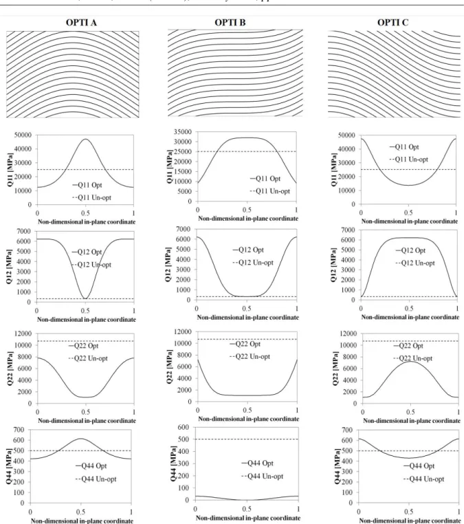
Differently to former applications of the technique, here also the stiffness coefficients, Q44,
Q45 and Q55 are assumed to vary. However, their
variation is very limited compared to the other coefficients as it will be shown forward, thus considering them as constants does not determine significant errors. If the properties of core are optimized across the thickness, the form of solutions is determined by the order of derivation in z and still has a similar general form like (46).
In the numerical applications, sub-optimal polynomial distributions
Gg
g g g g
ij
A
x
B
y
Q
1
will be considered,
because they can be easily obtained with currently available automated fibre-placement manufacturing technologies. The numerical results will show how such sub-optimal stiffness distributions can be effective.
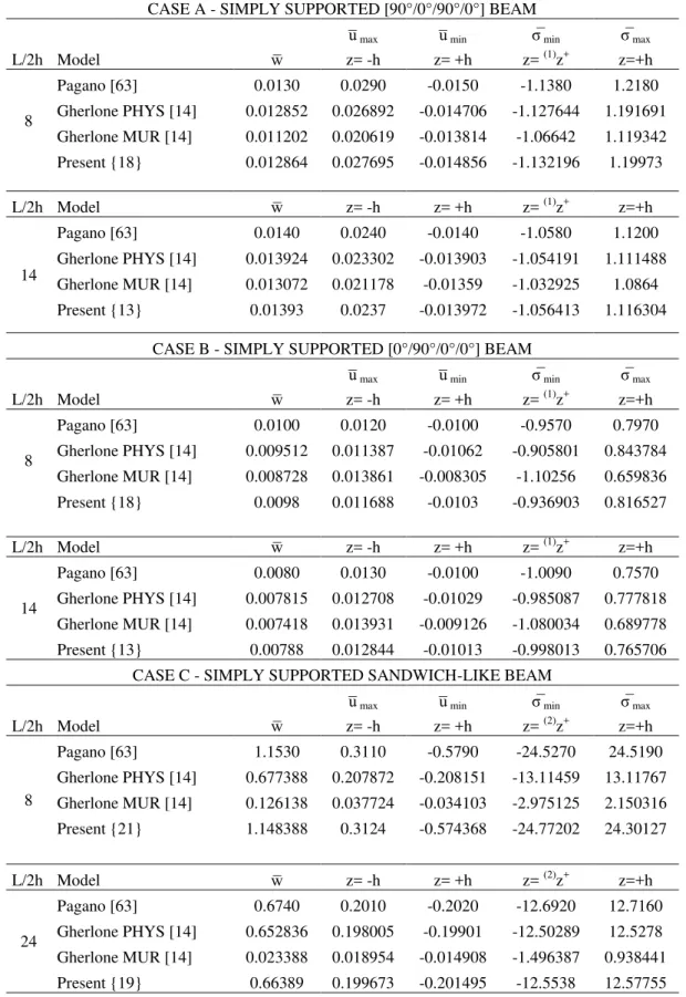
![Table 1 reports a comparison of the results by the present finite element model with analytical solutions by other researchers [14] and with the exact elasticity solution [63], for several different cross-ply schemes and a sandwich-like structure](https://thumb-eu.123doks.com/thumbv2/123dok_br/18299611.347525/13.892.464.782.247.474/comparison-analytical-solutions-researchers-elasticity-solution-different-structure.webp)
![Figure 3. Comparison beetween solution by Pagano [63] (exact) and by the present model for a laminated [0°/90°/0°] plate: a) normalised transverse shear stress σ̅ xz ; b) normalised in-plane stress σ̅ yz](https://thumb-eu.123doks.com/thumbv2/123dok_br/18299611.347525/26.892.110.784.136.1021/figure-comparison-beetween-solution-laminated-normalised-transverse-normalised.webp)
![Figure 4. Comparison beetween solution by Pagano [63] (exact) and by the present model for a laminated [0°/90°] beam: a) normalised transverse shear stress; b) normalised in-plane stress; c) normalised transverse](https://thumb-eu.123doks.com/thumbv2/123dok_br/18299611.347525/27.892.111.785.135.558/comparison-beetween-laminated-normalised-transverse-normalised-normalised-transverse.webp)
![Figure 7. Crushing behaviour for an aluminium honeycomb by Aminanda et al. [42] (experiment) and by the present element](https://thumb-eu.123doks.com/thumbv2/123dok_br/18299611.347525/29.892.122.777.139.581/figure-crushing-behaviour-aluminium-honeycomb-aminanda-experiment-present.webp)
![Figure 9. Comparison between experimental force-indentation curves by McQuigg [68] and by the present finite element for sandwich square panel with a) 3PCF honeycomb and b) 6 PCF honeycomb](https://thumb-eu.123doks.com/thumbv2/123dok_br/18299611.347525/30.892.112.783.139.1021/figure-comparison-experimental-indentation-mcquigg-sandwich-honeycomb-honeycomb.webp)