Different FPR post-strengthening techniques have been developed and applied in existing structures aiming to increase their load capacity. Most of the FRP systems used nowadays consist of carbon ibers embedded in epoxy matrices (CFRP). Regardless of the advantages and the good results shown by the CFRP post-strengthen technique, experimental studies show that, in most cases, the failure of post-strengthened structures is premature. Aiming to better use the tensile strength of the carbon iber strips used as post-strengthening material, the application of prestressed CFRP strips started to be investigated. The main purpose of this paper is to analyze the effects of the composite prestressing in the performance of the CFRP post strengthening technique. The experimental program was based on lexural tests on post-strengthened reinforced concrete beams subjected to static – part 1 and cyclic – part 2 loading. Experimental results allowed the analysis of the quality and shortcomings of post-strengthen system studied, which resulted in valuable considerations about the analyzed post-strengthened beams.
Keywords: prestressing, FRP, strips, carbon iber, concrete structure, fatigue.
Diferentes técnicas de reforço que utilizam sistemas PRF formados com ibras de carbono envolvidas em matriz epoxídica (PRFC) têm sido aplicadas em todo o mundo em estruturas que necessitam aumentar recuperar sua capacidade resistente. Apesar dos bons resultados obtidos e das vantagens associadas a estas técnicas, estudos experimentais mostram que a ruptura das estruturas reforçadas freqüentemente acontece de forma prematura, sem o esgotamento da capacidade resistente do PRFC. Recentemente, a utilização de PRFC protendidos começou a ser investigada, visando a um melhor aproveitamento da resistência à tração dos laminados de ibra de carbono. Dentro deste propósito, este artigo busca analisar a eiciência da técnica de protensão de compósitos laminados, através da realização de ensaios à lexão com carregamento estático – parte 1 e cíclico – parte 2. Os resultados obtidos possibilitaram a análise das qualidades e fraquezas do sistema de reforço estudado, permitindo a obtenção de considerações relevantes sobre as estruturas reforçadas estudadas.
Palavras-chave:protensão, PRF, laminados, ibra de carbono, estruturas de concreto, fadiga.
Post-strengthening of reinforced concrete
beams with prestressed CFRP strips
Part 2: Analysis under cyclic loading
Reforço de vigas de concreto armado
com laminados de PRFC protendidos
Parte 2: Análise sob ação de carregamento cíclico
M. R. GARCEZ a [email protected]
L. C. P. SILVA FILHO b [email protected]
URS MEIER c [email protected]
a Dra., Federal University of Pelotas (UFPel), [email protected], Engineering Center, Pelotas – RS, 96010-900, Brazil.
b PhD., Laboratory of Testing and Structural Modeling (LEME), Departament of Civil Engineering, Federal University of Rio Grande do Sul,
[email protected], Osvaldo Aranha 99, Centro, Porto Alegre - RS, 90035-190, Brazil.
c Doctor Honoris Causa, EMPA, Dübendorf, Suíça.
Abstract
1. Introduction
This paper shows the results of an experimental program de
-veloped at LEME-UFRGS, in Brazil, and at EMPA, in Switzer
-land, regarding the application of CFRP post-strengthening on concrete structures. Continuing the results of the first part of this paper, this second part analyses the behavior of con
-crete beams post-strengthened with prestressed CFRP under cyclic loading.
2. Post-strengthened elements submitted
to cyclic loading
Fatigue may be deined as a permanent and progressive dam
-age process that induces gradual and cumulative crack growth and might, ultimately, result in the complete fracture of the ele
-ments subjected to cyclic loads, if the stress variation and the number of load cycles are large enough. This term was estab
-lished by the irst researchers of the theme due to its nature: a progressive damage process caused by cyclic loads, dificult to observe, that changes the ultimate capacity of the material [Menehhetti et al. [1]].
The usual fatigue failure mechanism for post-strengthened RC beams, when subjected to cyclic loads, is marked by the rupture of one of the steel rebars, followed by a stress redistribution that overloads the remaining bars.
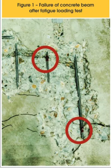
Meier U. [2] highlights that the steel rebars fail before the FRP post-strengthening, as can be seen in Figure [01] that shows the steel rebars of a post-strengthened concrete beam after a fa
-tigue failure. However, cyclic loads can also damage the adhe
-sive and affect the interface concrete-adhe-sive and adhe-sive- adhesive-FRP, leading to premature failures.
According to Ferrier et al. [3], the performance and the durabil
-ity of a concrete structure post-strengthened with FRP, when subjected to cyclic loads, depends not only on the FRP fatigue behavior but also depends on the interface concrete-adhesive and adhesive-FRP.
Authors point out the importance of understanding the behav
-ior of these materials under cyclic loading, since a typical re
-inforced concrete highway bridge deck with a design life of 40 years may experience a minimum of 58x108 loading cycles of
varying intensities.
3. Experimental program
3.1 Description of specimens
Aiming to analyze the behavior of concrete beams post-strength
-ened with prestressed CFRP strips, under cyclic loading, three
Figure 1 – Failure of concrete beam
after fatigue loading test
Table 1 – Description of Experimental Program
Beam
Post-strengthening
Test
Prestressing level
applied on the
strips
Stress range of
fatigue loading*
VFC_PE_01
Two CFRP
prestressed strips
Bending
static loading
35% of e
fu-VFC_PC_01
Bending
ciclic loading
50% to 80%
VFC_PC_02
50% to 60%
beams were tested: one of them was tested under static loading (VFC_PE_01) and two were tested under cyclic loading (VFC_ PC_01 and VFC_PC_02). A complete description about the con
-crete beams, the post-strengthening and the anchorage system used may be found at the irst part of this paper.
Table [01] describes the experimental program.
Stress levels applied at beam VFC_PC_01 were 50% and 80% of the yielding stress observed at beam VFC_PE_01, tested under static load
-ing. Stress levels applied at beam VFC_PC_02 were more reasonable, 50% and 60% of the yielding stress observed at beam VFC_PE_01.
3.2 Test procedure
The experimental program was developed at EMPA – Switzer
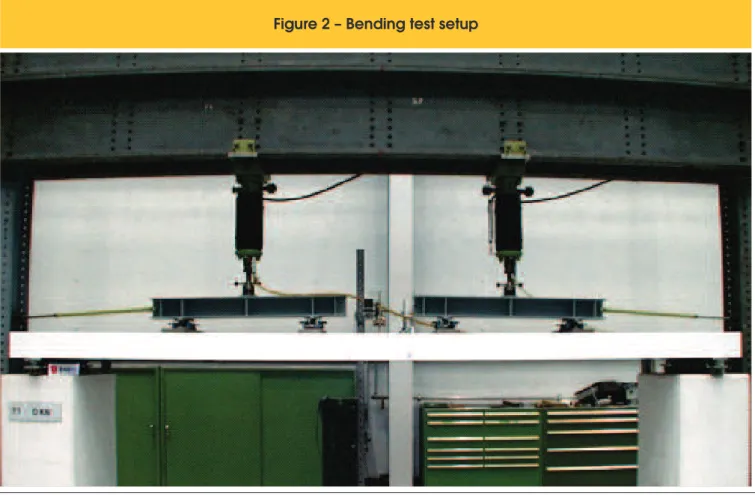
-land. Loading was applied according to a six point bending test scheme: simple supported beam and four vertical loads, spaced by 12000mm, symmetrically applied along the 6000mm span. Load was applied by two 100kN hydraulic jacks. During the tests, values of delection at mid-span and speciic strain at steel, concrete and FRP were continuously recorded by a computer controlled data acquisition system. Bending test setup is shown in Figure [02].
4. Results and discussion
4.1 Results of beam VFC_PC_01
Beam VFC_PC_01 was submitted to stress levels of 50% and 80%
Figure 2 – Bending test setup
reached. When the irst strip debonded, the sudden release of the pre-tensioning force caused a compressive failure at the CFRP, as a secondary failure (Figure [03]).
The secondary failure occurred in a region that was damaged due to the presence of the lexural crack showed in Figure [03], which reached about 90% of the cross-section. Figure [04 (b)] shows one of the CFRP strips after the failure of the post-strengthened beam.
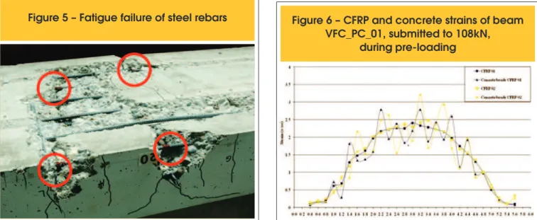
Flexural crack showed in Figure [03] induced the identiication of a steel rebar broken due to fatigue. After the test, the concrete was removed from the bottom of the beam and all steel rebars were inspected. Figure [05] conirms the existence of more steel rebars broken also due to fatigue.
Figures [06] and [07] show strains in the concrete and in the CFRP strips, obtained by deformeters, which gauge points were placed of the yielding stress observed at beam VFC_PE_01, tested under
static loading. Maximum and minimum applied loads were, respec
-tively, 80kN and 40kN, which, added to the self weight, 28 kN, resulted applied loads of 108kN and 68kN (66% and 42% of the ultimate capacity of beam VFC_PE_01)
Aiming to produce the irst cracks, beam VFC_PC_01 was irst pre-loaded up to108kN. Then, cyclic loading was applied at a fre
-quency of 4Hz.
When 282.000 cycles were reached, a crack of about 2,2mm was observed, approximately at mid-span, reaching about 90% of the cross-section. After 331 300 cycles the machine automati
-cally stopped, when the delection limit was reached. It was not observed any sign of apparent failure at the strips. Larger displace
-ment limits were settled and the test was restarted. However, the post-strengthening failed before the maximum load of 108kN was
Figure 4 – Failure of post-strengthening strips: (a) Next to a flexural crack; (b) Distant from flexural cracks
A
B
Figure 5 – Fatigue failure of steel rebars
Figure 6 – CFRP and concrete strains of beam
VFC_PC_01, submitted to 108kN,
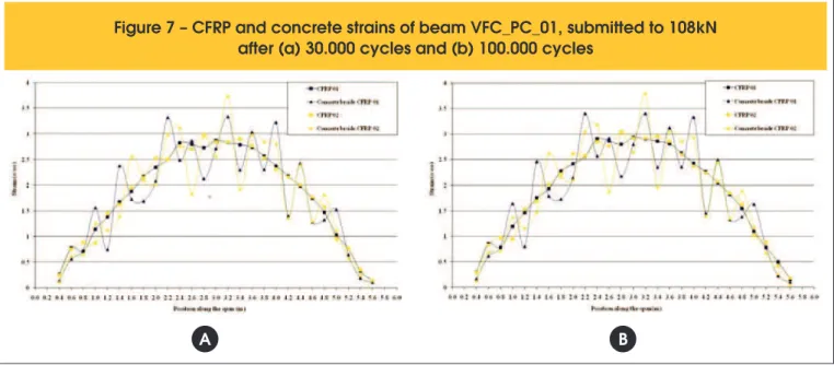
along the bottom of the beam. Measurements were made during pre-loading, after 30.000 cycles, and after 100.000 cycles, with the beam subjected to the maximum load (108kN).
Figures [06] and [07] also shows that the measurements made in the CFRP strips allowed the construction of a well deined curve. Howev
-er, due to the crack growing between the gauge points, this behavior could not be observed in the measurements made in the concrete. Nevertheless all obtained responses followed an expected pattern. Strains in the CFRP strips, at mid-span, during pre-loading, varied
from 2,00º/oo up to 2,50º/oo. At the end of 30.000 cycles, strains
increased to levels that varied from 2,50º/oo up to 3,00º/oo. From
30.000 cycles up to 100.000 cycles, it was not observed any sig
-niicant variation in the strains.
Strains measured, added to the strain applied to prestress each strip
(5,95º/oo), give for each strip a total strain of of 8,45º/oo and 8,95º/oo.
It is also noted that, at mid-span, where most of the cracks could be found, strains measured in the concrete and in the FRP are quite different. It happens because the FRP strip acts as a belt, blocking the concrete crack opening. Therefore, it can be observed that several points along to the beam are subjected to different strains. Such points can, eventually, be related to the occurrence of premature failures.
Strains at a distance of 1.2 m from both beam ends, out of the loading region, are not greater than 1,50°/oo, however, these values
increased about 100% from preloading up to 100.000 cycles. Figure [08] shows the strains in the CFRP strips measured dur
-ing pre-load-ing, after 30.000 cycles and after 100.000 cycles. Sig
-niicant variations were not observed in the range from 30.000 to 100.000 cycles. However, strains increased about 0,50º/oo from the
pre-loading up to 10.000 cycles.
after (a) 30.000 cycles and (b) 100.000 cycles
A
B
Figure 8 – CFRP strains of strip 01 (a) and 02 (b) of beam VFC_PC_01 during cyclic loading
Figure [08] also shows that up to 100.000 cycles the behavior of both strips is similar. However, some variations can be observed at mid-span, due to the high cracking.
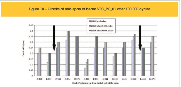
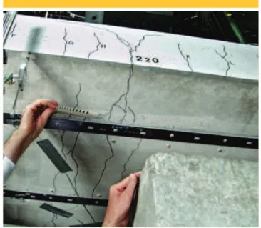
The strategy adopted to monitor the crack growing at mid-span of beam VFC_PC_01 can be observed at Figure [09]. Results of crack openings and the respective position from the left end of the beam are shown in Figure [10].
A high concentration of cracks can be observed at the mid-span of beam VFC_PC_01, between the four loading points. Figure [10] shows the crack openings at mid-span between the two central loading points (signaled on the igure by two vertical arrows). It is noteworthy that, before 100.000 cycles, crack openings did not reached 0,05mm.
The highest crack opening after 100.000 cycles, named D, was 0,4mm, located 254cm from the left side of the beam. However,
apparently the post-strengthening failed due to a 2,2mm crack opening, named I, after 331.300 cycles. It is important to notice that, after 100.000 cycles, this crack opening was about 0,3mm (Figure [11]).
The decision of testing beam VFC_PC_01 under a high stress vari
-ation led to the fatigue failure before 5.000.000 cycles, that was considered the pattern of ininite fatigue life. Stress levels applied to the beam VFC_PC_02, however, are more consistent with the ones usually found in real structures. Results of beamVFC_PC_02 will allow a more detailed analysis of the CFRP prestressing tech
-nique used, as well as of the gradual anchorage system.
4.2 Results of beam VFC_PC_02
Beam VFC_PC_02 was submitted to stress levels of 50% and 60%
Figure 9 – Cracks at mid-span of beam VFC_PC_01 after 100.000 cycles
of the yielding stress observed at beam VFC_PE_01, tested under static loading. Maximum and minimum applied loads were, respec
-tively, 50kN and 40kN, which, added to the self weight of 28 kN, resulted in applied loads of 78kN and 68kN (48% and 42% of the ultimate capacity of VFC_PE_01).
Aiming to produce the irst cracks, beam VFC_PC_02 was pre-loaded up to78kN. Then, cyclic loading was applied at a frequency of 4Hz.
Figure [12(a)] shows that vertical displacements at mid-span, for beam VFC_PC_02, measured with the beam subjected to the maximum load (78kN) varied 12,70mm from preloading up to 1.000.000 cycles. From this point, up to the end of the test, vertical displacements increased just 1,49mm. Data of beam VFC_PC_01
showed a large increase in the vertical displacements at mid-span after 100.000 cycles, probably due to the fatigue failure of the steel rebars.
Strains in the concrete and in the CFRP strips (Figure [12(b)]) be
-have similarly to the displacements at mid-span, where most of the variations occurred before 1.000.000 cycles, and, after that, showed stability up to 5.000.000 cycles. Beam VFV_PC_01 also showed a similar behavior between strains and vertical displace
-ments at mid-span, however, with a signiicant increasing after 100.000 cycles, probably due to the fatigue failure of the steel re
-bars.
Figures [03] to [15] show the strains in concrete and in CFRP strips, obtained by deformeters, which gauge points were placed along the bottom of the beam. Measurements were made during pre-loading, after 30.000 cycles, after 100.000 cycles, after 1.000.000 cycles and after 5.000.000 cycles, with the beam subjected to the maximum load (78kN).
It can be noticed that the strains obtained by deformeters, placed along the bottom of the beam VFC_PC_02, varied from the pre-loading up to 1.000.000, tending to stabilize after 5 mil
-lion cycles. Portions located between the loading points (1.2 m to 4.8 m from the beam end) clearly show the presence of cracks in the concrete.
From the pre-loading up to 30.000 cycles, it was not observed any signiicant variation in the strains along the gradual anchor
-age zone (1,2m from the both beam ends). Strains increased after 100.000 cycles, and, after 5.000.000 cycles, the level of strains of the beginning of the test could be observed just along the irst 0,6m from both beam ends. Figures [13] to [15] show that strains in the anchorage zones of beam VFC_PC_01 were higher than the ones of beam VFC_PC_02.
Data of Figures [13] to [15] show that strains in the CFRP strips, between the two central loading points, placed at 2,4m and 3,6m from the beam ends, measured at pre-loading, varied from 1,00 º/
oo up to 1,50º/oo.
After 30.000 cycles strains increased up to 2,00 º/oo and no sig
-niicant variation were observed from 30.000 cycles up to 100.000
Figure 11 – 2,2mm width crack at mid-span of
beam VFC_PC_01 after post-strengthening failure
Figure 12 – Beams VFC_PC_01 and VFC_PC_02: (a) Displacement at
mid-span vs number of cycles (b) Concrete and CFRP strains vs number of cycle
cycles. Measurements after 1.000.000 and 5.000.000 cycles regis
-tered a maximum strain of 2,11º/oo. Such strain, added to the strain
applied to prestress each strip (5,95º/oo), give for each strip a total
strain of of 8,06º/oo.
Strains in the strips of beam VFC_PC_02 were smaller to the ones of beam VFC_PC_02, since, for the second beam, the maximum load and the difference between the maximum and the minimum load were smaller. Results of beam VFC_PC_02 indicate that, up to 5.000.00 cycles, it was not observed any damage on the post-strengthening system, due to the applica
-tion of the cyclic loading.
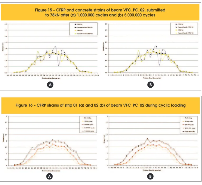
Figure [16 (a)] shows the strains in the CFRP strips, measured from the pre-loading up to 5.000.000 cycles. The most signii
-cant variations occurred up to 1.000.000 cycles. Strains in the CFRP strips varied about 0,85º/oo from the pre-loading up to
5.000.000 cycles.
The greatest differences regarding strains were found at 1,8m,
at 2,6m from the left side of the beam (Figure [16 (b)]).
Results indicate the existence of a kind of progressive strain at the anchorage regions, which can, eventually, generate adherence problems regarding long-term fatigue. Such effect should be better investigated, however, the long time demanded to realize fatigue tests, sometimes, inhibits this initiative.
Crack growing at mid-span of beam VFC_PC_01 can be observed at Figure [17], which shows the results of all crack opening mea
-surements made, from pre-loading up to 5.000.000 cycles. Figure [17] shows the results of crack openings and the respective posi
-tion from the left side of the beam, at mid-span, between the two central loading points (signaled on the igure by two vertical arrows. First cracks at mid-span appeared during pre-loading, reaching less than 0,15mm. From this point up to 100.000 cycle, crack open
-ings increased, but did not exceed 0,20mm. After 1.000.000 cycles the maximum crack opening was 0,22mm, and, after 5.000.000, this value was not exceeded.
Cracking at the gradual anchorage regions appeared just after 100.000 cycles, however, the maximum cracking opening ob
-served was 0,05mm. From 100.000 up to 5.000.000 cycles, the maximum crack opening measured at these regions was 0,10mm.. Results of crack openings obtained from beams VFC_PC_01 and VFC_PC_02 cannot be compared directly, due to the difference regarding the maximum and minimum loads applied to generate the cyclic loading.
As the maximum load applied on the beam VFC_PC_01 (108kN) was higher than the one applied on the beam VFC_PC_02 (78kN), beam VFC_PC_01 showed higher values of crack openings since pre-loading. Values of crack openings obtained after 5.000.000 cy
-cles, for beam VFC_PC_02, were reached by beam VFC_PC_01 after just 282.000 cycles.
5. Conclusions
Results of the reinforced concrete beams tested under cyclic load
-ing show that when these structures are post-strengthened with
Figure 13 – CFRP and concrete strains of beam
VFC_PC_02, submitted to 78kN, during pre-loading
Figure 14 – CFRP and concrete strains of beam VFC_PC_02, submitted
to 78kN after (a) 30.000 cycles and (b) 100.000 cycles
prestressed CFRP strips, damages that occur due to fatigue are mainly related to the level of stress at the steel rebars. Experimen
-tal results showed that the damage, which led to the rupture of the steel rebars, is related to the level of stress during loading, and, that it is not related to the type of post-strengthening.
Tests showed that an increasing of 20% in the maximum stress of the steel rebars signiicantly reduced the fatigue life time of the post-strengthened element, decreasing about 15 times the number of cycles up to failure. These results emphasize the importance of proceeding the monitoring of structures that are usually submitted to cyclic loading, such as highway and railway bridges. In some cases, when these structures were designed to support trafic loads smaller to the ones that they are submitted nowadays, the use of post-strengthening may increase their lifetime, since the use of post-strengthening may lead to a reduction in the stress level of the steel rebars.
6. Acknowledgements
Authors would like to acknowledge CNPq (Portuguese acronym of the Brazilian Ministry of Science’s National Research Coun
-cil) and CAPES (Portuguese acronym of the Brazilian Ministry of Education’s Higher Education Human Resources Development Agency) for providing the inancial support needed to develop this project. Authors would also like to express their appreciation for the technical support given by the research team at EMPA (Swiss Federal Laboratories for Materials Testing and Research), in Switzerland.
7. References
[01] MENEGHETTI, L. C. ; GARCEZ, M. R. ; SILVA FILHO, L. C. P. ; GASTAL, F. P. S. L. Fatigue life regression
Figure 15 – CFRP and concrete strains of beam VFC_PC_02, submitted
to 78kN after (a) 1.000.000 cycles and (b) 5.000.000 cycles
A
B
Figure 16 – CFRP strains of strip 01 (a) and 02 (b) of beam VFC_PC_02 during cyclic loading
Figure 17 – Cracking at mid-span
of beam VFC_PC_2 during test
FRP. Magazine of Concrete Research, volume 63,
2011. p. 539-549.
[02] MEIER, U. Strengthening of structures using carbon ibre/epoxy composites. Construction and Building Materials, volume 9, número 6, 1995. p. 341-351. [03] FERRIER, E.; BIGAUD, D.; HAMELIN, P.;