Fire design of reinforced concrete columns.
An alternative to the tabular method presented
by the Brazilian standard NBR 15200:2004
Dimensionamento de pilares de concreto armado em
situação de incêndio. Uma alternativa ao método tabular
da nbr 15200:2004
V. P. SilVA a [email protected]
a Professor Doctor, Departamento de Engenharia de Estruturas e Geotécnica da Escola Politécnica da Universidade de São Paulo – [email protected]
Av. Prof. Almeida Prado, trav2, n271, Edifício da Engenharia Civil – Cidade Universitária – 05508-900 São Paulo, Brasil
Abstract
Resumo
The Brazilian standard ABNT NBR 15200:2004 - Fire design of concrete structures gives a tabular method to the ire design of concrete columns, which associates the load level and the minimal dimensions of the cross-section and the place of the reinforcement centroid to the required time of ire resistance. This paper presents the theory of those tables and a study as a contribution to a future review of NBR 15200. A structural design more optimized, more correct and economic than the tabular method given by the Brazilian standard can be attained using alternative methods.
Keywords: ire, columns, concrete, standartization
A ABNT NBR 15200:2004 “Projeto de estruturas de concreto em situação de incêndio” apresenta um método tabular de dimensiona
-mento de pilares em situação de incêndio. O método associa o nível do carrega-mento e as dimensões mínimas da seção transversal e da posição da armadura na seção, ao tempo requerido de resistência ao fogo (TRRF). Neste trabalho, é apresentada a base teórica que permitiu a construção dessas tabelas e um estudo para contribuir com a futura revisão da NBR 15200. Um dimensionamento estrutural mais otimizado, mais preciso e econômico, se comparado ao método tabular da norma brasileira, pode ser obtido com o uso de métodos alternativos.
1. introduction
The scope of this work is contribute to Brazilian standardization and technical community, disclosing simpliied processes for the design of concrete columns in ire situations based on Eurocode 2 [1]. These methods can be used as more precise and economical alter
-natives to the tabular method presented by ABNT NBR 15200:2004 [2]. Based on European procedures, an expression and a simpliied table are derived and it is being proposed to insert them in a revision of NBR 15200. The Brazilian standard is recent and is still being evaluated and understood by the technical community. This work aims to bring an advance in relation to standard’s approach.
2. Brazilian standard ABNT
NBR 15200:2004’s approach
The ABNT NBR 15200:2004 [2] Brazilian standard ixes the design criteria for concrete structures in ire situations. In some states (Sao Paulo [3], Minas Gerais [4] and Goias [5], for instance), there is a speciic legislation to be followed and this standard is cited as a reference. The general purposes of verifying structures in ire situ
-ations are: lowering the risk to human lives; to limit neighborhood risks and to limit the risks of the property that is exposed to ire. As long as plastic effects, ruins and still local collapses are accept
-able, the structure can only be reused, after a ire, if it is inspected, have its remaining capacity checked and its recovering designed and executed. In normal conditions, structures are designed in room temperatures and, depending on its characteristics and use, may be veriied for ire situation. This veriication can only be done by ulti
-mate limit state, for the corresponding accidental combination. The action corresponding to ire can be represented by a time in
-terval of exposition to a standardized temperature rising known as standard-ire (ABNT NBR 5628:2001 [6], ISO 834 [7]). ABNT NBR 14432:2000 [8] deines this time interval called required time for ire resistance (RTFR) from the characteristics of the construction and its use. The heat transferred to the structure within this time interval (RTFR) generates in each structural element a certain tem
-perature distribution, which is a function of its shape and exposi
-tion to the ire. This process causes the decreasing of material’s strength, besides indirect action effects due to axial elongations or thermal gradients. ABNT NBR 15200:2004 [2] admits that efforts generated by heating can, in general, be neglected, since stiffness of the structural elements decreases and the capacity of plastic
adaptation increases with temperature.
So, the usual veriication of structure in ire situation is reduced by demonstrating the condition of eq. 1.
where:
Sd,i – designed value of effect of actions in ire situation Rd,i – designed value of the resistance in ire situation
γg,i, γq,i – partial factors for permanent and variable action in ire
ψ2j – factor for quasi-permanent value of a variable action j Fgk, Fqk – characteristic values of permanent e variable actions,
respectively
fck (θ), fyk (θ) – reduced characteristic values of concrete and steel
strength, respectively, at temperature θ.
For simplicity, NBR 15200 allows that the designed effect of actions in ire situations (Sd,i) is 70% of the designed effect of actions at room temperature (eq. 2), whichever the considered actions com
-bination. Eq. 2 neglects any action generated by imposed strains in ire situation.
For the veriication of eq. 1, NBR 15200 allows tabular methods,
simpliied or general design methods and tests.
In the case of columns, the tabular method explicit shown by NBR 15200 ixes minimum dimensions for columns in ire situation, ac
-cording to table 1. where:
bmín is column’s minimum dimension
c1mín is the minimum distance between the axis of the longitudinal
reinforcement and the nearest surface of concrete exposed to ire
NSd,i is the design value of the compression force in ire situation,
that should be of immediate application. Moreover, when the rela
-tion “μi” presented results that were different from that tabulated, the strenght should be determined by means of a double linear interpolation, among the geometrical values of the columns’ cross section that could provide the required resitance, for it was neces
-sary to determine the resistant ire moment resistanced.
The columns which reinforcement diameters were around 25 mm presented a performance that was quite smaller then the expected, when compared to the columns with diameters around 16 mm. The reduction of ire resistance was due to the incidence of spalling along the edges of the quite bigger section when the column con
-tained high diameter bars (Franssen [10]; Aldea et al. (1997), apud Costa [12]; Franssen (2001) apud Costa [13].
The tests also conirmed the inluence of the loading level, the slenderness and the cross section dimensions over the column’s ire resistance (Franssen [10]).
Based on experimental and numerical results, a new model of calculation was stablished taking into account the loading level, the mechanical ratio of reinforcement, the distance c1, the buck
-ling lenght, cross section dimensions and number of bars along the section. The column’s ire resistance time can be evaluated by means of eq. 3, which was included to Eurocode 2, in the versions later than 1995.
Where:
Ra = 1,60 (c1 - 30), c1 in mm
Rl = 9,60 (5 - ) Rb = 0,36 b’
Rn = 0 for n = 4, where n is the number of longitudinal bars Rn = 12 for n > 4
Where:
the mechanical ratio
NSd,i is the design value of the axial force in ire situation
NRd is the design value of the compression resistance at room tem
-perarure according to ABNT NBR 6118:2004 [14], with γm for room
temperature including the effects of geometrical non-linearities
(2nd order) and an initial eccentricity equal to the eccentricity of NSd,i. c1mín is the shortest distance between the centroid of the longitu
-dinal reinforcement and the nearest surface of concrete exposed to ire
ℓ0,i is the effective lenght (buckling) of the column in ire situation in meters
NRd is the design value of the compression force resistance, con
-sidering the eccentricities due to non-linearity (second order) in normal situation.
RTFR is the required time for ire resistance according to ABNT NBR 14432:2000 [8]
NBR 15200 was based in Eurocode 2 [1]
3. EUROCODE 2’s approach
NBR 15200 allows the use of more precise methods than that used in the construction of Table 1.
Eurocode 2 [1] presents two simpliied methods for concrete col
-umn ire design. The method A, developed by Prof. Jean-Marc Franssen of the University of Liege and the method B, developed by Eng. Jose Maria Izquierdo (Information obtained in a meeting with Eng. Izquierdo in 2006, in Madrid.).
The method A is analytic and allows to determine the time of ire resistance (TFR) in function of several parameters, being bmin and
c1 among them. By limiting the values of some intervenient param
-eters in method A, it is possible to build a table of minimum dimen
-sions. This table is presented in Eurocode 2 [1] and it is similar to Table 1, extracted from ABNT NBR 15200:2004 [2].
The method B is tabular and based on the same procedures for column design at room temperature, with the reductions of strenght due to high temperature.
Both methods consider, by hypothesis, that columns have ixed ends in ire situation. It may be remembered that, according to ABNT NBR 8681:2003 [9], wind effects can be overlooked in the presence of thermal action. Thus, these methods can be used in cases where displacements from non-linearities (second order) due to out-of-plumbness, even in normal structures with γz a little
higher than 1,1, are not relevant. The author suggests that, in any case, γz ≤ 1,3 at room temperature.
3.1 The method A
The method A supplied by Eurocode 2 [1] for the design of con
-crete columns in ire situation was based on the propositions of Franssen [10], presented in SiF 2000 - First International Work
-shop Structures in Fire, which took place in Copenhague, 2000. This method resulted from an integrated experimental program, involving numerical and physical experiments, performed by Liège and Gent (Belgium), Braunschweig (Germany) Universities and Ottawa Fire Research Station laboratory (Canada).
As a whole, 82 columns were tested, taking by reference the stan
-dard dimensions from the tabular method presented in the 1995 version of Eurocode 2 [9]. The numerical tests were performed with the help of SAFIR computer software.
The tests showed that the dimensions standardized by Eurocode 2 – 1995 [11] lead to unsafe results, because the diameter and number of bars of the reinforcement and the slenderness affect the column’s resistance in ire situation.
Besides, 1995’s tabular method was not of immediate use as it was supposed to be. It was necessary to calculate the relation
b’ = 2 Ac/(b+h)
Ac is the area of the column’s cross section, in square milimeters
b is the shortest dimension of the column’s cross section in mili
-meters
h is the longest dimension of the column’s cross section in mili
-meters
Eq. 3 is conditioned to the following limits: – As/Ac ≤ 0,04
– 25 mm ≤ c1 ≤ 80 mm
– 200 mm ≤ b’ ≤ 450 mm – h ≤ 1,5 b
– e ≤ 0,15 b (1st order eccentricity)
– ℓ0,i ≤ 6 m
Where
As is the total area of the reinforcement
“e” is the 1st order eccentricity of the compression force
3.1.1 On the determination of Rμ
From the general equation (4) and the particular equation (5), for αcc = 0,85, it is possible to derive eq. 6.
Admitting that αcc = 0,85 (deleterious effect of the long duration
loads, better known as Rüsch effect, concrete maturation and shape of the proof test body), eq. 6 is simpliied and Rμ can be
calculated as Rμ = 83 (1 – μi). It is pointed out that Table 1, ex
-tracted from NBR 15200, was constructed from Eurocode 2, which considered αcc = 1,0, hence in the next revision of the Brazilian
standard the tabulated values may be adapted to Brazilian reality, i.e., αcc = 0,85.
The NBR 15200 suggests that NSd,i can be evaluated by 0,70 x NSd.
By this way, µi would be equal to 0,70 x NSd/NRd. Considering, for
safety, NSd = NRd, one inds that µi = 0,7 and, inally, eq. 7.
3.1.2 On the determination of Ra
c1 is the shortest distance between the longitudinal reinforcement
axis and the concrete surface exposed to ire. When reinforcement bars are disposed in layers, c1 is the mean distance to the concrete
surface (c1m). The value of c1m must always be the smallest value
between the following:
Where c1xi and c1yi are the distances from bar i, with area Asi, to the
closest heated surface
In the example of igure 1, supposing ire at the four faces, we have:
If all bars diameters are equal, it results:
2
c
c
c
and
3
c
c
2
c
1x1 1x2 1ym 1y1 1y2 1xm+
=
+
3.1.3 On the determination of Rℓ
The effetive lenght of one column in ire situation ℓ0,i can be sup
-posed to be the effective lenght (buckling) at room temperature ℓ0
for all cases. For bracing structures of buildings which loors are compartmented, where RTFR is higher than 30 min, the effective lenght ℓ0 can be supposed to be 0,5 ℓ for intermediate loors and 0,7
ℓ for the top loor, where ℓ is the column’s actual lenght (center to center) as igure 2 (Eurocode 2 [1]).
Therefore, for the columns of multiple story buildings, where it is supposed that the compartment under ire is ixed to the upper and lower cold loors and that the highest loor column has a structural reserve that is greater then that of the other loors, it can be sup
-posed that ℓ0,i = ℓ/2 for all loors and, hence, in simpliied form, Rℓ can be calculated using eq. 8.
Where ℓ is the actual lenght of the column, in meters.
Despite the fact that the perfect two ends ixing of the columns in the cold loors have been objected by international research
-ers (Wang [15]; Gomes et al. [16]; Rodrigues et al. [17]), it was decided to keep this simpliication in this work having in mind that Eurocode, the basis of the main Brazilian structure standards, still keeps it.
3.1.4 On the determination of Rb
Rb may be rewritten as: 0,36 Ac/u, where u is the perimeter of col
-umn’s cross section in milimeters. Following the limitations of use for eq. 3, according to Eurocode 2 [1], the expression for the cal
-culation of Rb must obey, simultaneously, the limits of inequalities
9a and 9b:
Inequality 9a can be rewritten in the shape of inequality 10.
Inequality 9b can be rewritten in the shape of inequality 11.
Separating inequality 10, we have: - For 100 ≤ b ≤ 200,
100
100
−
≥
b
b
h
and225
225
−
≥
b
b
h
the last inequality is automaticallyirst inequality, which can be rewritten in the form: Rb ≥ 18 mm
– For 200 < b ≤ 225,
100
100
−
≥
b
b
h
and225
225
−
≥
b
b
h
the irst inequality is alwaysre-spected in view that, by deinition, h is higher than or equal to b and the second inequality is automatically respected since h must be positive.
– For 225 < b ≤ 375,
225
225
100
100
−
≤
≤
−
b
b
h
b
b
. This interval is always veriied, in view
that b ≤ h ≤ 1,5b.
– For b > 375,
225
225
100
100
−
≤
≤
−
b
b
h
b
b
the lowest limit is always veriied, in view
that h is, by deinition, higher than or equal to b. So, it is enough to verify the highest limit that can be rewritten in the form: Rb ≤ 40,5 mm.
This analysis can be performed graphically (ig. 3) in which the shaded area represents the limit hxb for the determination of Rb.
Therefore, a simple way to present the calculation of Rb, and its
limitations, would be in the form shown by ineq. 12.
For b ≥ 200 mm, the lowest limit of eq. 12 will be always respected. For h = b = 190 mm, an usual value in Brazil, the lowest limit will result 17,1 mm. The author believes that this small variation of the
lowest limit does not impair the method’s use.
3.2 The method B
From the direct method for design concrete columns, Izquierdo (see beginning of item no. 3) constructed tables 2 to 10, that are inserted in Eurocode 2 (2004). These tables indicate the minimum dimensions and distance (c1) from the bars’ axis to the nearest sur
-face for concrete columns of rectangular or circular sections with more than one face exposed to ire.
For columns where As ≥ 0,02 Ac, an uniform reinforcement distribu
-tion is necessary along the sec-tion sides for RTFR ≥ 90 min In table 2 and 10, the following simbology is used:
– reinforcement’s mechanical ratio
– column’s loading level at room temperature
– 1st order eccentricity at room temperature
As is the total area of reinforcement’ bars sections;
Ac is the area of concrete section;
fyd is the design value of steel’s strength at room temperature
is the design value of concrete’s strenght for -compression at room temperature
N0Sd is the design value of 1st order compression resistance at room
tempertaure
is the slenderness in ire situation
r = is the radius of gyration
4. Proposal of alternative design methods
to NBR 15200
4.1 Simpliied Analytic Method
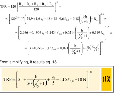
From eq. 3, supposing: μi = 0,7, αcc = 0,85 and that the lowest limit
of eq. 12 is acceptable for b = 190 mm, we have :
From simplifying, it results eq. 13.
Where:
TFR – column’s time of ire resistance, in min;
h – biggest column’s dimension, in mm. For h ≥ 1,5 b, use h = 1,5 b b – smallest column’s dimension, in mm
For
225
m
m
1
b
h
h
≥
+
use1
225
m
m
b
h
h
=
+
c1 – distance between the geometric center of the bars and the
nearest heated surface, in mm
ℓo,i – effective lenght (buckling) of the column in ire situation, in m
(see item 2.1.3)
N=0 if the number of longitudinal bars is 4
N=1/7 if the number of longitudinal bars is greater than 4 Eq. 13 is valid for:
– b ≥ 190 mm – ℓ0,i ≤ 6 m – µi ≤ 0,7
– As/Ac ≤ 0,04
– 25 mm ≤ c1 ≤ 80 mm
– e ≤ 0,15 b – αcc = 0,85
Figure 4 shows the results of a parametric analysis of time of ire resistance (TFR) as a function of b, L (actual), c1, μi and num
-ber of bars. The basic values for this analysis were: 30 cm, 4 m, 40 mm, 0,7 and 4 bars, respectively, h = 1,5 b and ℓ0,l = ℓ/2. This analysis also served for comparison of results by means of eq. 3 (Eurocode 2) and eq. 13, here suggested for standardization. As one can see, TFR varies sensibly with parameters variation. The results obtained by eq. 13 are slightly against safety if compared to Eurocode 2 [1], but, having in mind the method’s simplicity, it is perfectly acceptable.
4.2 Proposal for a new tabular method
Table 1 of ABNT NBR 15200:2004 was constructed from the meth
-od A, considering the extreme limits of dimensions, among them ℓ0,i ≤ 3 m, that, for intermediate columns of multiple story buildings,
table 1, respecting the ield of validity of eq. 3, specially the small eccentricity. For columns of high eccentricity, the use of the method B is recommended.
From the methods A and B it is feasible to create table 11, which immediate use is proposed for reinforced concrete design and that should be considered in a future revision of ABNT NBR 15200, for: – it leads to more economical results than the table 1 (extracted from ABNT NBR 15200:2004) for current cases
– it its in the advanced methods allowed by the Brazilian standard – it is applicable to the majority of current cases of columns for buildings
– it includes the validity limitations of table 1 that are not explicit in ABNT NBR 15200:2004
For the construction of “e ≤ 0,15 b” table’s column, the expression of the method A of Eurocode 2 was used, with the following as
-sumptions:
h = b
μi = 0,7
ℓ = 4 m ℓ0,i = ℓ / 2
αcc = 0,85
For the construction of “e ≤ 0,25 b” table’s column, the method B of Eurocode 2 was used.
The limitations indicated by table 11 must be respected. The other limitations cited in this work are automatically veriied if the tabu
The cases not covered by table 11 can be resolved by the direct utilization of both methods presented by this work.
5. Conclusion
This work presented the methods that are recommended by Euro
-code 2 [1] for ire columns design: the method A, analytic and the method B, tabular general.
These methods are applicable for bracing structures, although, ac
-cording to ABNT NBR 8681:2003 [9], the effect of wind can be disregarded in exceptional combination. So, these methods can be used in the cases of normal structures with γz slightly higher
than 1,1, when non-linear displacements (2nd order) due to
out-of-plumbness can be overlooked. It is suggested, however, that, in any case, γz ≤ 1,3 at room temperature.
One of these methods (A) was used as a basis for the tabular method presented by ABNT NBR 15200:2004 [2]. Nevertheless, some restrictions for its use were omitted and, on the other hand, with the transformation of the analytic method in tables, some limit situations were considered, which lead to anti-economical values for o high number of current situations. Here, a simpliied analytic expression is proposed for standardization purposes.
From both methods, an alternative table is also proposed to that of ABNT NBR 15200:2004 [2], valid for more common situations than that admit
-ted (without being explicit) by the Brazilian standard. This table leads to more precise and economical values when compared to the standard.
6. References
[01] EUROPEAN COMMITTEE FOR STANDARDIZATION (CEN). Eurocode 2: Design of concrete structures –
Note: According to ABNT NBR 8681:2004 [9], the effect of wind can overlooked for accidental combination. This table can be used in the case
of normal structures with γz slightly higher than 1,1, where non-linear (2
nd order) displacements due to out-of-plumbness can be overlooked. The
author suggests that, in any case, γz ≤ 1,3 at room temperature.
Part 1.2: General Rules – Structural Fire Design. EN 1992-1-2. Brussels. 2004.
[02] ASSOCIAÇÃO BRASILEIRA DE NORMAS TÉCNICAS (ABNT). Projeto de estruturas de concreto em situação de incêndio (Fire design of concrete structures). NBR 15200. Rio de Janeiro. 2004. [03] CORPO DE BOMBEIROS – POLÍCIA MILITAR
DO ESTADO DE SÃO PAULO (CB-PMESP). Segurança estrutural nas ediicações – Resistência ao fogo dos elementos de construção (Fire Safety of Buildings - Fire resistance of constructive elements). Instrução Técnica do Corpo de Bombeiros (Technical Instructions of Fire Department). IT 08:04.
Sao Paulo. 2004.
[04] CORPO DE BOMBEIROS MILITAR DO ESTADO DE MINAS GERAIS. Segurança estrutural nas ediicações (Fire safety of buildings). Instrução Técnica. IT 06:05. Belo Horizonte. 2005.
[05] CORPO DE BOMBEIROS MILITAR DO ESTADO DE GOIÁS. Segurança estrutural nas Ediicações – Resistência ao Fogo dos Elementos de Construção (Fire Safety of Buildings- Fire resistance of constructive elements). Norma Técnica 08. Goiania. 2007
[06] ASSOCIAÇÃO BRASILEIRA DE NORMAS TÉCNICAS (ABNT). Componentes construtivos estruturais - Determinação da resistência ao fogo (Fire resistance determination). NBR 5628. Rio de Janeiro. 2001.
Tests – Elements of Building Construction – Part 1.1: General Requirements for Fire Resistance Testing. ISO 834. Geneva. 1990. [Revision of irst edition (ISO 834:1975)]
[08] ASSOCIAÇÃO BRASILEIRA DE NORMAS TÉCNICAS (ABNT). Exigências de resistência ao fogo de elementos construtivos das ediicações (Fire-resistance requirements for building construction elements). NBR 14432. Rio de Janeiro. 2000. [09] ASSOCIAÇÃO BRASILEIRA DE NORMAS
TÉCNICAS (ABNT). Ações e segurança nas estruturas (Actions and safety of the structures). NBR 8681. Rio de Janeiro. 2003.
[10] FRANSSEN, J.-M. Design of concrete columns based on EC2 tabulated data – a critical review. In: Structures in ire – proceedings of the irst international workshop. 2nd edition. Copenhagen: University of Liege/Danish Institute of Fire Technology/CIB-W14 Fire, 2000.
[11] EUROPEAN COMMITTEE FOR STANDARDIZATION (CEN). Eurocode 2: Design of concrete structures – Part 1.2: General Rules – Structural Fire Design. prEN 1992-1-2. Brussels. 1995.
[12] COSTA, C. N. Estruturas de concreto em situação de incêndio (Concrete structures in ire). Dissertation for master degree in Civil Engineering – Structures. Escola Politécnica da Universidade de São Paulo. Sao Paulo, 2003
[13] COSTA, C. N. Trial of the tabular “A”method of the Eurocode 2-1-2:2004 for the ire of reinforced columns. Final Report. MACE-UMIST. Manchester. 2006
[14] ASSOCIAÇÃO BRASILEIRA DE NORMAS TÉCNICAS (ABNT). Projeto de estruturas de concreto (Design of concrete structures). NBR 6118. Rio de Janeiro. 2004.
[15] WANG, Y. C. Steel and Composite Structures. Behaviour and Design for Fire Safety. Spon press. London. 2002.