Volume 7, Number 1 (February 2014) p. 138-157 • ISSN 1983-4195
The bond between steel and concrete is essential for the existence of reinforced concrete structures, as both materials act together to absorb structural strain. The bond phenomenon is considered to be complex regarding many factors that affect it. Several types of bond tests have been proposed over years. One is the modiied proposed of pull-out test, which was elaborated by Lorrain and Barbosa [1] called APULOT test (Ap -propriete pull-out-test). Based on experimental results obtained by Vale Silva[2] either by conventional pull-out tests, or by modiied pull-out test, APULOT, seeks to know the numeric behavior of bond steel-concrete through a numerical simulation using a calculation code ATENA which is based on the Finite Element Method (FEM). The numerical simulation provided better evaluate the stress distribution and cracking that occurs during the test, thereby becoming a valuable tool to support the experimental project that aims to validation, validation partially or not recommend the modiied bond test steel-concrete - APULOT test – as quality control test of structural concrete. The numerical results showed good represen -tation compared to experimental results.
Keywords: bond steel-concrete, numerical analysis, pull-out, APULOT, pull-out test.
A aderência entre o aço e o concreto é fundamental para a existência das estruturas de concreto armado, uma vez que os dois materiais atuam em conjunto para absorver os esforços solicitantes. O fenômeno da aderência é considerado complexo no que se refere aos vários fatores que o inluenciam. Vários tipos de ensaios de aderência foram propostos ao longo dos anos. Um deles é a proposta modiicada do ensaio de ar-rancamento pull-out-test, que foi elaborada por Lorrain e Barbosa [1] denominado de ensaio APULOT (Appropriete Pull-Out-Test). Com base nos resultados experimentais obtidos por Vale Silva [2] para os ensaios pull-out convencionais e para o ensaio pull-out modiicado, APULOT, procura-se conhecer o comportamento numérico da aderência aço-concreto através de uma simulação numérica utilizando um código de cálculo chamado ATENA que é baseado no Método dos Elementos Finitos (MEF). A simulação numérica permitiu melhor avaliar a issuração e a distribuição de tensões que ocorre durante o ensaio de arrancamento, tornando-se com isso, uma ferramenta de apoio preciosa ao pro -jeto experimental que visa à validação, validação parcial, ou não recomendação do ensaio de aderência aço-concreto modiicado – Ensaio APULOT – como ensaio de controle de qualidade do concreto armado. Os resultados numéricos obtidos apresentaram boa representatividade quando comparados aos resultados experimentais.
Palavras-chave: aderência aço-concreto, análise numérica, pull-out, APULOT, ensaio de arrancamento.
Bond steel-concrete: simulation analysis of the pull-out
tests and APULOT using the program ATENA
Aderência aço-concreto: simulação numérica
dosensaios de arranchamento pull-out e APULOT
usando o programa ATENA
A. J. TAvArEs a [email protected]
M. P. BArBOsA a [email protected]
T. N. BiTTENcOUrT b [email protected]
M. LOrrAiN c [email protected]
a Departamento de Engenharia Civil, Universidade Estadual Paulista, Ilha Solteira, SP, Brasil;
b Departamento de Estruturas e Geotécnica, Escola Politécnica da Universidade de São Paulo, SP, Brasil; c INSA-Toulouse, Departament de GenieCivi,, Toulouse, France.
Abstract
1. introduction
The steel-concrete bond has been investigated for a long time in many countries. These studies are closely linked with the evolu -tion of reinforced concrete. The irst scientiic articles on the steel-concrete bond date back to the early twentieth century [Carl Von Bach (1905), Bach (1905), Koenen (1905), Kollbohm and Mautner (1907)], and today it’s the subject of such scientiic meetings as BIC2012 (Bond in Concrete 2012, Bresquia - Italy) supported by the ACI, RILEM and FIB. This interest is justiied by its importance in reinforced concrete and prestressed concrete parts. In order to understand these part so that their behavior and the anchoring of the reinforcement is ensured, and, consequently, to ensure their safety, the bond phenomenon must be understood in detail. One of the most popular and traditional bond tests is the direct pull-out test, called the pull-pull-out test, normalized by RILEM / CEB / FIP RC6 [3] and ASTM [4]. It is a test of reinforced concrete composite materials to seeks to assess the strength of the bond between the concrete and the reinforcement.
Based on previous studies, Lorrain and Barbosa [1] and Lorrain et al. [5] presented a simpliied alternative to the pull-out test, called the APULOT test, to be used in situ. The procedures of this new test are being studied, discussed and improved by some research groups located in Brazil, France, Spain, Tunisia and Paraguay. The validation of this new test could provide an alternative for the eval-uation of reinforced concrete quality in civil constructions.
Vale Silva [2] investigated the proposal by Lorrain and Barbosa [1] of comparing two types of steel-concrete bond tests: the pull-out test and the APULOT test. The results showed on the pull-pull-out tests that the type of rupture was observed the sliding for all diam-eters. However the results obtained for the APULOT test showed different behavior for bars with diameters of 8.0 mm, 10.0 mm and 12.5 mm. Vale Silva [2] believes that this behavior variation is re-lated to the diameter of the specimen prepared with molds as PET bottles (Polyethylene Terephthalate), which did not have suitable dimensions suitable for withstanding the stresses induced with the enlargement of the diameter of the reinforcing steel bars, or the inadequate anchorage length used. This study evaluates the distri
-numerical analysis
The numerical simulation of the pull-out and APULOT tests is a tool to support an experimental project aimed at the overall vali-dation, partial valivali-dation, or to establish the undesirability of the APULOT test for reinforced concrete quality control testing. These simulations, when compared with the experimental results, assist in the choice of some parameters that affect the behavior of the steel-concrete bond, such as the strength of the concrete, the di-ameter of the reinforcement and the variation in the anchorage length, among others.
2. steel – concrete bond
The steel-concrete bond is one of the most important mechanisms in reinforced concrete structures, since both materials must act jointly to absorb internal forces. This bond is responsible for an-choring the reinforcement in the concrete and also serves to pre-vent slippage of the bar segments between cracks, thus limiting the opening of the cracks.
According to Tassios [6] and Ducati [7], the behavior on the limit between the bar and the concrete is of decisive importance for the load capacity and service of reinforced concrete parts. This knowledge is essential in order to reach the anchorages calcula-tion rules and splices by transpassive of reinforcement bars, for the delections calculation considering the effect of stiffening traction, for crack control and therefore the minimum amount of reinforce -ment. This can be extended to the durability of the structures. According to Tassios [6] the eficiency of the steel-concrete con -nection can be quantiied by the bond stress versus sliding ratio, which expresses the strain that arises in the concrete steel inter-face related to the relative displacement between the steel bar and the concrete that surrounds it. A little sliding suggests local dam-age or the interface accommodations. When these two actions oc-curred together, i.e., when the slide reaches the maximum value, indicate the destruction of the bond, which can be associated with a certain state of deformation and cracking. Some limits values of sliding and procedures of structural design were presented in
Bond steel-concrete: simulation analysis of the pull-out tests and APULOT using the program ATENA
the standards, which are usually associated with an unacceptable state of deformation and cracking (Caetano [8]).
The sliding at the beginning of loading is caused in part by the elastic deformation of the concrete. For higher loads, however, it is caused by crushing of the concrete on the bar ribs. In Bars with-out ribs the bond occurs because of the chemical bond between the cement paste and the bar. When the chemical bond is broken, there occurs a resistance to sliding due to friction. When this resis-tance is reached, the splitting is not complete, but the bar is pulled out, resulting in an almost intact hole inside the concrete (Goto [9]). In ribbed bars, which were developed to produce a stronger bond than in bars without ribs, the bonding phenomenon occurs in a dif-ferent way. Although these bars are developed adhesion and fric-tion, the resistance to sliding in ribbed bars depends mainly on the mechanical action between the concrete and the ribs. The effect of chemical adhesion is small and no friction occurs until there is slid-ing between the bar and the concrete (Vale Silva [2]).
2.1 Bond tests
Among the various types of testing proposed (eccentric pull-out test; beam test; pull-out test with circumferential ring - ring test - out test , among others), which determine the bond stress values between the steel reinforcement and the concrete, the so-called pull-out test should be highlighted. This test consists of pulling a steel bar positioned in the center of a concrete prism. The two ends of the steel bar out of the concrete prism where the load is applied to one end and read the sliding at the other end.
In pull-out test occurs a longitudinal compression component, and to minimize this effect, a non- bonded zone after the backing plate is considered. This component does not exist in anchorage areas of tensile reinforcement of beams subjected to bending (Fusco [1]). Figure 1 shows the direct pull-out test, with the trajectories of ten-sile and compression stresses.
Once the steel-concrete connection is broken, the bar moves with more intensity inside of the concrete prism depending on the sur-face roughness involved (slick bar or ribbed bar). The maximum value of resistance allows us to calculate the connection ultimate stress (maximum) (τu) obtained by dividing the maximum force
ap-plied by the nominal anchoring surface.
2.2 APULOT test (modiied Pull-out test)
Lorrain and Barbosa [1] and Lorrain et al. [5] proposed a modiica-tion of the pull-out test, which was named the APULOT test. This test uses cylindrical plastic bottles (PET) discarded in nature as a template, with a minimum diameter of 8 cm and, if possible, with a more homogeneous form in the bonded zone. Figure 2 shows the “APULOT” test with the bonded zone location and the traction and compression trajectories. A change made in this test is the fact that the specimen remains inside the plastic bottle (PET), which results in reduced lateral deformation. In the APULOT test, the anchorage length (bonded zone) will depend on the concrete compressive strength (fcm) and the diameter of the steel bar (
φ
), based on the concept of balancing the stresses necessary to anchor a steel bar in concrete, according to Equation 1.(1)
L=
4
f
y
·
·Ø
τ
u
where: = anchor length (mm); fy = steel yield strength (MPa);
φ
= bar diameter (mm);τ
= last Bond Strength (MPa);Figure 2 – Schematic of APULOT test (Vale Silva [2])
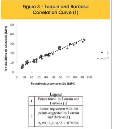
obtained by the correlation curve adopted by Lorrain and Barbosa [1] (Figure 3).
In determining the anchorage length using Equation 1 adopts the mate-rials resistance values used as the age provided of the tests. Vale Silva [2] used the value of L = 10
φ
in his experimental tests as the average of concrete compressive strength (fcm) of 27,8 MPa at 28 days and 6φ
as the average of concrete compressive strength (fcm) 49,3 MPa at 28 days. These data are used for the numerical analysis of this test.3. Numerical analysis
3.1 Calculation Code: ATENA
The calculation code ATHENA (Advanced Tool for Engineering Non -linear Analysis) has been used in structural engineering to simulate the behavior of concrete and reinforced concrete structures, as well as of concrete cracking. It uses the inite element method for the nonlinear analysis of structures, simulating the real behavior of structures either through linear or nonlinear analyses. The total ac-tion active was deined by the time integral of forces increments, with application of the Newton-Rhapson or Arc-Length Methods.
The materials were characterized through their properties and physical parameters and into groups according to their constituent features.
Among the properties of steel, are its stress-strain ratio in the elas-tic-linear or multilinear mode, with or without a deined low level; the nonlinear model of loading and unloading cycles, and the crite-rion of von Mises low.
Among the concrete properties are: the stress-strain law and the ruin plan of the structure, determined by criteria of Drucker-Prager plasticity (compression) and Rankine failure (traction). The soft-ware allows two models of the above described combination to simulate the breaking and cracking of concrete.
The constitutive models of each material were described in Cer-venka [12].
In this paper, the Newton-Rhapson analysis method was used with increments of displacements of 0,06 mm in each step.
The Newton-Rhapson method adopts the concept of strength increments that were performed iterative calculations each step loading until there is a convergence between the differential func-tion variables. The force was kept constant and the displacement was redeined until the tangent line of the force increment ind the force versus delection curve for each new iteration of a load step.
3.2 Interface constitutive model
The interface material model in ATENA can be used to simulate contact between two materials. The interface material is based on the Mohr-Coulomb criterion with the shear stress. The constitutive relation for a three-dimensional general case was given in terms of traction forces in the interface planes and relative displacements of running and opening (Equation 2).
(2)
{
τ
1{
τ
2σ
}
=
[
}
K
tt0 0
0 K
tt0
0 0 K
nn]
Δ
v
1Δ
v
2Δ
u
note the normal initial elastic stiffness and the normal initial elastic shear, respectively, and the shear relative displacement is repre-sented by Δv and the normal displacement is reprerepre-sented by Δu. The initial fracture surface corresponds to the Mohr-Coulomb con -dition (Equation 3) for a ellipsoid system under stress. Following stress violating this condition, the surface collapses into a residual surface corresponding to dry friction.
(3)
The failure criterion is replaced by an ellipsoid, which intersects the axis of the normal stress value of ft with the vertical tangent and the shear axis was trapped in the amount of c (cohesion) with the equivalent tangent -∅.
The limits of the stress were deined as “rupture areas” in Mohr space. Cox [13] deines those surfaces with only one function while Lundgren [14] applies two functions: F1 and F2.
According to Lundgren [14], it can be consider the problem as be -ing controlled by friction approximately, although the bond process in ribbed bars was made by mechanical engagement. The F1 func-tion describes the combinafunc-tions of stress that deine the start of slipping by friction, including the adherence fa. This function (Equa -tion 4) was deined by:
(4)
0
)
.(
1
=
t
t+
t
n-
f
a=
F
f
Where: ∅ is a friction apparent coeficient, tn is the normal stress, tt is the bond stress and fa adhesion. This surface was associated with the failure by cracking usually.
Bond steel-concrete: simulation analysis of the pull-out tests and APULOT using the program ATENA
The other function, F2, describes the failure limit by pullout. This func-tion is determined by the balance of forces resulting from the mechan-ical interaction between the steel-concrete, resulting in Equation 5:
(5)
F
2=t
t2+(t
n+fc)·(t
n-f
a)=0
Where: fc is the concrete compressive strength.
Figure 4 shows the rupture surfaces, which was deined by the F1 and F2 functions.
The friction coeficient (
φ
) is deined by Lundgren [14], as shown in Figure 5.The rupture surface decreases with the deformation process, since this parameter also decreases. This corresponds with a “softening” of the constitutive ratio with the dissipative processes.
Figure 5 – Friction coefficient variation as
a sliding function (based on Lundgren [14])
4. Numerical simulation
This paper conducted a numerical study of the pull-out and APU -LOT tests, comparing their behiavior with the experimentally re-sults obtained by Vale Silva [2].
4.1 Pull-out test
An analysis was performed with the experimental data obtained by Valley Silva [2] to the concrete compressive strength of 27,8
Figure 6 – Analyzed part demonstration
for the bar with 8 mm diameter
oduced by
MPa (Concrete T1) and 49,3 MPa (concrete T2) at 28 days with the steel bars with 8.0 mm , 10.0 mm and 12.5 mm diameters and yield stress (fy) equal to 625,0 MPa.
In order to reduce the number of elements, and consequently, the processing time, we used the “axial symmetry” analysis of the AT -ENA software considering the axisymmetric model, with the axial symmetry axis in the center of the concrete prism. Figure 6 shows
Figure 8 – Distribution of stresses and cracking. Concrete
of 27,8 MPa - 8.0 mm, 10.0 mm and 12.5 mm bars. Pull-out test
in detail the numerical scheme used in this case.
After analyzing the inite elements grids possible, we chose to use a grid with 943 elements and 1097 nodes.
The analysis of the grid and the parameters of the materials are shown in Tavares [15].
Figure 7 shows the force x sliding diagram comparing the experi-mental results with the numbers for the bars of 8.0 mm, 10.0 mm,
Figure 9 – Comparison of numerical results with experimental range from
Bond steel-concrete: simulation analysis of the pull-out tests and APULOT using the program ATENA
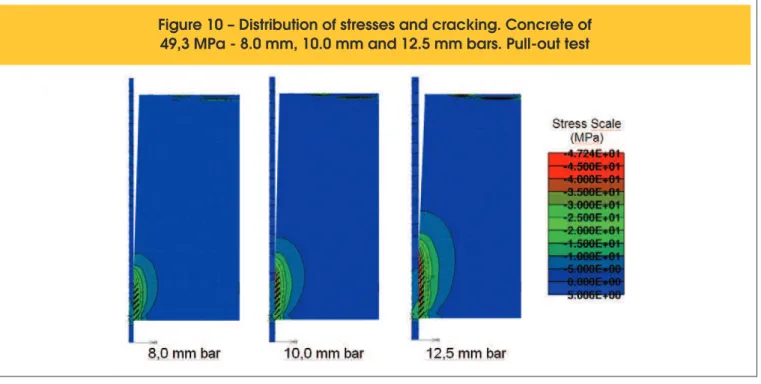
Figure 10 – Distribution of stresses and cracking. Concrete of
49,3 MPa - 8.0 mm, 10.0 mm and 12.5 mm bars. Pull-out test
12.5 mm and the concrete compressive strength of 27,8 MPa. Figure 7 reveals that the numerical results curves approach the range of experimental results. Figure 8 shows the distribution of stresses, cracking and the deformed structure for the 8.0 mm, 10.0 mm and 12.5 mm bars.
There is also an increase in the stress value and the cracking amount too, as well as the bar diameter increases from 8,0 mm to 12,5 mm, and the increase in the anchorage length. This can be explained by the fact that the stresses generated were supported by the concrete prism - with a larger contact area - there is a greater sliding
resis-Figure 11
– Comparison of numerical range with the experimental results by Vale Silva [2]
results –concrete with 27,8 MPa and 8,0 mm , 10,0 mm and 12,5 mm bars. APULOT Test
tance and increasing the stress and cracking at peak load.
The pull-out tests results for the concrete compressive strength at 28 days of 49,3 MPa (Figure 9) shown in the force-sliding diagrams compares the range of experimental results with the numerical re-sults for 8, 0 mm, 10.0 mm and 12.5 mm bars.
Figure 10 shows the stress distribution in the model with values presented in MPa in the description, together with the cracking and the deformed structure in the load step when it is reached the bond last stress value for the pull-out tests with concrete compressive strength equal to 49,3 MPa and 8,0 mm, 10,0 mm and 12,5 mm bars diameter.
In Figure 10 the same effect can be observed for the concrete called T1 (fc28 = 27,8 MPa), with an increase in the stress value and the number of cracks as the bar diameter increases and, con-sequently, an increase of anchorage length. Comparing Figures
Figure 12 – Stresses and cracking distribution. Concrete
of 27,8 MPa – 8,0 mm, 10,0 mm and 12,5 mm bars. APULOT Test
8 and 10, we observed that with the increase of the compressive strength of the concrete there was an increase of cracking and a higher stress value of the concrete.
4.2 APULOT Test
In the APULOT tests simulations, the asymmetrical analysis with the same type of inite element and the same constituent models for the materials of pull-out test were also used.
Figure 11 shows the APULOT force-sliding diagrams for test with
Bond steel-concrete: simulation analysis of the pull-out tests and APULOT using the program ATENA
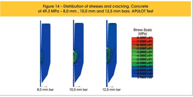
Figure 14 – Distribution of stresses and cracking. Concrete
of 49,3 MPa – 8,0 mm , 10,0 mm and 12,5 mm bars. APULOT Test
8,0 mm, 10,0 mm and 12,5 mm bars and the concrete compressivestrength of 27,8 MPa.
In the simulation with the steel bar of 8,0 mm, the curve of the numerical result fell within the range of experimental results range – including the after-peak representation – showing the bar slide in comparing to concrete. However, the numerical results with the bars of 10,0 mm and 12,5 mm represent the typical behavior of a rupture by splitting, although they have reached values until higher than the experimental results for the maximum stress in the after-peak region, as well as this behavior was also obtained in most experimental results – Vale Silva [2] in this case. Thus, the con -stitutive model used to represent the concrete and the interface is capable of simulating different modes of bond failure, i.e., the constitutive model can capture pullout and splitting mechanisms. The stress and cracking distribution in the concrete in the load step that which was reached the bond stress is given in Figure 12. Figure 12 reveals there was an increase in the stress value and also in the amount of cracks as the bar diameter increases from 8,0 mm to 12,5 mm, similar to the pull-out test.
Figure 13 shows the force-sliding diagrams comparing the numeri-cal result with the experimental results range related to the 8,0 mm, 10,0 mm and 12,5 mm bars with a concrete compressive strength of 49,3 MPa.
The bond failure mode was similar to the results obtained for the concrete of 27,8 MPa looking for these particular examples relat -ing to 49,3 MPa, i.e., there was ruptured by slid-ing for the 8,0 mm bar and a rupture by splitting in the 10,0 mm and 12,5 mm bars, which also occurred in the experimental results of Vale Silva [2] for the APULOT test with these bars. The maximum bond strength value of the numerical result reached the maximum level within the experimental results range for the three different diameters bars. Figure 14 shows the distribution of stresses and cracks in the load step which was reached to the bond inal stress.
According to Figure 14, the same effect occurs to the concrete
with 27,8 MPa (Figure 12): there was sliding of the 8,0 mm bar and splitting of the 10,0 mm and 12,5 mm bars.
5. conclusions
By analyzing the force-sliding diagrams, we concluded that the nu-merical results have an equivalent behavior to the results of experi -mental tests, validating the use of this model. In the pull-out tests and APULOT tests, we observed that an increase in bar diameter resulted in the increase of stresses in the concrete at the region of the bonded zone, for concrete with the same mechanical strength. However, when bar samples with the same diameter and with dif-ferent concrete strength were compared, there was an increase in concrete stress with increasing concrete compressive strength. In all pull-out tests the bond rupture occurred by sliding. In the APU -LOT tests, however, the bond rupture for the test with 8,0 mm bar occurred by sliding, whereas the bond failure mode occurred by splitting for the concrete mechanical strength used in the tests with 10,0 mm and 12,5 mm bars. This may be occurring because the concrete coverage around the bar is higher in the pull-out test than in the APULOT tests, thus contributing to a better distribution of the stresses generated during the test.
6. Bibliography
[01] LORRAIN, M; BARBOSA P. M. Controle de qualidade dos concretos estruturais: ensaio de aderência aço-concreto.
Revista Concreto & Construções, São Paulo, v.36, n.51,
2008, p.52-57.
[02] VALE SILVA, B. Investigação do potencial dos ensaios APU-LOT e pull-out para estimativa da resistência a compressão do concreto. 178f. 2010. Dissertação (mestrado em
RILEM/CEB/FIP RC6: bond test for reinforcing steel - 1 - pull-out test. Paris, 1983, 3p.
[04] AMERICAN SOCIETY FOR TESTING AND MATERIALS. ASTM. ASTM C234: standard test method for comparing concretes on the basis of the bond developed with reinforced steel. Philadelphia. 1991, 5p.
[05] LORRAIN, M; BARBOSA P. M. SILVA FILHO, L.C.P. Estima-tion of compressive strength based on Pull-Out bond test re -sults for on-site concrete quality control. REVISTA IBRACON DE ESTRUTURAS E MATERIAIS - RIEM, v. 4, p. 582-591.
2011.
[06] TASSIOS, T. Properties of Bond Between Concrete and Steel under Load Cycles Idealizing Seismic Actions. CEB, Bulletin d’Information, Roma, v.1, n. 131, 1979,p. 67-122. [07] DUCATTI, V. A. Concreto de elevado desempenho: estudo
da aderência com a armadura. 1993. 259f. Tese (Doutorado em Engenharia) - Escola Politécnica, Universidade de São Paulo, São Paulo.1993.
[08] CAETANO, L. F. Estudo do comportamento da aderência de elementos de concreto armado em condições extremas.
2008. 178f. Dissertação (Mestrado em Engenharia Civil). Programa de Pós-Graduação em Engenharia Civil, Univer -sidade Federal do Rio Grande do Sul, Porto Alegre. 2008. [09] GOTO, Y. Cracks formed in concrete around deformed ten
-sion bars. ACI Journal Proceedings, Michigan, v. 68, n.4,
1971, p. 244-251.
[10] FUSCO, P. B. Técnica de armar as estruturas de concreto.
São Paulo: PINI, 1995, 265p.
[11] LEONHARDT, F; MOMMIG, E. Construções de concreto.
Rio de Janeiro: Interciência.1979.
[12] CERVENKA, V.; JENDELE, L.; CERVENKA, J. ATENA Pro-gramDocumentation. Prague: Cervenka Consulting. Part 1. 2011.
[13] COX, J. V. Development of a Plasticity Bond Model for Re-inforced Concrete –Theory and Validation for Monotonic Ap-plications. Technical Report TR-2036-SHR. Naval Facilities Engineering Service Centre, Port Hueneme, USA. 1994. [14] LUNDGREN, K.; GUSTAVSON, R.; MAGNUSSON, J. Finite
element modelling as a tool to understand the bond mecha-nisms. In: BOND IN CONCRETE – FROM RESEARCH TO STANDARDS, Proceedings… Budapest. 2002.
[15] TAVARES, A. J. Aderência aço-concreto: análise numérica dos ensaios pull-out e APULOT.Dissertação (mestrado em
![Figure 1 – Details of the direct pull-out test. P. (Leonhardt and Mönnig [11])](https://thumb-eu.123doks.com/thumbv2/123dok_br/18860679.417873/2.892.59.840.822.1129/figure-details-direct-pull-test-p-leonhardt-mönnig.webp)
![Figure 4 – Flow surfaces (based on Lundgren [14])](https://thumb-eu.123doks.com/thumbv2/123dok_br/18860679.417873/4.892.454.832.306.437/figure-flow-surfaces-based-on-lundgren.webp)